OpenSprinkler Simple Web-based Control Program

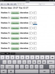
At times you may want a simple web-based interface to directly control each sprinkler valve, without having to set up a complex schedule. I’ve written the svc_simple_web program exactly for this purpose. To start, take a look at the web interface of this program:
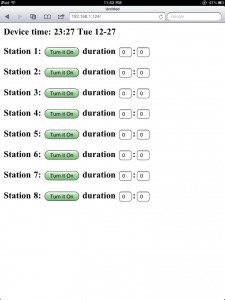
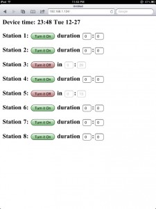
Quite simple, isn’t it. The top line shows the current time; underneath it is the list of eight sprinkler stations. Clicking a button will turn on the corresponding station, and clicking the same button again will turn it off. To make it a bit more useful, you can set a timer (i.e. duration) for each station. The duration is specified by the number of hours following by minutes (hh:mm). Once a station is turned on, the program will keep track of the running time and stop that station when the duration time is reached. Meanwhile, the webpage will display the remaining watering time. You can set an individual time for each station, say 30 minutes for station 3, and 15 minutes for station 5. Setting the duration to 0:0 means there is no time limit: once on, the station will only be turned off when you manually click on ‘Turn it Off’. This way, you can either manually control the stations, or set a timer for it.

If you are interested, feel free to try this program and let me know your comments. The program can be downloaded on the following page:

OpenSprinkler Download Page

Note that the software is now released in GitHub for the purpose of better version control. The code will be regularly updated. You can sign up for the RSS feed on the GitHub update history page, in order to track the updates.
OpenSprinkler ‘Weather’ Feature coming soon

This is a heads-up for the upcoming ‘weather’ feature in the OpenSprinkler software. It makes use of the Google Weather API to obtain current weather data in your local area. The Google Weather API returns data in XML format. Unfortunately the OpenSprinkler, which uses a small microcontroller, cannot directly handle the returned data. So what I had to do is to write a Python script that translates the XML data into something that’s much shorter and simpler, so that it can be processed by OpenSprinkler. I’ve put up the script on this website. You can try it by using the following url:

http://rayshobby.net/scripts/getweather.py?location=nyc

It returns a simple html page that’s well within a single Ethernet packet. One nice feature about using the Google API is that you can specify the location in a variety of different formats, such as zip code, city name, or sometimes abbreviated names like ‘nyc’. Feel free to give it a try. This script will be published later, so you can install it on any server you want.

Another feature is the weather forecasts. Right now I have no plan to use this information, but it may be useful for the future. You can get forecast data using:

http://rayshobby.net/scripts/getweather.py?location=nyc&forecast=1

It can return up to four days of forecasts.

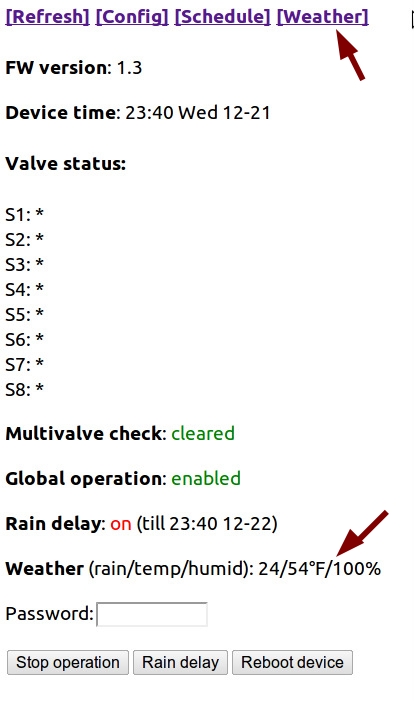
I’ve modified the Arduino code to periodically retrieve weather data from the server. The new OpenSprinkler webpage has the following changes:

Note the new ‘Weather’ link in the menu bar, and the weather information on the bottom, showing the current rain index, temperature, and humidity. The rain index indicates the heaviness of the rain, and translates to the rain delay duration. The program currently calculates the rain index from the weather description returned by the script. For example, ‘Rain’ or ‘Thunderstorm’ translates to a high rain index, while ‘Light Rain’ translates to a low rain index. In any case, this can be adjusted in software.
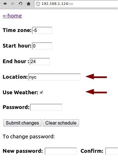
The configuration page has two added fields: the location, and the ‘Use Weather’ checkbox. Again, there is a variety of ways you can specify the ‘location’.

What I am currently working on is to update the software code to allow the control by weather data. The simplest way is to use the ‘rain index’ to control rain delay hours. More complicated strategy can be implemented by yourself. That’s the value of open-source and programmable gadgets!

Learn to Make Solder Paste Stencils

I’ve had some rudimentary experience with surface mount (SMT) soldering in the past. The method I learned basically involves squeezing out solder paste from a syringe onto the PCB, placing the components, and then using a hot skillet to reflow. It’s pretty easy to learn. But if I want to produce assembled PCBs in large quantity, the syringe method is not going to work well. Instead, I need to use a solder paste stencil to quickly apply solder paste onto PCBs.

Solder paste stencils (aka SMT stencils) are expensive if you want to order them. Even a small piece would cost $30-$40, and that’s often the price for just one. I wanted to learn how to make stencils myself, so I can produce them quickly, and as many as I want. I don’t own a laser cutter. Fortunately, I found this really clever method from Instructables. After trying it a couple times, I’ve got a good grip of it. Below I document the process with pictures. The method is essentially based on the Instructables article above, but combined with my own experience and tips.

Preparation

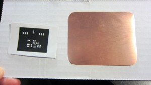
To begin, you need thin copper sheet. The thickness of the copper sheet should be around 3 to 4mil (0.003 to 0.004 inch). I got mine from Amazon: 12 inch by 12 inch for a reasonable price. Use scissors to cut a small piece from the sheet. The size should be twice as large as the actual PCB size, to avoid solder paste from running off the stencil.
Clean the copper surface using some Bar Keepers Friend.
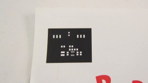
Now use a laser printer to print the color inverse of the top stencil mask onto a piece of magazine paper. Use the highest toner darkness. The color inverse means you want the stencil masks to be white, and the rest to be black. After etching, the solder masks will become holes in the sheet, thus creating a ‘stencil’.
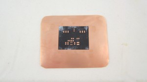
Now use the toner transfer method to transfer the print to the copper sheet. There are many online instructions for the toner transfer method, but according to my experience, the following two tips make it really a breeze. 1) Use magazine papers for the printout. Don’t use glossy photo papers — they are expensive and difficult to peel off. Magazine papers work like a charm. 2) Use a GBC laminator for transfer. It’s much, much easier (did I say much?) than a hot iron. Place the printout face down on the copper sheet, and run it through the laminator at least 10 times. Then throw the copper to hot water. After 5 minute you can peel off the magazine paper. Really easy.

Etching

The next step is very important: you need to cover the bare copper surfaces with tape. This includes both the front and the back sides. You don’t want them to be etched out. Of course the tape should not run too much into the region of the printout — you don’t want to cover any solder mask holes that should be etched out.
Now it’s time to throw the thing into an etchant and let the exposed copper be etched out! Instead of Ferric Chloride, I like using the fast solution that consists of one part muriatic acid + two parts hydrogen peroxide. Very cheap in terms of material cost, and very effective. You can get muriatic acid from Lowes. Just be careful: do not let your skin touch it, and do not breath it directly.
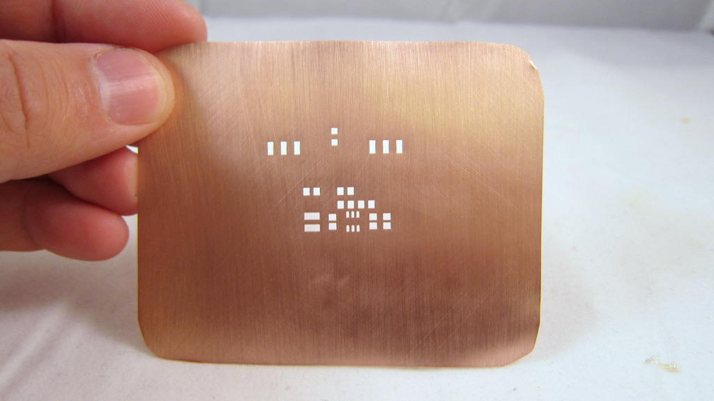
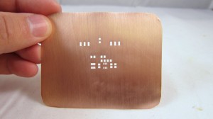
After etching is complete, carefully remove the tapes. Then use Acetone to remove the black toner. Finally, polish the copper surface with a Scotch-Brite scrub sponge. Voila, the solder paste stencil is done! Looks quite pretty.

If you are experienced, the whole process should take no more than 40 minutes. You can make as many stencils as you want. I haven’t tried making a stencil with really small component footprints. I will try that at some point and see how accurate the stencil can be.

Apply Solder Paste

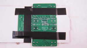
Now it’s time to see some stenciling in action! First, use three spare PCBs to make a tight frame, and insert the target PCB into the frame.
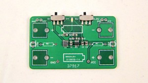
My target PCB today is the AASaver / Breakboard Power Supply. This is a little boost converter that bumps a voltage as low as 0.8V to 5V or 3.3V, which can be used to power bright LEDs or serve as breakboard power supply.
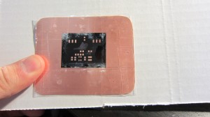
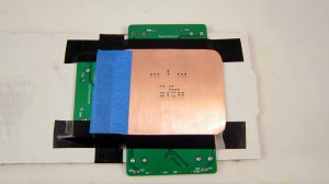
Carefully position the stencil on top of the target PCB, and align the holes with the solder pads. After you are satisfied with the alignment, use a tape to fix the left edge of the stencil. This way, you can easily life the stencil up when you are done, and you don’t have to re-align for the next PCB.
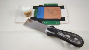
The next step is to apply the solder paste. This is a bit nasty. You need to prepare a putty knife (available in home improvement stores) and some solder paste. I got my solder paste from DealExtreme.com. Cheap and works really well (the only downside is the long shipping time).
I didn’t make a video to show how to apply the solder paste. Fortunately, Sparkfun electronics has a great video tutorial which I included on the left. Check it out!
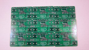
This is the outcome of applying solder paste to nine PCBs. Click on the image to see a zoom-in view. It’s really fast.

Place SMT Components


Placing SMT components onto the PCB is often the trickiest step. These kids are so tiny that even a small breath from your mouth will blow them away. Not only are they difficult to hold still, but it’s tricky to get them out from their packages.

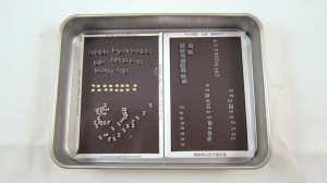
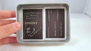
But don’t worry, I found a good way to hold them still so they won’t get lost easily. The method is very simple. Just use some magnets! Most SMT components attract well to magnets. You can 1) easily dump components from their packages to the magnetic surface, and 2) move or even lift up the magnets, and the components won’t fall off. So next time when you travel, don’t forget to buy some extra magnets!

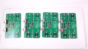
Use tweezers to carefully move components from the magnets to the PCBs, and place them in the right spots. Here is the outcome of SMT placement.

As some point I will need to buy a pick and place machine to automate this step.

Hot Skillet Reflow


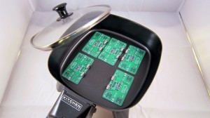
Now it’s time for some hot skillet action. Place several component populated PCBs into an electric skillet. Turn to the maximum power. In about 2-3 minutes the reflow will start to happen. As soon as it’s done, turn off the power and let the PCBs cool down. If you’ve never done the reflow before, check out Sparkfun’s awesome Reflow Skillet tutorial.

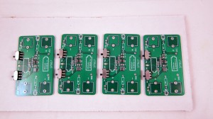
You should do this outdoors because the fumes produced during reflow are toxic, and you certainly don’t want to breathe them! The picture on the left shows the outcome of the reflow.

Lastly, perform careful visual checking to see if every component is soldered properly. Also do a basic electric test to see if the circuit functions correctly.

The Final Result

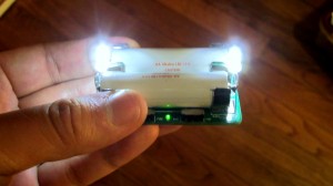
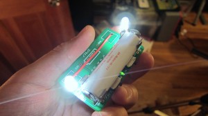
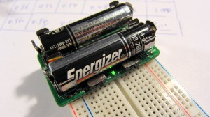
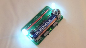
Here you are, a fully functioning AA Saver / Breakboard Power Supply! I will write another blog article shortly to introduce this small yet very useful circuit. Stay tuned.