How to Switch Gardena 1251 Latching Valve using OpenSprinkler Bee (OSBee)

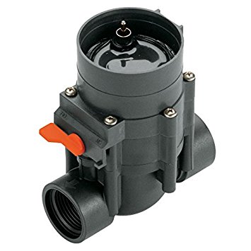
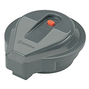
Recently when helping a customer, I came across an interesting case of how to control Gardena 1251 latching solenoid valve using OpenSprinkler Bee. This valve is mostly sold in the European market and isn’t very popular in the US market. On spec, it’s operated using a single 9V battery, and to use this valve you need to buy a Gardena 1250 controller unit. The whole assembly including the valve and controller unit are quite pricy (close to 100 bucks), so it’s not a very cost-effective solution compared to other brands. Nonetheless, it’s an interesting case that helped me understand how these latching solenoids work.


Measure the Control Voltages

The initial request to look into this valve was due to the fact that OSBee can’t seem to operate this valve correctly: it can open the valve but never manages to close the valve. This was reported by a German customer, and it caught my curiosity. To figure out the issue, the first thing I did was to check how the control unit (1250) is sending out control voltages to the valve. It’s pretty common that when operating latching solenoid valves, the control circuit sends an impulse voltage to open the valve, and another impulse voltage in the reverse polarity to close the valve. On most solenoid valves I’ve seen, the two impulse voltage (of opposite polarity) are roughly the same, and that’s also how the OSBee circuit works.

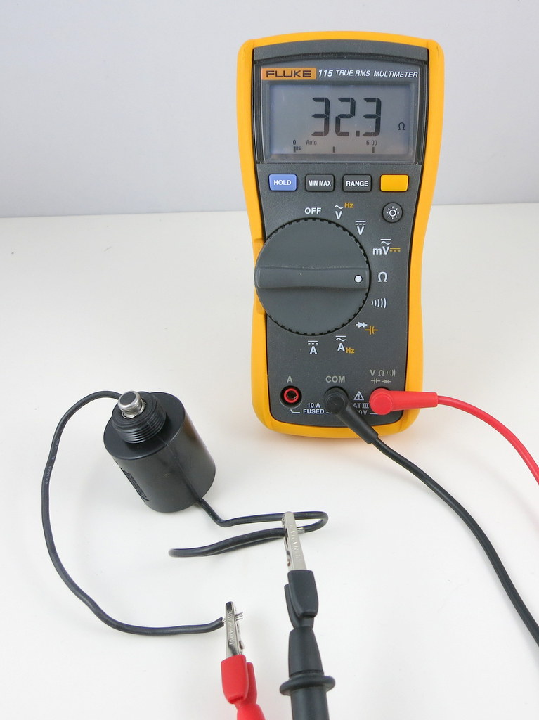
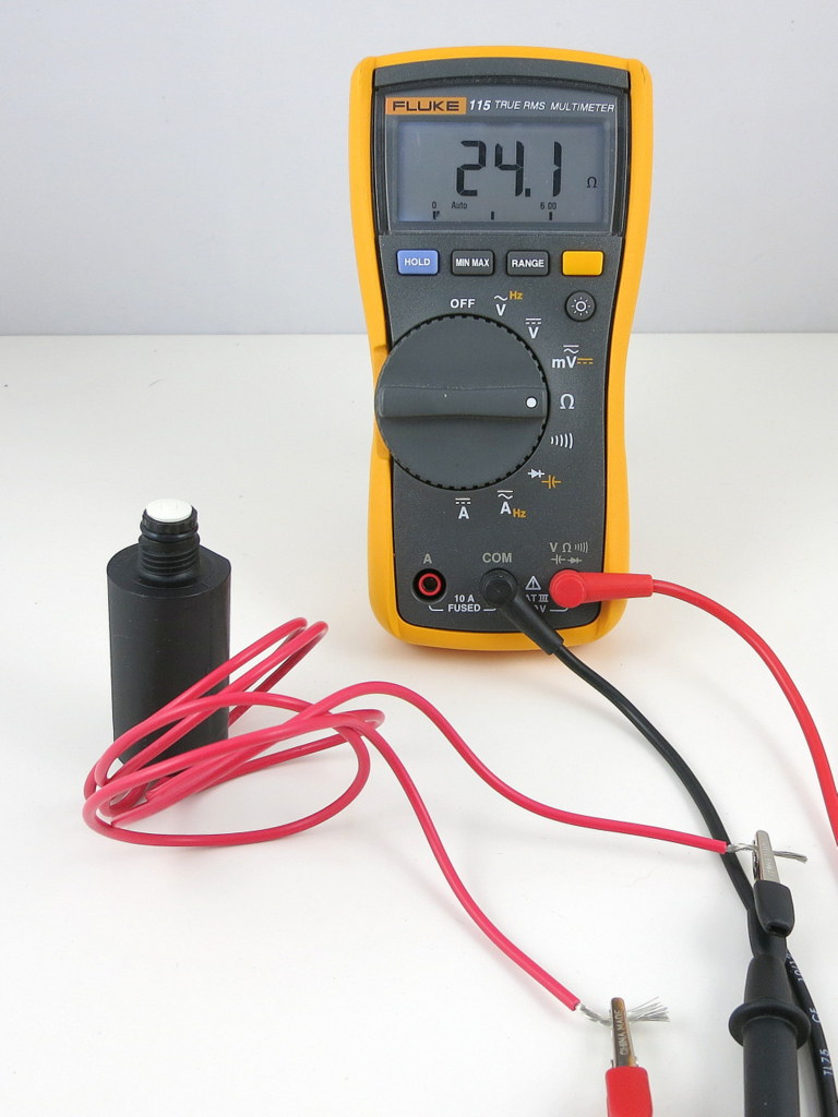
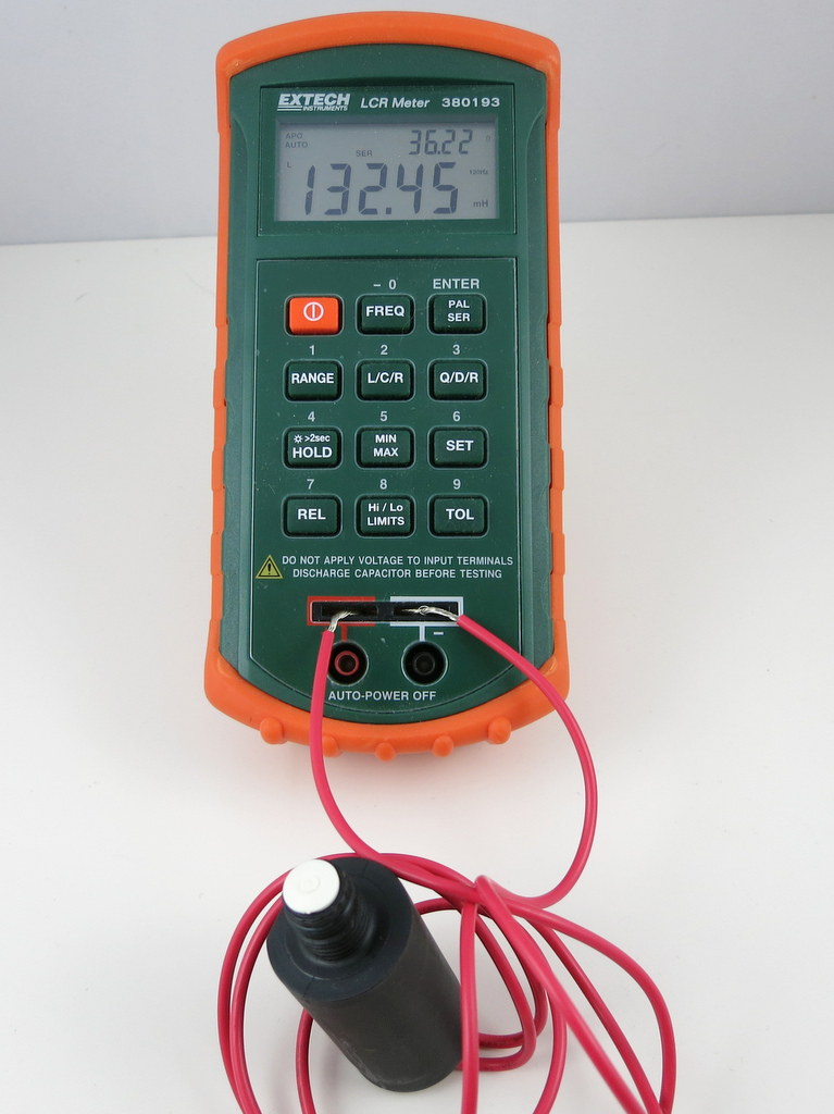
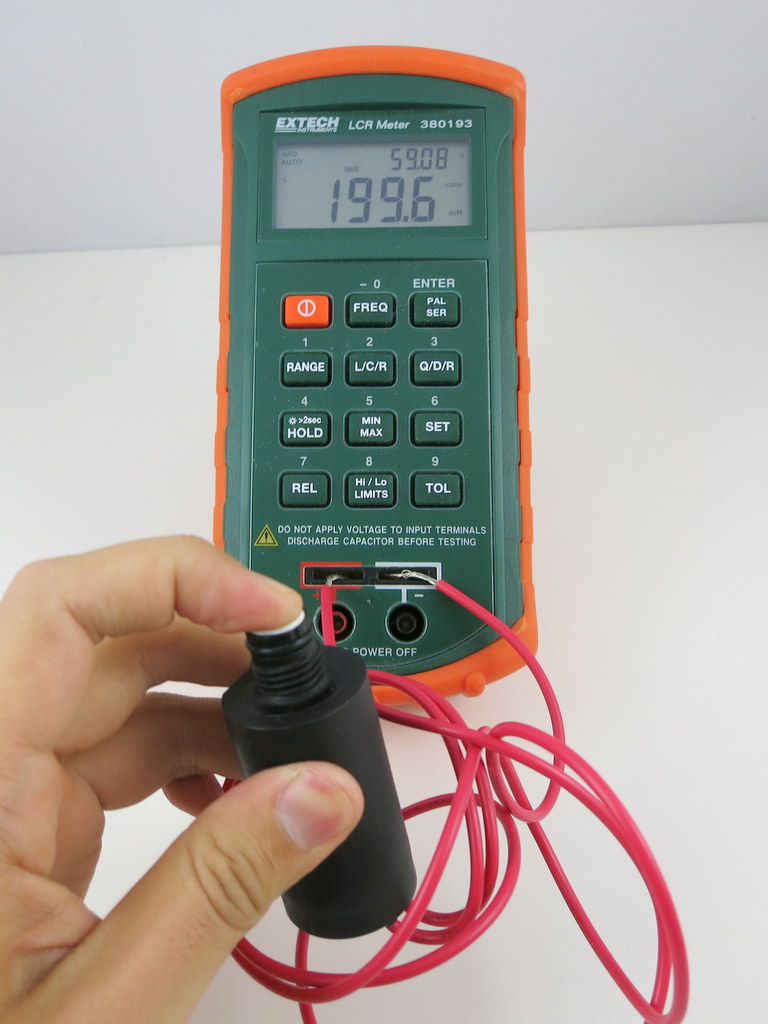
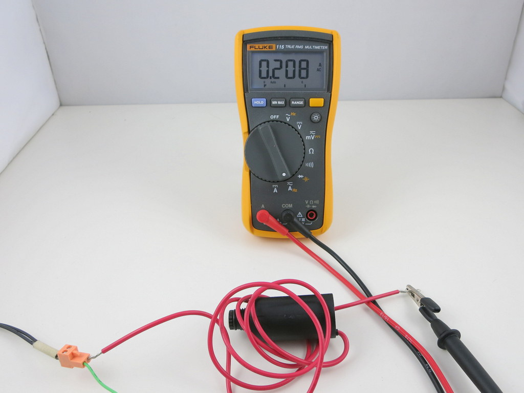
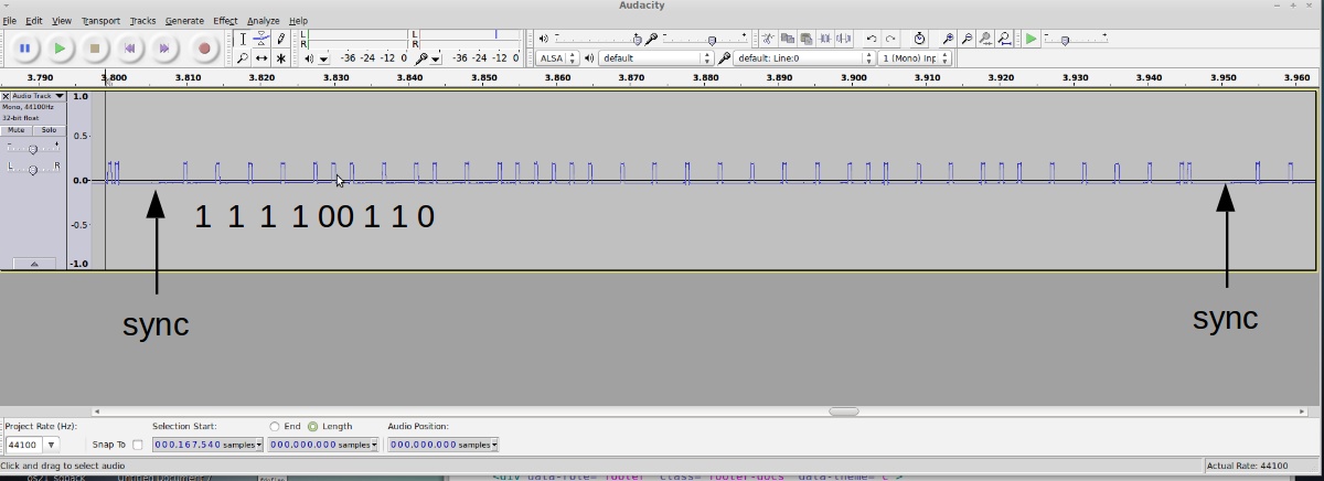
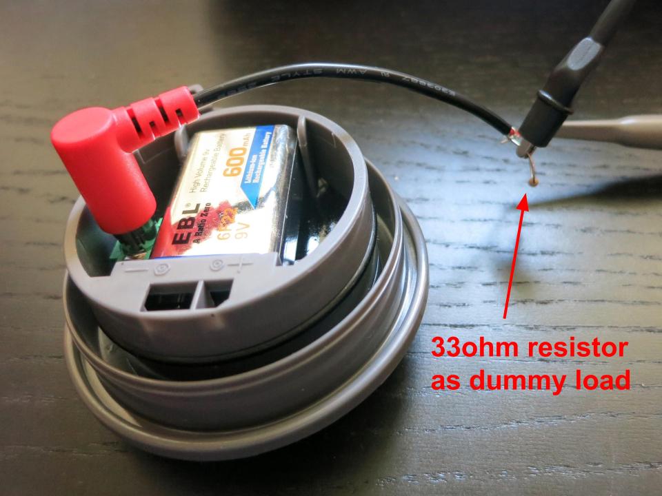
Upon connecting the control unit to an oscilloscope, I noticed something strange: no matter how I press the on/off button, it’s only sending a very short (a few milliseconds) pulse, which cannot possibly operate the valve. Then it became clear to me that the controller is in fact actively sensing the existence of the valve, and would not send control voltages if the valve is not detected. I measured the resistance of the solenoid valve, which is about 35 ohm. So I connected a 33 ohm resistor to the controller as a dummy load, and there you go, now we can observe the control voltages and pulse lengths.

It’s pretty easy to notice the asymmetry here: while opening the valve requires a pulse of 250 ms and -7.84 voltage (this is roughly the battery voltage since my 9V battery isn’t fully charged), closing the valve only requires a very short pulse of 62 ms and very low voltage — 2.5V. This is quite strange to me: how come closing the valve only requires such a short pulse and such low voltage?


How Does This Latching Valve Work?

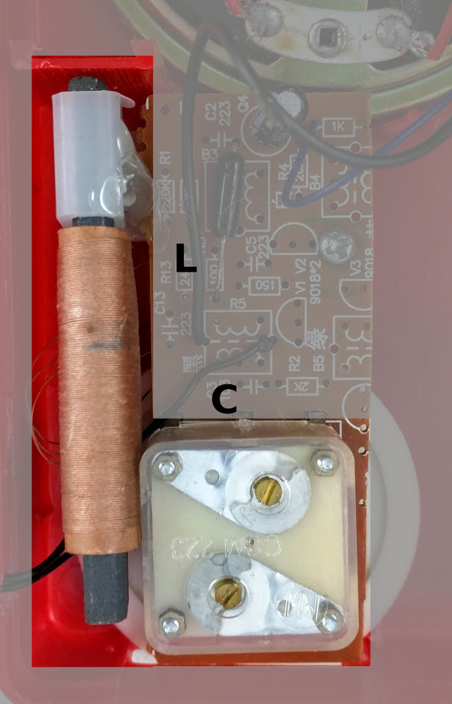
In order to figure out what’s going on here, I un-tightened a bunch of screws and opened up the valve.

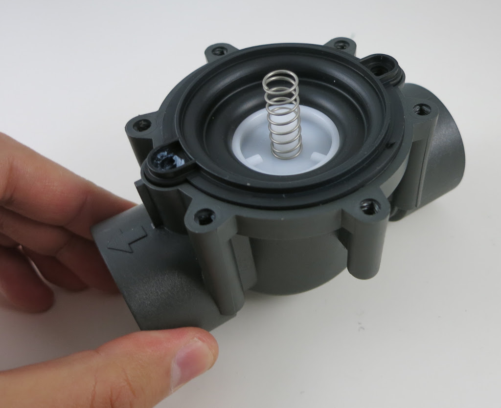
At the bottom of the valve is a pressure chamber with a spring. This is very similar to other valves I’ve seen.

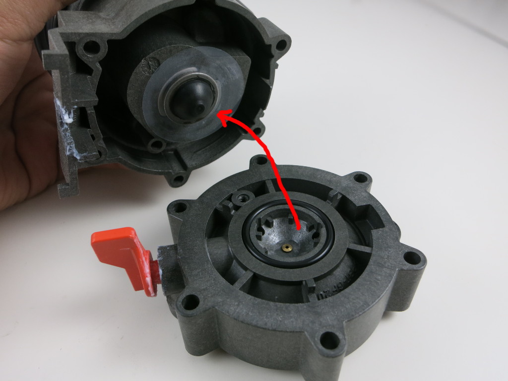
The top section contains, supposedly, a coil and magnet inside, and a small cone-shaped metal piece that can be attracted to the magnet or released. It’s quite easy to observe that when opening the valve, the metal piece gets attracted (left picture above), this supposedly releases the pressure in the bottom chamber, thus allowing the water to flow through the valve. Conversely, when closing the valve, the metal piece is released and dropped to block the hole at the bottom, this supposedly allows water pressure to build up in the bottom chamber, thus stopping the water flow.

The key in making this latching is that an impulse voltage can permanently magnetize the core, thus permanently attracting the metal piece. This makes it possible for the valve to remain in the ‘open’ status without contiguously drawing current from the power source (which is unlike non-latching valves like 24VAC valves).

Observing this mechanism, it became clear to me that ‘closing’ the valve basically requires de-magnetizing the core, and that requires just a short pulse of low voltage in the opposite polarity. If you apply the same voltage and strength as before, it will start magnetizing the core the other way, thus the magnetic pole changes direction but the metal piece will still be permanently attracted!

Anyways, this is very interesting to me because previously I had no idea how latching solenoid valves work internally. Now at least I know understand this particular valve works, and this understanding will help me figure out how to get OpenSprinkler Bee to control this valve.


Use OSBee to Control the Gardena 1251 Valve

There are several issues that make OSBee incompatible with the Gardena 1251 valve, but it turns out they can all be solved without too much difficulties. The first is that OSBee by default boost the input voltage (which is 5V from USB) up to 22VDC, which is significantly higher than 9V required by the valve. This is reasonably easy to solve — by fine tuning the boosting time, I can find the sweet spot where the boosted voltage is just around 9V. This boosting time turns out to be around 80 to 100ms.

Second, OSBee by default uses 100ms pulse in both directions (i.e. both opening and closing the valve). This is very easy to change to 250ms and 62ms respectively to match the Gardena controller.

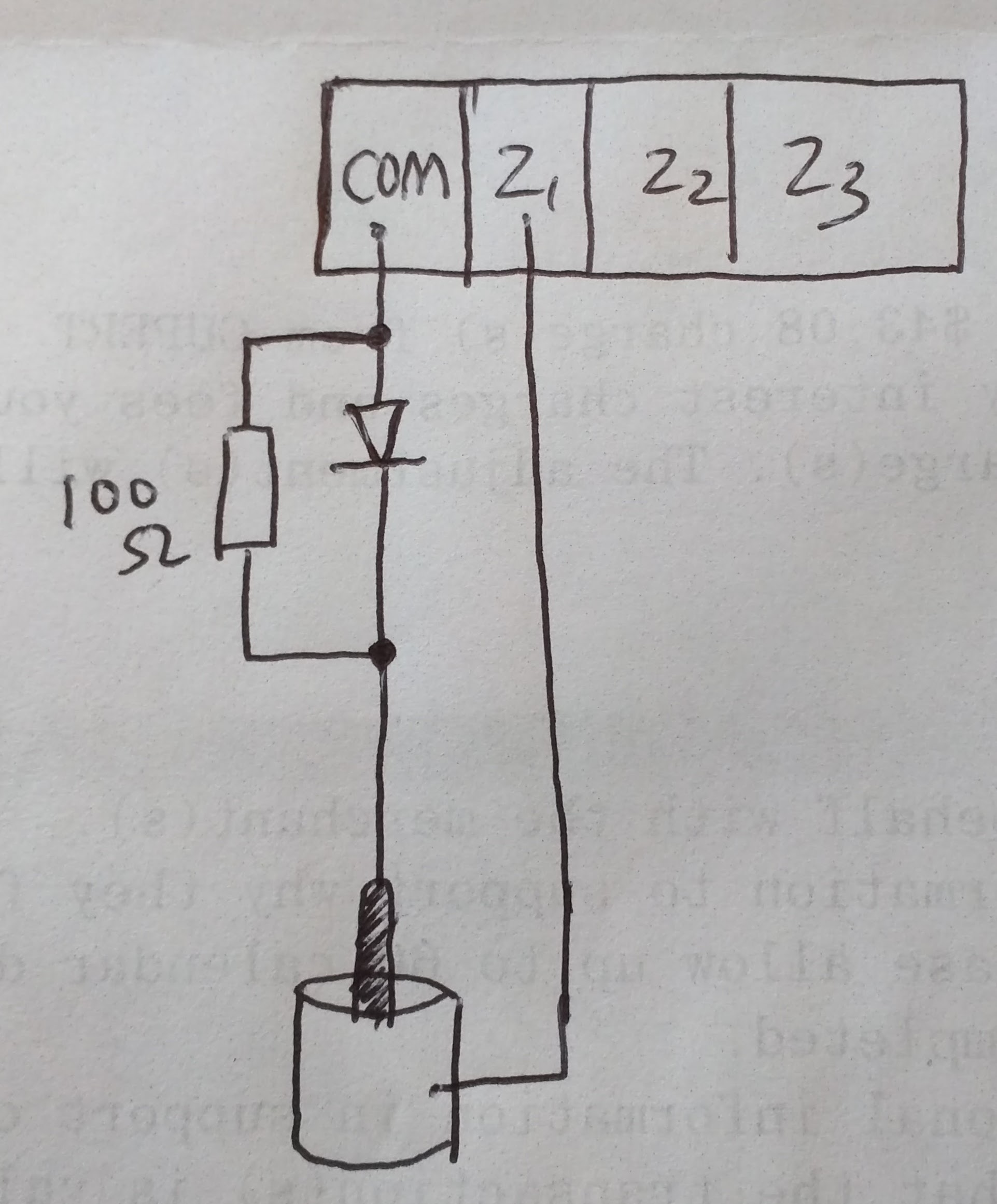
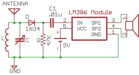
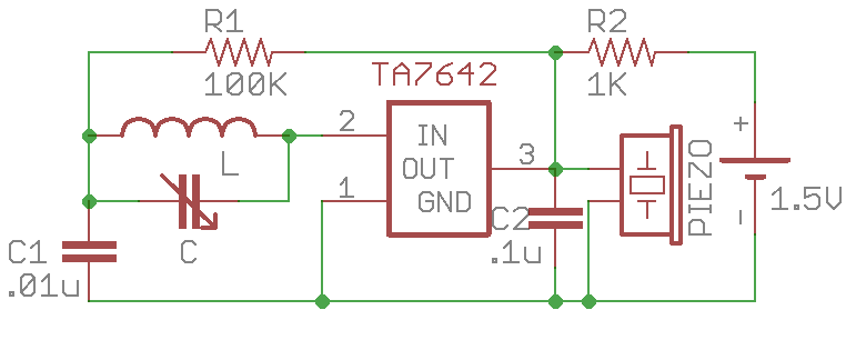
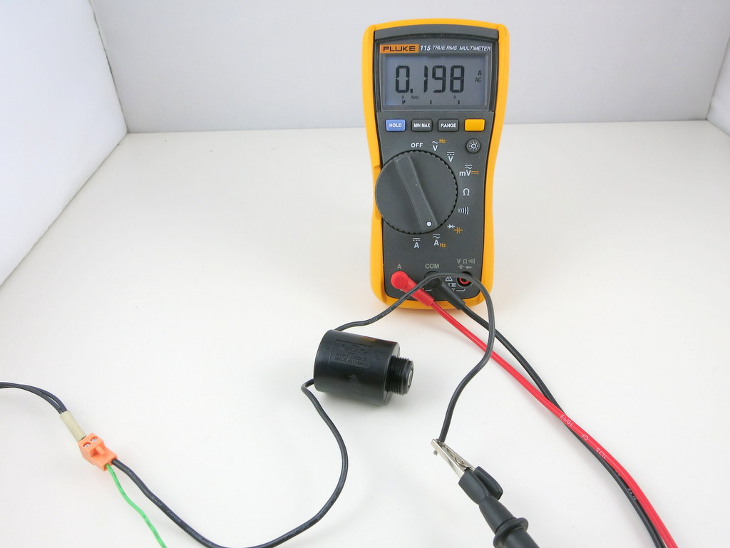
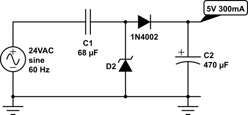
The last issue deserves more thinking, that is, opening the valve requires 9V, but closing the valve requires only 2.5V. Because the input voltage is from USB and it’s 5V, there is no obvious way to step that down to 2.5V since the boost converter can only bump up the voltage and never reduce the voltage. How do we create this asymmetric voltage in opposite polarities? Turns out that you can do so by making use of a diode connected in parallel with a 100 ohm resistor. Why? The diode is a one-way gate: when positively biased, it turns on almost fully (except the 0.7V voltage drop across it, which can be ignored here); but when reversely biased, it turns off, thus current has to flow through the resistor (connected in parallel to the diode), and that resistor will divide the voltage, ensuring that only about 2.5V falls on the valve.

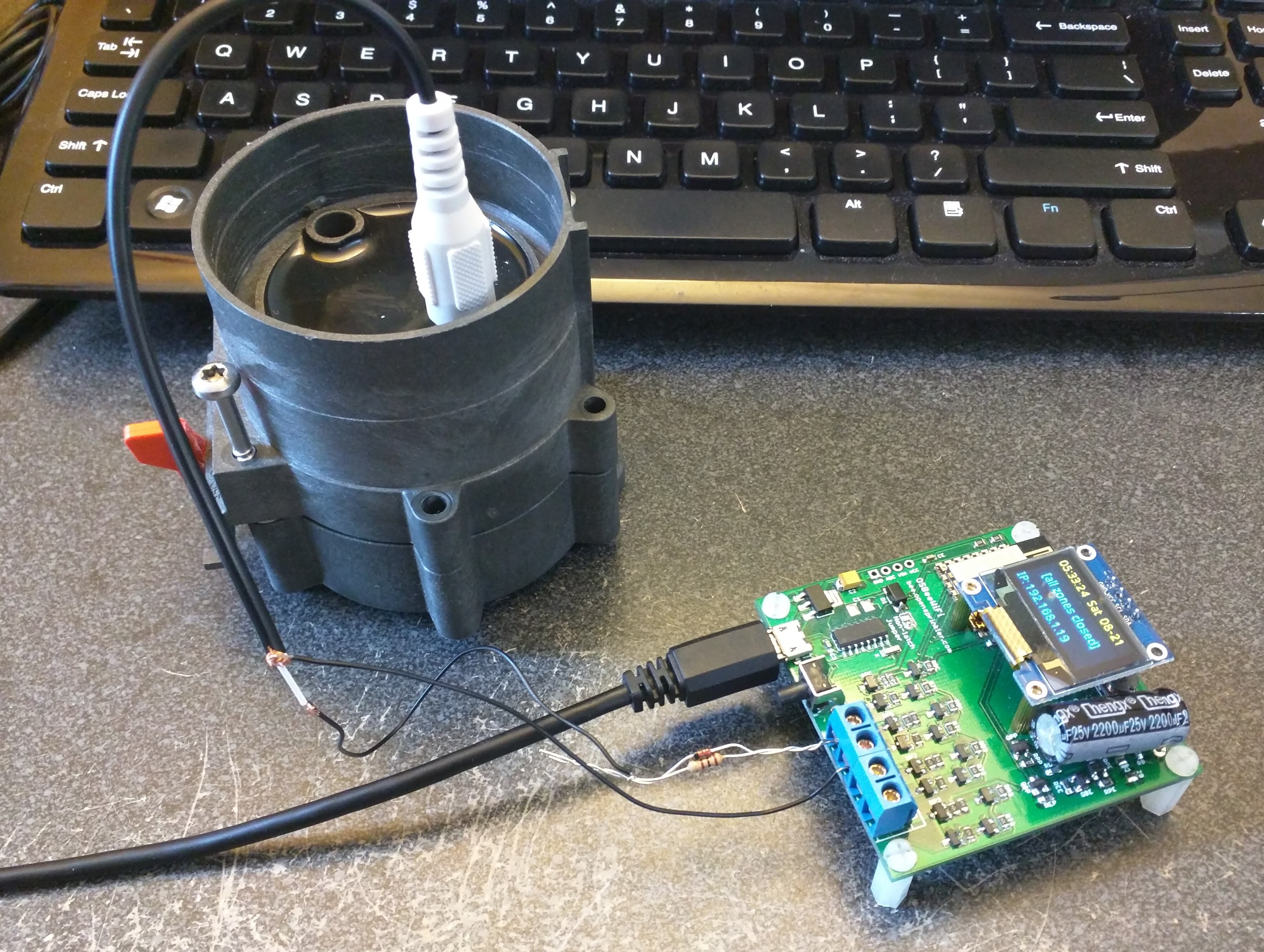
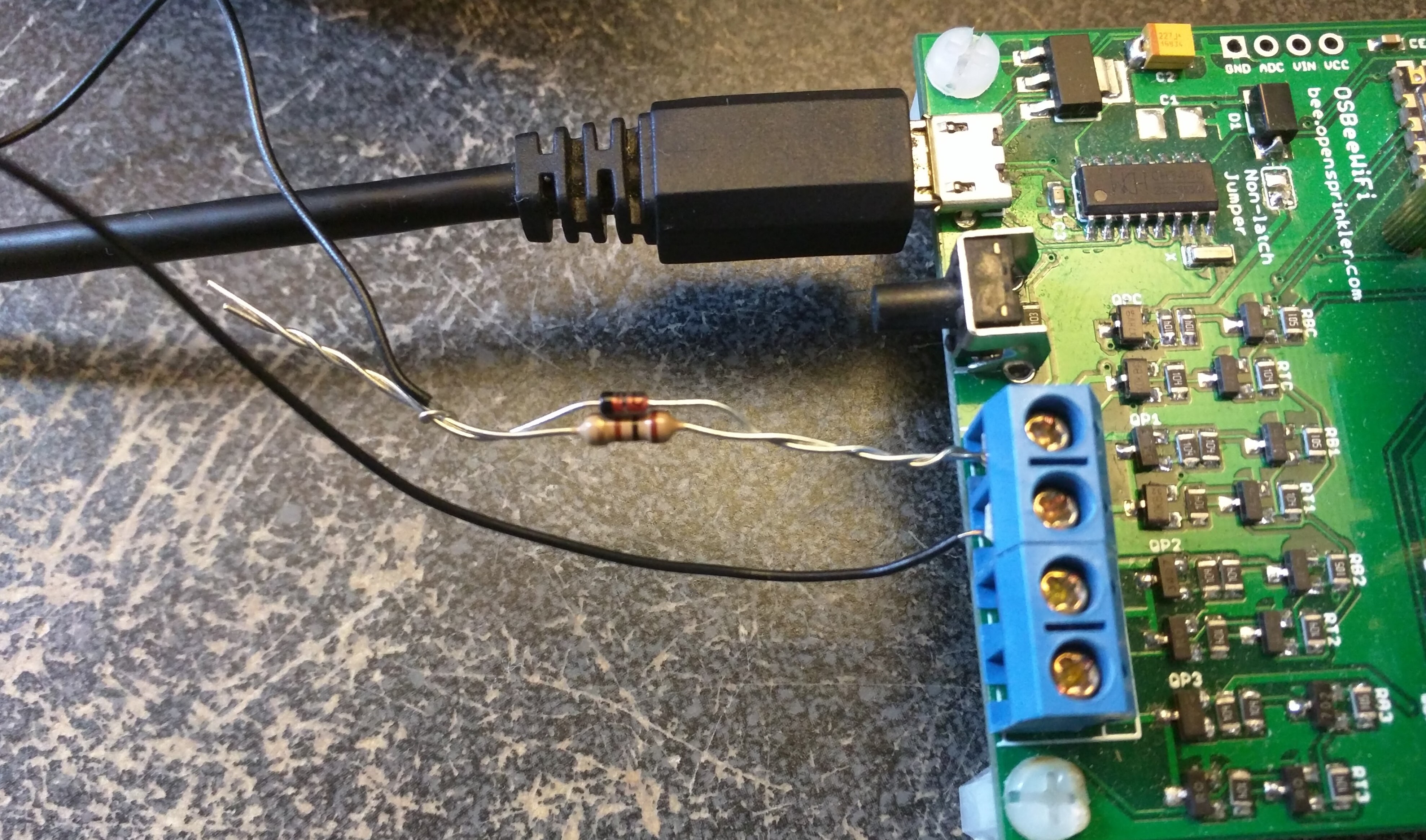
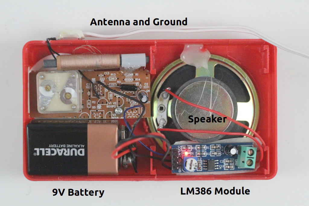
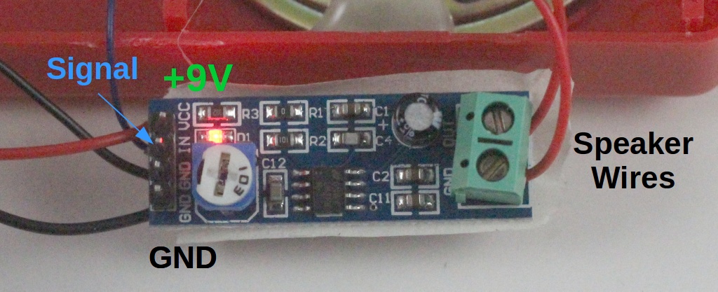
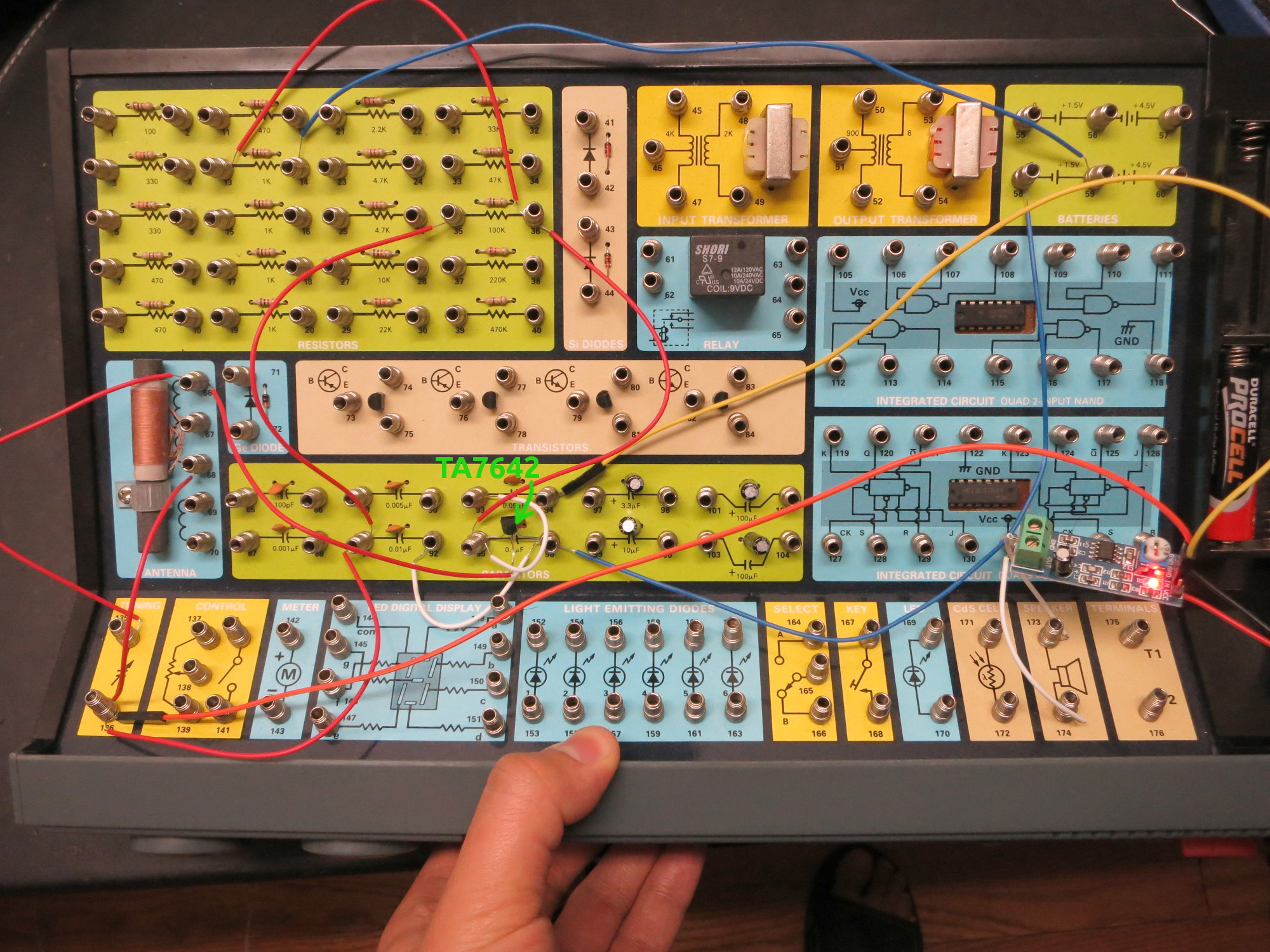
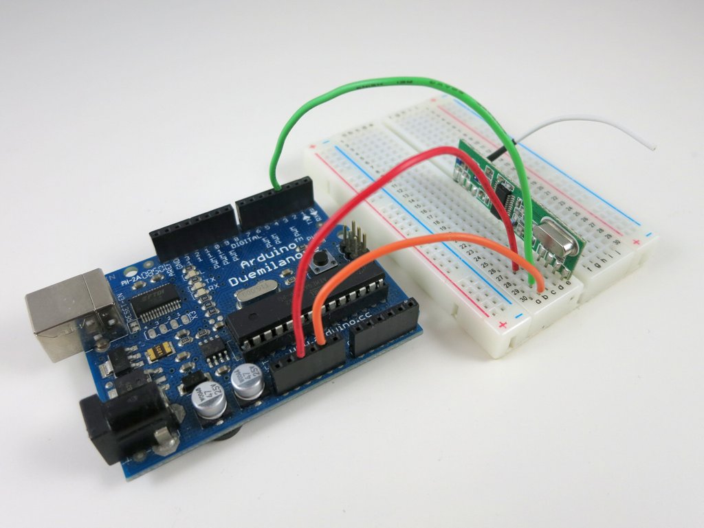
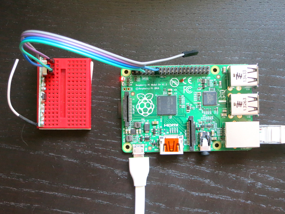
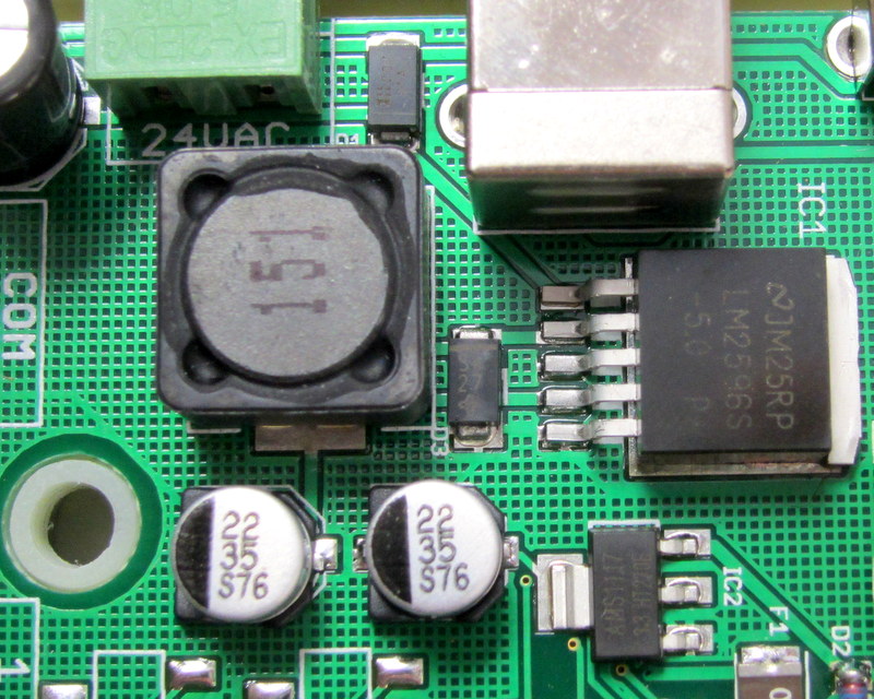
I’ve attached here a diagram showing the connection. The diode can be almost any general-purpose rectifier, like 1N4148, 1N4001 and so on. I’ve also included two photos showing the actual components connected to OSBee and the valve. With this modification, OSBee can now both open and close the Gardena 1251 valve successfully. Mission accomplished!

Learning Electronics — 2. Fun with Crystal Radio and Extensions

As a kid I was fascinated by the Crystal Radio — the simplest radio that requires no battery or power source. Learning about crystal radio is what got me into electronics in the first place. There are plenty of tutorials you can find online about how to build your own. In this blog post I describe a basic version of the crystal radio, and a couple of simple extensions using modern techniques to improve its quality (although these extended versions all require battery). I won’t talk much about the principles, but instead will focus on making it easily reproducible and a fun weekend project.

(By the way, this is the second of the ‘Learning Electronics’ series. The first one was about the Astable Multivibrator circuit and was posted five years ago… Alas, time flies!)

The Basic Version
The basic version of crystal radio that I learned as a kid consists of just 7 components as shown below. In fact, the resistor R is optional, making it only 6 components. There is an inductor L, variable capacitor C, diode D, high-impedance earphone (you can use a piezo disc), and antenna and ground. The amazing thing about this circuit is that it has no battery or power source, as the radio signal directly drives the earphone.

crystalradio_basiccrystalradio_lccrystalradio_pd

Because radio signals are very weak, to make it successful, there are several key ingredients:

crystalradio_gnd

  • Earphone: you have to use a high-impedance earphone — the typical earbud has very low impedance (less than 32 ohm), which is too heavy a load to drive with direct radio signals. The easiest solution is to use a piezo disc, which has very high impedance and is very cheap. You can then use a thick paper (or better, 3D printing!) to make a cone cover so that you can easily insert it into your ear.
  • Diode D: use a diode with small forward drop voltage. The classic choice is a Germanium diode, such as 1N34A or 1N60. However, Germanium diodes are difficult to source these days. So if you can’t find a Germanium diode, a small Schottky diode like the common 1N5817 would also work. Again, the point is to use a diode with the smallest forward drop voltage possible.
  • Antenna and Ground: a good antenna is critical for crystal radio. The antenna should be set up outdoors if possible. I implemented mine using a long single stranded wire and ran it around the perimeter of my porch. It worked quite well. As for ground, I just inserted a wire into the ground hole of a 3-prong wall socket. Be careful: make sure it stays reliably in the ground hole. If the wire touches the hot socket, it will be extremely dangerous!
  • Tuning Circuit: inductor L and variable capacitor C form the tuning circuit. These are pretty easy to find in an old radio or a DIY radio kit (as shown in the picture above). A lot of the inductor coils you can find have both a primary coil and secondary coil. You can use just the primary coil, or connect the primary and secondary in series. Similarly, a lot of the variable capacitors have two sections. You can use either section, but to help increase the frequency range of reception, you can connect the two sections in parallel.

The best time to try the crystal radio is probably at night, when there is less electro-magnetic interference in the air and the ambient noise is low. Slowly turn the dial on the variable capacitor and listen carefully. If there is a strong local AM station, you should be able to hear it. If you can’t hear anything, don’t worry, read on and you can find how to use a simple audio amplifier module to help you hear weak channels.


LM386 Audio Amplifier Module
The first time I heard something from the crystal radio, it was really exciting. But the volume is just too small to keep enjoying it. After a bit of Googling, I found a simple audio amplifier chip LM386, which can easily amplify the radio signal to be played on a speaker. It’s pretty easy to build the circuit myself, but there are ready-made LM386 modules that you can find on eBay and Amazon, for only a couple of bucks. So I bought one. Soldered a few wires, connected a standard 8 ohm speaker, and plugged in a 9V battery: wow, now you can hear the radios loud and clear, much better! Below is the updated schematic and a picture showing the wiring:

crystalradio_lm386crystalradio_lm386pic

crystalradio_lm386closeup


TA7642 Radio IC
With LM386, the sound is loud and clear. But there is still one problem: the antenna and ground wires are very cumbersome, and make the circuit non-portable. I did some more Googling, and found a simple radio IC called TA7642 that can amplify and detect AM signal, eliminating the antenna and ground wires. TA7642 is a 3-terminal IC shaped like a transistor. It’s quite simple to use and can work at a voltage as low as 1.2V, which is ideal for battery power. You can buy it from eBay or Amazon. I got mine from the Chinese website Taobao, for a jaw-dropping price of 20 Chinese cents (about 3 US cents). Below is a typical circuit of TA7642 that works with high-impedance earphone. It is powered by a single AA battery:

ta7642_simple

This time the antenna and ground wires are gone, so the circuit becomes portable. To hear the sound through a speaker, you can again use the LM386 audio amplifier. Because LM386 requires at least 5V, it won’t work with a single AA battery. But it’s common to use a 9V battery to power the whole circuit, and two diodes in series to create the 1.5V operating voltage that TA7642 needs.

I implemented the circuit using an electronic experiment kit, which has most of the components I needed. I can easily make a custom PCB to fit everything in a small enclosure. At night I can hear about 3 to 4 stations. Cool!
ta7642_pic

DIY Radio Kit: so after I built the circuit, I discovered that Elenco sells a $15 DIY Radio Kit that is essentially the same circuit as I learned above (i.e. TA7642 + LM386). So if you want a kit that includes all the components, this is a very decently priced kit to buy.

Along my search, I also found some DIY Radio Kits from Taobao, like this six-transistor radio, and seven-transistor radio. For less than $2, these kits include PCB, all components, speaker, and even an enclosure! What a crazy price!


It was a lot of fun to re-live my childhood passion by learning to build the crystal radio again, with some modern touches. The experiments above are quite easy to reproduce, and hopefully they provide inspirations for you to try them out as well.

Understanding 24VAC Sprinkler Valves

Note: check out our OpenSprinkler DC-powered version, which uses an innovative circuit design that drives sprinkler solenoids using DC-only voltage.

I often get questions about sprinkler valves, so in this post I will explain the basic electric properties of sprinkler valves. If you are designing a sprinkler controller circuit, understanding these properties can be helpful. It’s a common mistake to assume sprinkler valves work with DC voltage. While most valves indeed CAN be powered by DC voltage (see below), they are designed to work with AC voltage in the range of 22VAC to 28VAC. That’s why if you look at a standard sprinkler transformer, the output is usually AC.

The electric part of a sprinkler valve is the solenoid — it’s a cylindrical-shaped thing screwed into the valve. At the center of the solenoid is a rod supported by a spring. The solenoid has two wires connected to its internal coil. Applying 24VAC on the two wires energizes the coil, and causes the rod to contract into the solenoid. This releases the internal water pressure thus opening the valve, allowing water to flow through the valve. Removing the voltage causes the rod to revert back to its original position. This allows the water pressure to build up internally hence stopping the flow. Because closing the valve relies on internal pressure build-up, it usually takes a few seconds to completely stop the water flow. This also means if your water pressure is too low you may not be able to completely stop the water flow.

IMG_0205IMG_0206

Let’s start by measuring the resistance of the sprinkler solenoid. I have two example solenoids, one made by Orbit and one made by Hunter. According to the multimeter, one measures 32.3 ohm, and the other measures 24.1 ohm. So the resistances are pretty low. If you think about it for a while, you might realize something is not quite right here: if we apply 24V on the solenoid, wouldn’t that produce a 24 V / 24.1 ohm = 1 amp current draw? That’s quite steep. In fact, my sprinkler transformer is only rated 750 mA output current, so it can’t provide enough current to drive even one solenoid?!

The catch is exactly in the fact that sprinkler solenoids are powered by AC voltage. Because the solenoid is made of a coil, it not only has coil resistance but also inductance. When operated on AC power, the inductance produces significant reactance which cannot be ignored. You can read the Wikipage to find out how reactance is calculated, but basically it has to do with the frequency of the input voltage, and the inductance of the coil. Because inductors ‘prevent’ current from changing rapidly, it behaves like a ‘resistor’ under changing current (i.e. AC). The higher the frequency, the higher the ‘resistance’ (i.e. reactance).

With an LCR meter, I measured the inductance of the two solenoids:
IMG_0207IMG_0209
One reads 63.57 mH, the other 132.45 mH. So if we power the solenoids by 24VAC, 60Hz, which is the standard output of a sprinkler transformer, we will get a reactance of:

This, plus the resistance, gives a total impedance of:

Note that the reactance counts into the imaginary part of the impedance. Using complex numbers is just a convenient way of denoting not only the magnitude but also the phase. For example, when you apply a sinusoid voltage on the inductor, the corresponding current is also a sinusoid wave, but with a different phase. Using complex numbers, the calculation can be carried out quite easily.

Now we can calculate the operating current under 24VAC (rms). We only care about the magnitude, so the current (rms) would be:

OK, so this is getting closer to the reality. But 0.6 amp current still sounds high. What is missing? Well, remember that when the solenoid is activated, the rod will be attracted into the solenoid, and that can change the inductance significantly. So let’s re-measure the inductance with the rod pushed in:

IMG_0208IMG_0210

Indeed the inductance jumped from 63.57 mH and 132.45 mH previously to 194.4 mH and 199.6 mH respectively. OK, now if we redo the calculations, we will find out that the correct reactance is:

and current (rms) os:

The resulting current is about the same on the Hunter solenoid. So this roughly matches the electric specification of a typical sprinkler valve. It’s actually still a bit off: if we measure the actual AC current flowing through the solenoid:
IMG_0211IMG_0212

The readings are about 0.2 amp. I suspect the difference comes from the measurement of the inductance. On my LCR meter, which can measure inductance at two frequency levels: 120 Hz and 1 kHz, I find that the inductance is measured differently under the two frequencies. Because the actual operating frequency of the solenoid is 60 Hz, and my meter cannot measure 60 Hz, the inductance I am getting is probably somewhat off. That should explain the difference between the calculation and the actual current reading.

The 0.6 amp current we calculated above probably explains the inrush current: when the solenoid is just energized, there is an impulse current that’s typically higher than the holding current. This is because the rod is still out, and hence the reactance is lower, causing a higher current than when the rod is attracted in.

Operating Sprinkler Valves Under DC

Note: check out our OpenSprinkler DC-powered version, which uses an innovative circuit design that drives sprinkler solenoids using DC-only voltage.

From the calculations above, it’s obvious that the coil inductance is important at limiting the operating current when the valve is powered under AC. What about if we power the valve under DC? Obviously we shouldn’t use 24VDC, because that would draw too much current (0.75 to 1 amp). If you search online, you will find plenty of posts talking about powering sprinkler valves using 12VDC. This actually works well in general. Using 12VDC has advantages in that 12VDC power adapters are cheaper and much easier to find; the circuit design is simpler, and you can use the same circuit to interface with other DC devices like relays and motors. In contrast, 24VAC power circuits are more complex and you can’t use the same circuit to directly interface with DC devices.

However, you should be aware that because the sprinkler solenoid’s resistance is pretty low, the operating current under 12VDC will be relatively high, around 400 to 500 mA. This more than doubles the 200 mA operating current (rms) under 24VAC. Also, the coil will heat up more, and this potentially shortens its life. For example, under 12VDC, the Orbit valve above will dissipate 12 * 12 / 32.3 = 4.5 Watt; whereas under 24VAC, the same valve only dissipates 0.2 * 0.2 * 32.3 = 1.3 Watt (note that only the resistive portion dissipate power, inductive portion does’t).

Again, the issue is that under DC there is no reactance, so the coil’s inductance plays no effect at limiting the current. What if we reduce the voltage further to 9VDC, in order to reduce the operating current? After all, the solenoid only needs 200mA holding current to remain activated. Unfortunately that won’t work: I’ve tried powering solenoids with 9V, and I can’t get the valve to reliably energize. The problem is that 9V is not sufficient to provide the required inrush current, so the rod cannot get fully attracted in. However, if the rod is already in, 9V is sufficient to hold the solenoid activated. So if you really want to make it work with 9V, you need a circuit that can provide a high impulse voltage; then once the solenoid is activated, you can lower the voltage to reduce the current (hence power) consumption. A possible solution is to use a boot converter (very much similar to circuits for latching solenoids) to provide an impulse high voltage, but this comes at the cost of increased circuit and software complexity.

Reverse Engineer a Cheap Wireless Soil Moisture Sensor

At the Maker Faire this year I got lots of questions about soil moisture sensors, which I knew little about. So I started seriously researching the subject. I found a few different soil sensors, learned about their principles, and also learned about how to make my own. In this blog post, I will talk about a cheap wireless soil moisture sensor I found on Amazon.com for about $10, and how to use an Arduino or Raspberry Pi to decode the signal from the sensor, so you can use it directly in your own garden projects.

IMG_0183

What is this?
A soil moisture sensor (or meter) measures the water content in soil. With it, you can easily tell when the soil needs more water or when it’s over-watered. The simplest soil sensor doesn’t even need battery. For example, this Rapitest Soil Meter, which I bought a few years ago, consists of simply a probe and a volt meter panel. The way it works is by using the Galvanic cell principle — essentially how a lemon battery or potato battery works. The probe is made of two electrodes of different metals. In the left picture below, the tip (dark silver color) is made of one type of metal (likely zinc), and the rest of the probe is made of another type of metal (likely copper, steel, or aluminum). When the probe is inserted into soil, it generates a small amount of voltage (typically a few hundred milli-volts to a couple of volts). The more water in the soil, the higher the generated voltage. This meter is pretty easy to use manually; but to automate the reading you need a microcontroller to read the value.

IMG_0180IMG_0182

Resistive Soil Moisture Sensor
Another type of simple soil sensor is a resistive sensor (picture on the right above). It’s made of two exposed electrodes, and uses the fact that the more water the soil contains, the lower the resistance between the two electrodes. The resistance can be measured using a simple voltage dividier and an analog pin. While it’s very simple to construct, resistive sensors are not extremely reliable, because the exposed electrodes can degrade and get oxidized over time.

Capacitive Soil Moisture Sensor
Capativie soil sensors are also made of two electrodes, but insulated (i.e. not exposed). The two electrodes, together with the soil as a dielectric material, form a capacitor. The higher the water content, the higher the capacitance. So by measuring the capacitance, we can infer the water content in soil. There are many ways to measure capacitance, for example, by using the capacitor’s reactance to form a voltage divider, similar to the resistor counterpart. Another way is to create an RC oscillator where the frequency is determined by the capacitance. By counting the oscillation frequency, we can calculate the capacitance. You can also measure the capacitance by charging the capacitor and detecting the charge time. The faster it charges, the smaller the capacitance, and vice versa. The Chirp (picture below), which is an open-source capacitive soil sensor, works by sending a square wave to the RC filter, and detecting the peak voltage. The higher the capacitance, the lower the peak voltage. Capacitive sensors are not too difficult to make, and are more reliable than resistive ones, so they are quite popular.

chirp

More Complex Soil Sensors
There are other, more complex soil sensors, such as Frequency Domain Reflectometry (FDR), Time Domain Reflectometry (TDR), and neutron sensors. These are more accurate but also will cost a fortunate to make.

Wireless Soil Moisture Sensor
Because soil sensor is usually left outdoors, it’s ideal to have it transmit signals wirelessly. In addition, because soil moisture can vary from spot to spot, it’s a probably good idea to use multiple sensors distributed at different locations to get a good average reading. Wireless would make it more convenient to set up multiple sensors.

Recently I found this 433MHz wireless soil sensor from Amazon, for only $10, very cheap. It comes with a transmitter unit and a receiver display unit. The transmitter unit has a soil probe. The receiver unit has a LCD — it displays soil moisture level (10 bars) and additionally indoor / outdoor temperature. Let me open up the transmitter to see what’s inside:

IMG_0177IMG_0178IMG_0179IMG_0181

There is a soil probe, a 433MHz transmitter, a microcontroller at the center, a thermistor, and a SGM358 op-amp. Pretty straightforward. The soil probe looks quite similar to the battery-free soil meter probe that I mentioned above. So I am pretty sure this is not a resistive or capacitive probe, but rather a Galvanic probe. Again, the way it works is by outputting a variable voltage depending on the water content in soil. By checking the PCB traces, it looks like the op-amp is configured as a voltage follower, which allows the microcontroller to reliably read the voltage generated by the Galvanic probe.

Now we understand the basic principle of the sensor, let’s take a look at the RF signal from the sensor. I’ve done quite a few similar experiments before, so I will just follow the same procedure as described in this post.

Raw Waveform. To begin, I use a RF sniffing circuit to capture a raw waveform, which looks like this:

soil_waveform

Encoding. Each transmission consists of 8 repetitions. The above shows one repetition: it starts with a sync signal (9000us low); a logic 1 is a impulse (475us) high followed by a 4000us low; a logic 0 is the same impulse high followed by a 2000us low. So the above signal translates to:

11110011 01100000 11111111 00111001 1111

The signal encodes both temperature and soil humidity values. By varying temperature and soil moisture, and observing how the signals change, it’s pretty easy to figure out that the 12 bits colored blue correspond to temperature (10 times Celcius), and the 8 bits colored red corespond to the soil moisture value. The first 12 bits are device signature, which is quite typical in this type of wireless sensors; the last four bits are unclear, but likely some sort of parity checking bits for the preceding four bytes). So the above signal translates to 25.5°C and a soil moisture value of 57.

The display unit shows soil moisture level in 10 bars — 1 to 3 bars are classifed as ‘dry’, 4 to 7 bars are classified as ‘damp’, and above 7 bars are classified as ‘wet’. How does this translate to the soil moisture value? Well empirically (from the data I observed) the dry-damp boundary is around 60, and damp-wet boundary is around 100.

Arduino Program. I next wrote an Arduino program to listen to the sensor and display the soil moisture value and temperature to the serial monitor. For this you will need a 433MHz receiver, and the program below assumes the receiver’s data pin is connected to Arduino digital pin 3. Because the encoding scheme is very similar to a wireless temperature sensor that I’ve analyzed before, I took that program and made very minimal changes and it worked instantly.

IMG_0051soil_display_arduino

Raspberry Pi Program. By using the wiringPi library, the Arduino code can be easily adapted to Raspberry Pi. The following program uses wiringPi GPIO 2 (P1.13) for data pin.

IMG_0185IMG_0184

I haven’t done much tests about the transmission range. I’ve put the sensor at various locations on my lawn, and I’ve had no problem receiving signals inside the house. But my lawn is only a quarter acre in size, so it’s not a great test case.

One thing I really liked about using off-the-shelf sensors is that they are cheap and have ready-made waterproof casing. That combined with an Arduino or RPi can enable a lot of home automation projects at low cost.

Modified Arduino DS1307RTC library that also works for MCP7940N

DS1307 is an old and classic real-time clock (RTC) chip that has been used in many electronic circuits. There are also many libraries written for DS1307, notably this Arduino Time library which includes a DS1307RTC class. Given its age and popularity, it’s surprising that the chip is not cheap: even at volume pricing, it usually costs around $2 each. Even a microcontroller like ATtiny45 costs only about about 60 cents. How complicated can an RTC chip be compared to a microcontroller!

Recently I came across Microchip’s MCP7940N, which is less expensive and is pretty much a drop-in replacement of DS1307. At a quantity of 100, it costs 65 cents each, which is about a third of the price of DS1307. To be fair, there are even cheaper options, but those often do not have battery backup support, which would not be desirable.

IMG_3832

Microchip has published a DS1307 to MCP7940N migration document which thoroughly explained the differences between the two. To begin, Microchip recommends adding a few extra elements, such as load capacitors for 32.768kHz crystal, and protection circuitry for the backup battery. If you are not so concerned with this level of reliability, you can leave out these elements and hence it will be truly a drop-in replacement.

Next, there are a few software changes we have to make, mainly three:

  • I2C address: MCP7940N uses address 1101111 while DS1307 uses 1101000.
  • Clock enable: MCP7940N uses active high while DS1307 uses active low.
  • Battery backup: MCP7940N disables it on startup while DS1307 always enables it.

These changes are fairly easy to make. So I modified the DS1307RTC library to accommodate both. The library can automatically detect which RTC chip you have. Using the modified library, you need to first run RTC.detect() to detect whether an RTC chip is installed and which one it is. The detect() function returns 0 if either DS1307 or MCP7940N is detected, and a non-zero value if an error has occurred. The rest is the same as before.

This library can replace the one included in Arduino’s Time library. Note that it also works for DS3231, which is compatible with DS1307 but with a built-in temperature compensated crystal.

That’s all. Next time you need an RTC, perhaps you will consider using MCP7940N as an inexpensive alternative to DS1307 🙂

NeoDen TM-240A Automatic Pick and Place Machine Demo — Part 2

Updates

  • Click here to see NeoDen 4 Pick and Place Machine with Vision System.

This is Part 2 of the NeoDen TM-240A pick and place machine demo. Today I placed the machine on a proper table downstairs in the basement, and had my first-hand results of a production run — namely using the pick and place machine to assemble the OpenSprinkler Pi circuit board. The results are pretty satisfactory. Here is a video demo:

Now I will explain the boring details 🙂 The first step is to load the component tapes. The user manual has no instructions on how to load the tapes, so you have to carefully watch the videos provided by the manufacturer to learn. OpenSprinkler Pi is relatively simple so it doesn’t require many components. The TM-240A can fit twenty-one 8mm tapes, four 12mm tapes, and two 16mm tapes. While this is almost twice as much as its sister model TM-220A, the 12mm and 16mm slots turn out to be quite precious — those can easily run out and you will have to place the remaining components by hand. In my case, I also have a few relatively bulky components (e.g. LM2596S in TO263 package, and surface mount inductors and battery holders) that I have to place manually. So these components will all be hand placed after the machine pass.

On TM-240A, there is a front component loader that can fit 10 ad-hoc components. These can be bulky components that are not handled by the standard feeders. This is a very nice feature, however, the downside is that for each slot only allows one component, so you will have to re-load for each circuit board.

Next, I made a configuration file for the PCB. I started by using the Eagle script file downloaded from this link. I appreciate the author for sharing the script, as it saved me a lot of time of trying to figure things out myself. The configuration file is a human-readable text file and is very easy to edit. For example, for any components that I want to place manually, I simply put a value of ‘1’ in its ‘Skip’ column. Also, you can manually refine the x-y placement of each component based on the outcome of a trial run. You will probably have to sacrifice some components while tweaking the configuration file. To avoid wasting solder paste, I used the double sided tape that came with the machine, which allowed me to do trial runs as many times as I want. Once the configuration file is finalized, you can then switch to stencil printed PCBs.

Next, I applied solder paste to the PCB using my home-made solder paste stencil. I then placed the circuit board on the PCB holder of the machine. Make sure you push the PCB all the way to the left. Because my PCB is not perfectly rectangular, the machine’s origin is not aligned with the PCB’s origin. To fix it, I simply write down the amount of origin shift in the configuration file. The shift amount can be either calculated from the board design file, or can be measured empirically.

The exciting moment starts after clicking on the machine’s ‘Start’ button. It’s quite pleasing to see the machine moving quickly and precisely, picking up components and dropping them down on the circuit board. The machine can automatically detect if a component has been picked successfully (based on its internal pressure sensor reading), and make up to three attempts if it fails. The machine is also equipped with two needle heads. I installed a smaller needle, suitable for 0603 and 0805 components, as well as a bigger needle, suitable for components on the 12mm and 16mm tapes. The dual-head design is very convenient, as I basically never have to change the needles any more.

With less than 20 components to place, the machine finishes each pass very quickly. From the video you can see that a few components are not aligned perfectly, but these present no problems at all for the reflow process. Indeed after reflowing, most components will get aligned well with the solider pads. Well, to be fair, I’ve used mostly large components (e.g. 0805), and have yet to try smaller components. So I can’t say if the accuracy is sufficient for boards mostly populated with 0402 components. But I am pretty sure 0603 should be all right.

Anyways, I hope the video has given you some ideas of the capabilities and limitations of this machine. The next steps I would like to try include adjusting the speed of the machine to see if that helps with the placement accuracy, paneling the PCB to improve productivity, and also try to use the front loader for some of the bulky components. Feel free to leave your questions and comments below. Thanks!

New Toy: NeoDen TM-240A Automatic Pick and Place Machine – Part 1

Updates

  • Click here to see NeoDen 4 Pick and Place Machine with Vision System.
  • Click here to see Part 2 of the TM-240A video.

Yes, there have been lots of new updates recently. Among them is a new toy I received in the mail today: a NeoDen TM-240A automatic desktop pick and place machine! I’ve kept my eyes on this baby for a quite a while, and finally decided to make a purchase last week. The shipping was very fast: DHL from China, a total of 4 days from shipping to delivery. The package is quite heavy: 65kg with the box, and 45kg just the machine itself. The DHL courier and I moved it together to my workshop. Some unboxing pictures:

IMG_2664IMG_2668IMG_2671IMG_2672

So what’s a pick and place machine? Simply speaking, it’s a machine that can quickly and accurately place SMT components onto a PCB. As our orders keep increasing, we need better tools to significantly improve the manufacturing productivity. It’s true that the major manufacturing needs can be outsourced to companies like SeeedStudio, but you will always have to prepare for unexpected delays. Also, small production runs are not worth outsourcing to China. So it’s crucial to have in-house manufacturing capability to meet small production needs.

The basic tools for small-scale PCB assembly include a stencil printing machine, a pick and place machine, and a reflow oven. The pick and place machine is probably the most expensive among the three. The NeoDen TM-240A is a relatively low-cost model. It’s desktop-size, so it’s light-weight and doesn’t take a huge amount of space. It has built-in suction pump, 28 feeders, two placement heads, speed of 7000 components per hour, and a maximum PCB area of 400mm x 360mm. It costs about $5000, which is significantly cheaper than machines at similar specs. I’ve seen machines that cost at least 10K, and even at that price you have to buy feeders separately. There is a sister model to TM-240A, which is TM-220A. It’s cheaper (~$3600), but with less feeders and smaller PCB area. The downside of TM-240A is that it does not have a vision-based system, so it’s not as accurate as the more expensive machines. But considering its price and capability, I decided it’s a good investment.

IMG_2675IMG_2674

I bought the machine directly from the Chinese website Taobao, which is the equivalent eBay in China. Shipping is 3000RMB (~$490). Considering it took only 4 days from China to the US, it’s not a bad price. All together I paid about $5500, including the machine and shipping cost.

As soon as I got the machine, I couldn’t wait to open it and give it a try. The user manuals are pretty minimal, but there is an SD card that contains several tutorial videos which are very helpful. For example, the user manual does not explain how to install the component tapes, and it took some careful watching and rewinding of the tutorial video to figure it out. The package came with a sample PCB and a bunch of double-sided tape. Using these I could quickly set up a test run without applying solder paste at all. The video below shows a demonstration. It’s very exciting to see the machine in action! It’s also quite fast. I am looking forward to using this machine in real production. I am glad that this machine has sufficient number of feeders to handle OpenSprinkler in one pass (i.e. no need to change tapes in the middle). There will be quite a bit of learning involved, but I am hopeful 🙂

Update: Click here to see Part 2 of the video.

24VAC to 5VDC Conversion

Voltage conversion from 24VAC to 5VDC is quite useful, because a lot of home automation devices use 24VAC, including sprinkler solenoids, home surveillance systems etc. Having a conversion module makes it easy to use a single power supply, without a separate 5V adapter for your control circuit. There are plenty of resources you can find online about it. But these resources are rather scattered. So in this blog post I will summarize and discuss the common choices.


AC to DC Rectification

Before we begin, the first step is to have a rectifier that converts voltage from AC to DC. The common choices are half-wave rectifier (which requires just one diode) or full-wave rectifier (which requires four diodes). For simplicity, I will use half-wave rectifier as an example. The typical schematic of a half-wave rectifier is as follows:

half-wave-rectifier

It’s simply a diode followed by a capacitor to smooth out the rectified AC waves. As we know, diode only allows current to flow in one direction, so after the AC voltage passes through the diode, only positive voltage remains. The diode must be selected based on the maximum reverse voltage and the maximum current. One thing easy to forget is that when we talk about 24VAC, we mean the RMS (root-mean squared) magnitude of the voltage is 24V. Since AC voltage is a sine wave, the peak voltage is actually 24 * sqrt(2) = 34V, which is quite a bit higher. The maximum reverse voltage applied on the diode is therefore 34 – (-34) = 68V, which is when the AC voltage runs to the negative peak. So a diode with 70V peak reverse voltage is sufficient.

In practice, transformers that are rated 24VAC usually have a higher no-load voltage, which can vary between 26VAC up to 28VAC. This is typical, and the voltage is supposed to drop close to 24VAC under maximum load (i.e. the current rating of the transformer). As a result, when the circuit is powered on, the transformer can output a peak instantaneous voltage of up to 28 * sqrt(2) = 39.6V.

In the schematic above, I’ve picked a 1N4002 diode (70V reverse voltage, 1A current) and a 100uF/50V capacitor. These should work well for common scenarios. Note that the voltage output on the capacitor is approximately 34V – 1V (diode’s forward drop voltage) = 33VDC. Again, when the transformer is well below maximum load, the output voltage can go as high as 39.6V – 1V = 38.6V.

So next time if you see a power transformer rated 24VAC, after rectification, gives 39VDC, don’t be surprised!!


Now that we have a DC voltage, the next part is to step it down to 5VDC. We want it to be regulated, so that the voltage won’t fluctuate much. There are a variety of solutions:

1. Zener Diode

Probably the simplest solution is to use a Zener diode. As we know, a Zener diode can force the voltage across it to remain constant (break-down voltage) when it’s in the break-down condition. This condition is met when the current flowing through it (in reverse direction) is at least a few milli-amps (5mA typical) but less than the maximum current allowed (e.g. the diode’s power rating divided by its break-down voltage). For example, a 5V/1W Zener will remain in break-down condition when the reverse current is between 5mA and 1W/5V = 200mA. The typical schematic is shown as follows:

zener_regulator

Here resistor R1 is used for current limiting. Assume D2 is a 5V Zener diode, and the circuit on the right-hand side draws about 180mA current. R1 must be selected such that the current flowing through it is 180mA plus at least 5mA to keep D2 in break-down condition. So we have R1 = (33 – 5) / 0.185 = 150 ohm. Note that D2 should be rated at least 1W, because in case of open-circuit, it needs to absorb the entire 185mA without burning out.

Now let’s take a look at the power rating of the resistor R1. Since the current flowing through it is 185mA, the power is 0.185 A * 0.185 A * 150 ohm = 5.1 Watt. Wholly crap — this is gotta be a big resistor, isn’t it :). Well, this is the unfortunate drawback of a Zener diode based regulator, that is, it can waste a lot of power and require a bulky resistor. Fundamentally, it regulates the voltage by converting the voltage differential to heat. In this case, the voltage differential is quite big (33V vs. 5V), and the current draw is fairly large (180mA) too, so it ends up wasting a lot of power in heat.

Another drawback is that to increase the current draw, we must decrease R1. Otherwise, if the output circuit starts to draw, say 250mA, that will take D2 out of its break-down condition, and the output voltage is not regulated any more. So overall it is only suitable if the current draw is constant and small (e.g. tens of milliamps).


2. Linear Regulator

Another simple solution is to use a linear regulator, such as the popular 7805. The typical schematic is as follows:

linear_regulator

The circuit is quite simple, and the output current can vary across a wider range. However, linear regulator shares the same drawback with Zener diodes, that is, it fundamentally works by converting voltage differential to heat. As a result, it wastes the same amount of energy (5.1 Watt in this case) in heat. This is not only a matter of waste, but also it requires a large heat sink to dissipate the heat, otherwise the regulator will burn and smoke. So clearly not an efficient solution. In fact, the efficiency of a linear regulator is the ratio between the output and input voltages. In this case, it is 5 / 33 = 15.15%, which is very poor.


3. Switching Regulator

Now we have come to my favorite topic: switching regulator, also known as switching converter, or switch-mode power supply (SMPS). It uses transistors and a reactive component, namely inductor, to convert voltages much more efficiently. Ideally the switching converter works by simulating the following:

smps_ideal

That is, imagine there is an automated switch between the input and output. When the switch is turned on, it connects the input to output, and when it turns off, the input and output are disconnected. This essentially generates a square wave with 33V peak voltage, and the duty cycle is determined by the switch. Suppose the duty cycle is 15.15%, as long as the switching frequency is sufficiently high, at the output it would seem as if you have a constant voltage of 33 * 15.15% = 5V. That’s it, simple!

The main advantage of switching regulator is that since there is no resistive element, theoretically there is no energy loss at all, so the conversion efficiency is 100%! Of course in practice there will be some energy loss due to the imperfections of electronic components. Still, even at 75% efficiency, we are talking about a power waste of only (5V * 0.18A / 0.75) – (5V * 0.18A) = 0.3 Watt, much better than the 5.1 Watt waste you saw previously with a linear regulator.

The schematic above may look very simple. But it doesn’t tell the whole story. Implementing the switch is more complicated than you might think. That brings out the drawback of a switching regulator, namely cost and circuit complexity. It typically involves a transistor or MOSFET that functions as a digitally controlled switch, an oscillator circuit that generates a control square wave, a voltage reference and feedback module that monitors the output voltage, and finally a current sensing or thermal shutdown module that protects the regulator. That’s why switching regulators are typically provided as integrated circuits.

MC34063
Probably the cheapest and most widely used switching regulator is MC34063. The volume pricing (quantity 100+) is only 20 to 30 cents. Dave Jones at the EEVblog has a nice video tutorial about how to use MC34063. Also, there are a lot of MC34063 calculators you can find online, which will help you figure out the component values and parameters.

The schematic on the left below shows what I have been using for OpenSprinkler. MC34063 has a maximum input voltage of 40V (and some manufacturers make it 45V), so it’s perfect for our purpose. The main peripheral elements include inductor L1 (150uH), Schottky diode D2 (1N5819), timing capacitor CT (which controls the switching frequency), current limiting resistors Rsc (0.5 ohm), and feedback resistors RT and RB. This circuit can provide 5V 300mA output. The image on the right below shows a picture of the switching regulator section on OpenSprinkler 1.42u DIY kit.

mc34063_schIMG_2627

IMG_2666On OpenSprinkler Pi, Rsc is reduced to 0.33 ohm (three 1 ohm resistors in parallel) in order to provide higher current required by RPi. The picture on the left shows the switching regulator section on OpenSprinkler Pi, which uses all surface mount components.

MC34063 is quite flexible. It’s not only useful for step-down voltage conversion, but it can also do step-up conversion (i.e. the output voltage is higher than input voltage), and voltage inversion. On the other hand, it requires a number of peripheral components, and picking the right component values can be tricky, especially if the output current can vary across a wide range. It’s also prone to noise (remember those annoying humming noise from cheap power adapters), and its maximum current is limited to 1.5A.

Overall if you want a cheap switching regulator, and your circuit draws roughly a fixed amount of current well below 1.5A, then MC34063 is a great choice to consider.

LM2596
More recently I’ve started using LM2596 as a replacement for MC43063. I came across it when I was shopping for a modular step-down converter and noticed this one from Amazon.com. LM2596 provides up to 3A output current, requires only a small number of peripheral components, and is more reliable and less noisy. In fact, when I started working on OpenSprinkler, I have used a similar product LM2574 for a while, but that has a current limit ot 500mA, and the switching frequency is much lower.

Here is the new design of the voltage conversion section in the upcoming OpenSprinkler 2.0 and OpenSprinkler Pi 1.1:

lm2596_schIMG_2709

It uses LM2596-5.0, which has a fixed output voltage of 5.0V. The number of peripheral elements is minimal, and the circuit design is very clean. The main downside is that it is considerably more expensive than MC34063. So the extra capabilities don’t come for free 🙂 Still, for reliability and clean design, I have decided to adopt it for all future circuits.


4. Other Solutions

The above has summarized the common choices I’ve learned through my experience. There are certainly other solutions as well. For example, you can use a transformer to step 24VAC down to 5VAC, then from that point on you can use a rectifier followed by a linear regulator to convert it further to 5VDC. This is fairly efficient because transformers can have high efficiency, and the linear regulator in this case is also efficient because the voltage differential is small. However, transformers are bulky and expensive. and this solution is not suitable if the input voltage varies across a wide range.

Another choice is to use a capacitor for current limiting, in conjunction with a rectifier and a 5.6V Zener diode for voltage regulation. The idea is similar to solution 1 above, except it uses the capacitor’s reactance (instead of resistor’s resistance) to limit current. Since there is little energy loss, this is very efficient and is similar to the transformerless power supply design, which is frequently found in small wall adapters. Unfortunately, to provide sufficiently high output current (more than tens of milliamps), you will a capacitor that has high capacitance (e.g. 100uF) and is non-polarized. This is not easy to find in real life.

transformerless_sch

Finally, you may be wondering why not use a resistor-based voltage divider to split 5VDC out of the 33V rectified input? Well, this is a terrible idea in almost any circumstance I can think of. The reason is that the output voltage will fluctuate considerably depending on the current draw. In other words, it is not regulated. So I can’t think of any real use of it other than providing voltage reference.

That’s all. I hope this blog post provides useful information for your own power supply design.


The Cost of Development

During the process of cleaning up my workshop today, I collected all the OpenSprinkler prototype boards that have had design mistakes or were built and failed in the past, and looks at this whole box of lovely PCBs:

IMG_2671

Probably no less than 30 boards in the box. It’s quite shocking to realize how many there are. By far getting prototype PCBs has been the most time-consuming and costly part of the development process. First of all, each round of prototype PCBs costs about $50 and takes 9 to 12 days of lead time (using the fastest shipping option), from places like SeeedStudio or Smart-Prototyping. The cost is not dramatic, but the lead time is quite significant unless if I am willing to pay hundreds of dollars to order from US-based services. Also, these boards are unfortunately complex enough that home DIY PCBs are no longer a viable solution.

Then, no matter how careful I am in designing the PCB, there are always a couple of unforeseen issues that had to be discovered when I actually start assembling. For example, a component might be too far away from the enclosure cutout, a component footprint might be wrong, two components might be too close to each other, the pin headers were placed in the wrong orientation, and sometimes I forget to add a ground plane. Because these issues are only discovered after one round of PCBs have arrived (then I will fix the issues, refine the design, and order another round), they make the development process sequential and cause the overall time and cost to quickly add up. The good thing is that over time I learn from lessons and accumulate tips to help me maximally avoid potential mistakes. Still, it’s inevitable to produce design issues, which can only be fixed by putting in more money and time.

When I get the finalized PCB, however, I often feel proud, as if it’s a work of art which has been refined and polished and is ready to be seen by the public. Then I get a sense of achievement. That’s the joy of working on electronic circuits 🙂

Building a simple testing circuit with Pogo pins

When you are making products in batches, you need a quick way to test them and make sure they function as expected. For example, three weeks ago, I sold close to 100 AASaver kits in a day, and I needed a good way to automate the testing before they are shipped out:

Well, this is what pogo pins are good for. So what is a pogo pin? It’s basically a spring-loaded pin that you can use to make a secure and temporary contact with your circuit board. It allows you to stack the testing circuit directly onto the target circuit, without any additional soldering. The picture on the right above shows an example I got from eBay. This is of model number P75-E, which is 1.02mm in diameter and 16.5mm in length, perfect for the AASaver circuit board.

To build a tester, I need to: 1) provide input power to the target board; 2) test the output voltages (5V/3.3V); and 3) test the output current (>300mA). These can be done by making use of an existing AASaver PCB. I used a total of 5 pogo pins. Two are soldered into the battery holes to provide input power from two AA batteires; two are soldered into the Vcc and Gnd, and further connected to a mini voltage meter for testing output voltages; and one more to provide weight balance. See the pictures below.

To use the tester, I simply stack it onto a target board, and check the voltage readings. Each test can be done in less than 8-10 seconds. To test the output current, I added a 15 Ohm power resistor and a slide switch onto the testing circuit. When the switch is turned on, the power resistor is applied between Vcc and Gnd, which causes an output voltage to drop. This drop should be relatively small (<0.3V) if the target board meets the current rating (>300mA). So there you go: a simple tester for the AASaver!