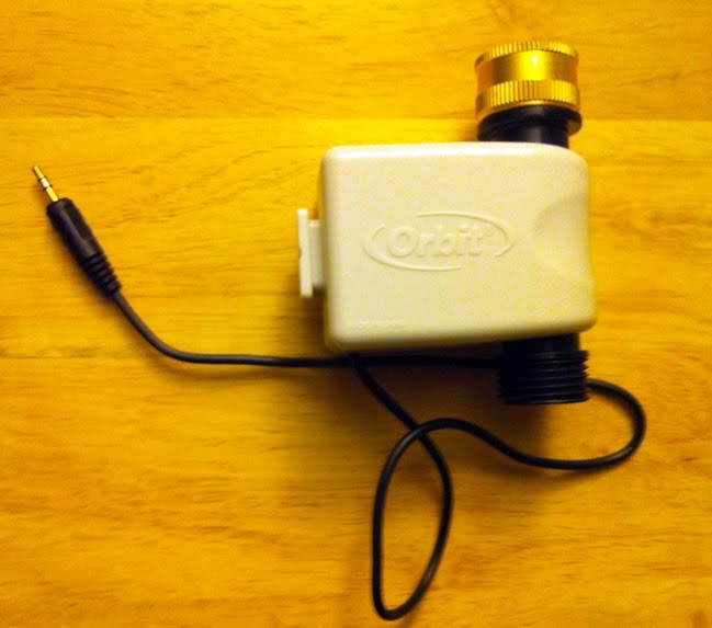
As an update to my previous post, I took a look at the Orbit 62035 valve, which works with the older Orbit’s yard watering system 62032. This valve is white colored, and has a standard 3-pin 3.5mm stereo audio plug.
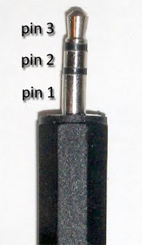 To figure out how to control the valve, my initial guess is that the valve contains two coils, one opens the solenoid and one closes it. To verify this, I measured the resistance between the 3 pins of the plug. It turns out that pin 1 and 2 have a 4.5 ohm resistance, while pin 1 and 3 have a 0.9 ohm resistance. The 4.5 ohm resistance is reasonable, as it’s roughly the same with the Orbit 91592 valve that I used previously. But the 0.9 ohm resistance is strange — it clearly indicates a coil but the resistance seems too lower.
Having no other reference, I went ahead to apply voltage on the pins to see what would happen. Interestingly, applying +24v on pin 1 and 2 successfully opens the valve, but doing the same on pin 1 and 3 fails to close the valve. I tried everything I could to figure out what went wrong, but nothing came up. Out of luck, I decided to buy the full kit (62032) and reverse engineer the control unit a little bit. When I opened the control unit, I found that the entire circuit board is covered by a thick layer of water-resistant paste. This didn’t look good. However, I did notice several big resistors, each reading about 3.9 ohm. The size of the resistors seems to suggest that they are rated at 2W.
Given this finding, my suspicion is that applying +24v directly across pin 1 and 3 discharges the voltage too quickly, thus cannot close the solenoid properly. In fact, given the 0.9 ohm resistance, a momentary current of 26 Amp is produced, which sounded quite scary. Adding a 3.9 ohm resistor is probably used to limit the current, slowing down the voltage discharge. This actually helps to build the electromagnetic field in the solenoid, allowing it to close properly. The idea turns out to work like a breeze: I connected a 3.9 ohm resistor between pin 3 and ground, and this time the valve nicely closed. At this point, I’m pretty sure I’ve figured out how it works.
You might wonder what the differences are between this valve with the Orbit 91592 valve. Here are my two cents:
Pros:
– 3.5mm stereo audio jack makes it easy to connect (in comparison, the 91592 valve requires custom connector)
– Pin 1 can remain connected to +24v, while grounding pin 2 or 3 is used to control the opening/closing of the valve. This simplifies the circuit design a lot. In fact, only two low-side drivers are needed to ground pin 2 or 3, which is much simper than h-bridge driver required by the 91592 valve.
Cons:
– Seems to be of its own kind on the market (my impression is that this is a discontinued product). Most other latching solenoids available on the market are similar to the 91592 valve. Fortunately Walmart still carries this product currently, but I don’t know how long it will last.
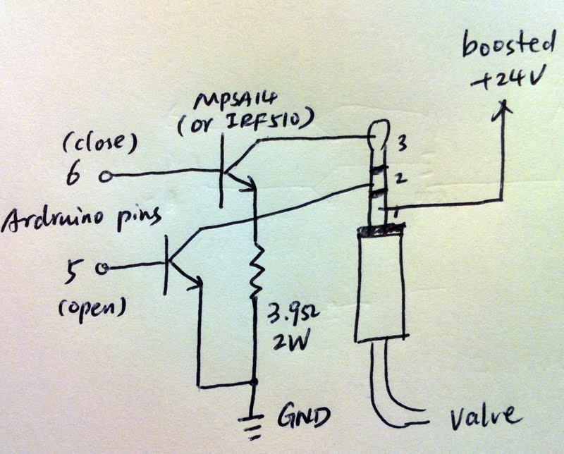
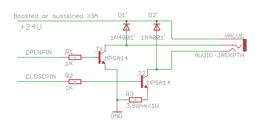
Below is a sketched schematic when using this valve to replace the 91592 valve. As you can see, the circuit is much simpler than before. The driver can use either a darlington transistor (such as MPSA14), or an N-type MOSFET (such as IRF510).