OpenSprinkler Pi Laser Cut Enclosure

For a long time, OpenSprinkler Pi (OSPi) has been using the OpenSprinkler injection molded enclosure. While this has worked fine, the enclosure is not particularly designed for OSPi, leaving some cutouts not aligned with Raspberry Pi. Recently I have started learning to design enclosures using laser cut acrylic pieces. This is a great way to design fully customized enclosures for circuits. Today the first batch of laser cut enclosures for OSPi has arrived, and we will be shipping these with OSPi kit right away.

Here is a picture of the enclosure pieces and screw bag:
img_1262

And here is a picture of the enclosure after it’s fully assembled. After removing all the protective papers from the acrylic pieces, it produces a fully transparent look of OSPi, which is pretty cool.
img_1261

It’s not necessary to remove all the protective papers. I would recommend leaving the papers on except the top panel. This way it gives a kind of wooden texture of the enclosure, and adds more protection to the enclosure.

Below is an instructional video that walks you through the assembly steps:

I will make a separate post shortly that explains how to automate the design of such laser cut enclosures.

Raspberry Pi Zero Works with OpenSprinkler Pi

My fortune cookie last night said I have recently left many things undone, and at this rate I may never get them done. Quite alarming indeed. One of the things I haven’t done well recently is regular posting on this blog. So I’ve decided that before the year ends, I have to remedy this by writing a couple of new posts.

The first order of business today is Raspberry Pi Zero. I am sure many of you have heard of it, which is the latest new comer in the Raspberry Pi family, and it has a jaw-dropping price of $5. Five dollars for a tiny computer that runs a full Linux system, how amazing is that! Well, since announced, it’s in such high demand that it went out of stock at most online stores. I’ve been waiting to get my hands on one for a while. A few days ago I was visiting friends in Long Island, New York and discovered that surprisingly I can get the Zero from Micro Center retail stores. So I went and purchased one in their Westbury store. It took me a while to find it in a locked cabinet, and apparently it’s limited to one board per customer. It’s such an anomaly, because normally things in high demand and so difficult to get would be very pricey, but this is only $5!

IMG_3369IMG_3370

The main reason for me to get one is to verify if it works well with OpenSprinkler Pi, as several customers have asked me. The answer is yes, as the video demo below shows. But before you decide to dive in, you should be aware of the hidden costs, which can quickly add up. First, to reduce cost the Zero does not have the 2×20 pin headers pre-soldered, and it doesn’t have a standard size USB connector. This means in order to use it with OpenSprinkler Pi, you need to hand solder the pin headers; and in order to connect it to a USB WiFi dongle, you need a microUSB to USB adapter, which is commonly known as the OTG (USB On-the-Go) adapter. If you are not willing to go through the hassle, you’d be better off staying with Raspberry Pi A+, which is only $20.

Here is a display of three Raspberry Pi’s: version 2 model B, A+, and Zero.
IMG_3371

The OTG adapter I ordered hasn’t arrived yet, so I decided to make one myself. It’s quite easy: just cut the connectors from an existing microUSB cable and USB extension cable (which has a USB A female connector), strip them, solder the four internal wires with matching colors, and use some hot glue and electric tape to fix everything in place. I then burned a new microSD card (with the latest Raspbian image) and installed the OpenSprinkler firmware. Plug it into the OpenSprinkler Pi circuit board, and insert 24VAC power supply: Voilà, it boots up in under a minute and I can start turning on and off sprinkler valves right away. There you go, it’s verified! For those who want to see real actions, check out the Youtube video below.

IMG_3372IMG_3373

Currently the OpenSprinkler Pi circuit board doesn’t have screw holes that match those on the Zero. The consequence is that the Zero won’t have much physical support other than the 2×20 pin header, which is pretty tight and does provide reasonable support. I will have to modify the board design to incorporate the screw holes. I am half hoping that the Raspberry Pi foundation would release a new version of Zero with the pin headers pre-soldered and a standard size USB connector. Not sure if this will ever happen, but we will see!

OpenSprinkler Recent News and Updates (Feb 2015)

Hey, it’s March already, that means spring will be here soon! Amid an unusually cold winter and freezing weather this winter in New England, we’re finally starting to see some warm winter days. No more snow please, we’ve had enough 🙂

Ars Technica
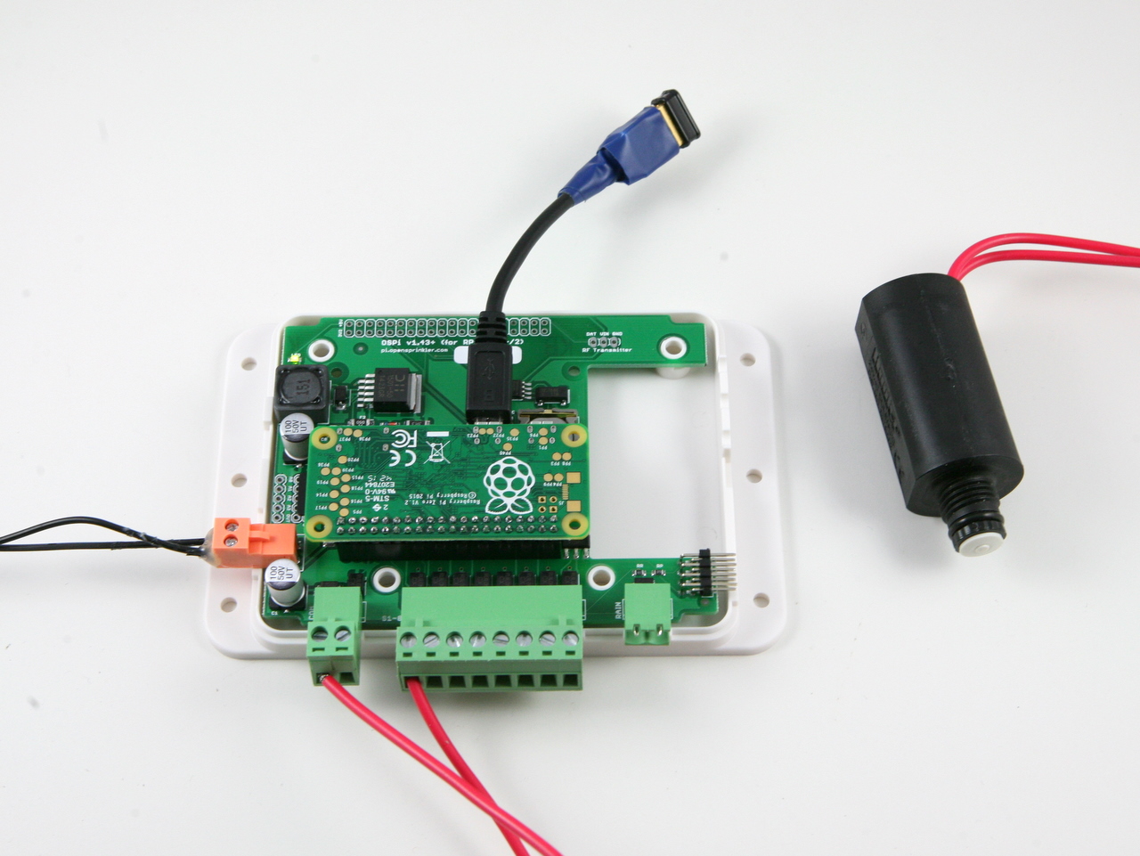
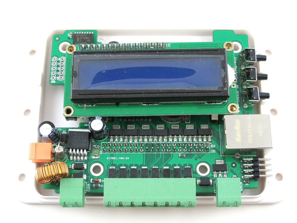
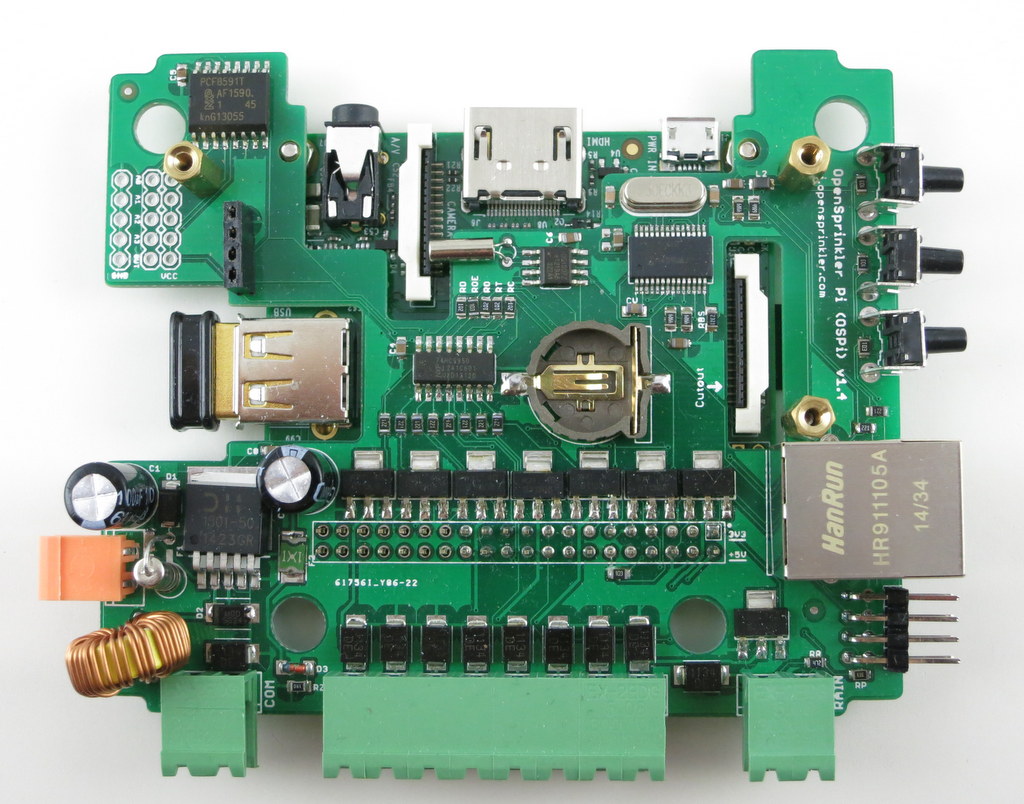
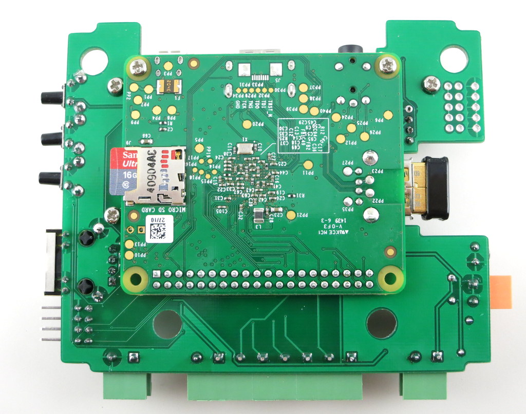
This post is to give you some recent updates on OpenSprinkler and upcoming plans. First of all, OpenSprinkler Pi got blogged by Ars Technica, which is super cool. It’s really a fun article to read. That caused a huge spike of orders, but we managed. I only wish that Cyrus Farivar, the author, had talked about the microcontorller-based OpenSprinkler as well, because appearance-wise it looks more elegant.

Unified Firmware 2.1.3

Next, we just released the first version of the Unified OpenSprinkler Firmware, numbered 2.1.3. The biggest benefit of this firmware is that it’s cross-platform — it can compile and run on all OpenSprinkler hardware platforms, including the standard OpenSprinkler (OS), OpenSprinkler Pi (OSPi), and OpenSprinkler Beagle (OSBo). The cross-platform idea was inspired by Rich Zimmerman’s sprinklers_pi program. The purpose is to make a fully consistent firmware for OS, OSPi and OSBo, so that the same firmware and same features are available on all of them.

Technically, the unified firmware is written in C++. It’s done this way to share the code between OS, OSPi and OSBo as much as possible. The major differences are that on OS, all non-volatile memory data (such as options, program settings) are stored in EEPROM, while for OSPi/OSBO, these are stored in a local file, which simulates EEPROM. Also, OSPi/OSBo uses the standard socket to handle Ethernet communication, while OS uses an Arduino EtherCard library. Other than these, the code is largely shared between them, making it easy to extend in the future. Folks may find C++ based programs less friendly to modify than Dan’s Python-based interval_program. However, as I said, the point is to make the three platforms maximally compatible, so that any new features introduced in OS will be simultaneously available to OSPi and OSBo.

The main added new feature of this firmware is the support of using sunrise/sunset times in program settings. Specifically, the program’s first start time (and any of the additional start times) can be defined using sunrise/sunset time +/- an offset (in steps of minutes) up to 4 hours. The program preview will also take into account the sunrise/sunset time of a specific day. Another change is the support for MD5 hashed password, which attempts to address the previous plain-text password to some extent. For the security-minded, I admit that this is far from sufficient, but better than before.

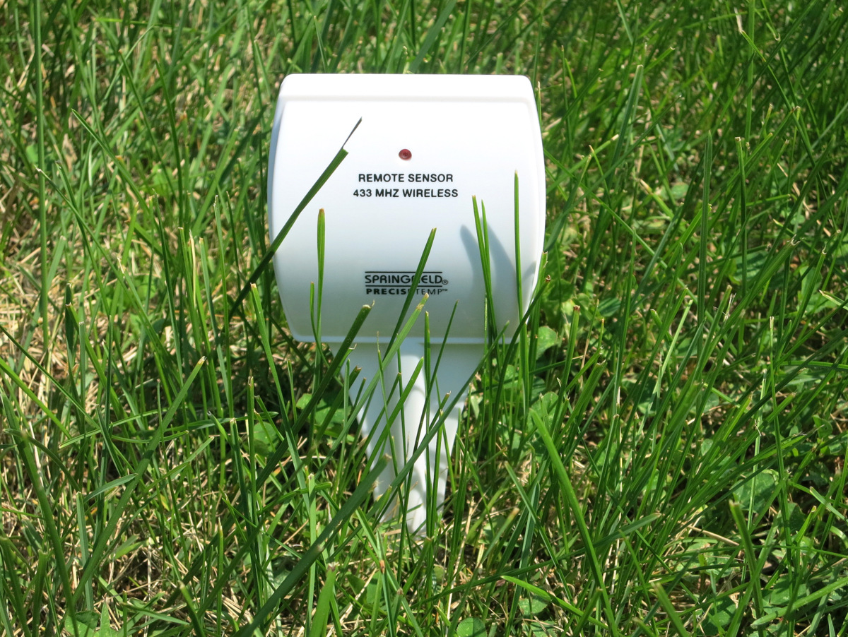
For OSPi/OSBo, all features currently implemented on the OS, such as individual station water time, Zimmerman’s weather-based water adjustment, and support for radio frequency stations, are also immediately available for OSPi/OSBo.

Details on this firmware and how to upgrade OS/OSPi/OSBo to use this firmware can be found in this forum post.

Upcoming Plans
There are quite a few things on our todo list. The top items include:

  • Getting OpenSprinkler certified by the EPA WaterSense program (which requires ET-based water time calculation).
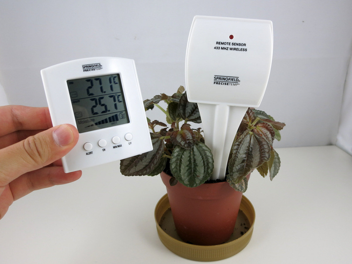
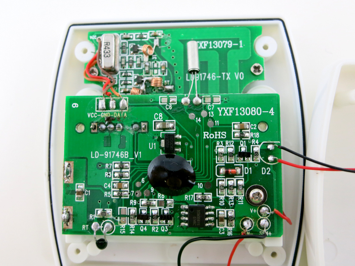
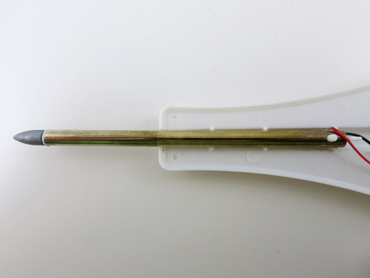
  • Support for soil moisture sensor and flow sense (at least flow estimation).
  • Improve the scheduling algorithm to better handle overlapping schedules using a queue.
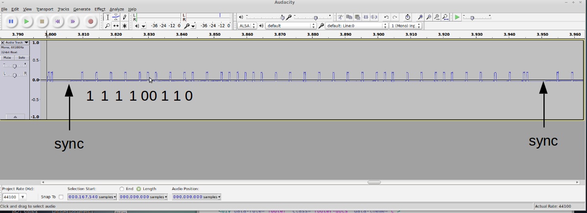
  • Adding firmware support for using sensors (either digital or analog) to trigger sprinkler events.
  • Adding cloud-support (long term goal).

Some of these are purely software, but some will entail hardware changes. For example, for cloud-support, we’ve come to the conclusion that it will require an upgraded microcontroller due to the resource limitations of the current hardware. So the cloud support will likely not happen until OpenSprinkler 3.0 comes into place. It seems that adopting ATmega1284 is the most straightforward solution — it’s totally pin compatible with the current ATmega644, but doubles the flash memory space and quadruples RAM size. If you have suggestions about desired hardware changes, please feel free to let me know. This is the time that your opinions will be factored into the future of OpenSprinkler 🙂

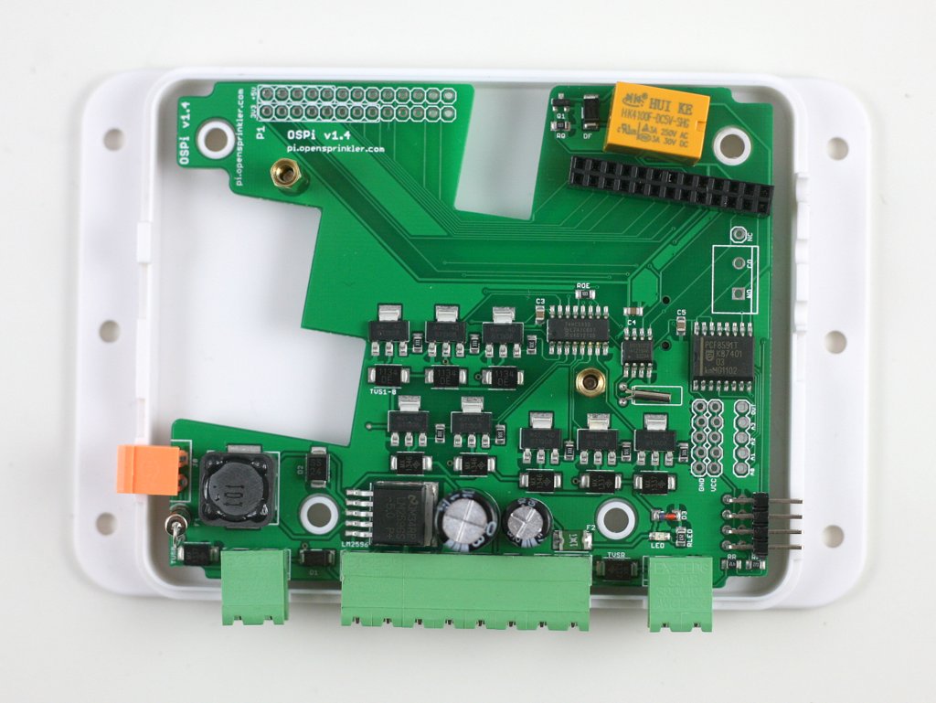
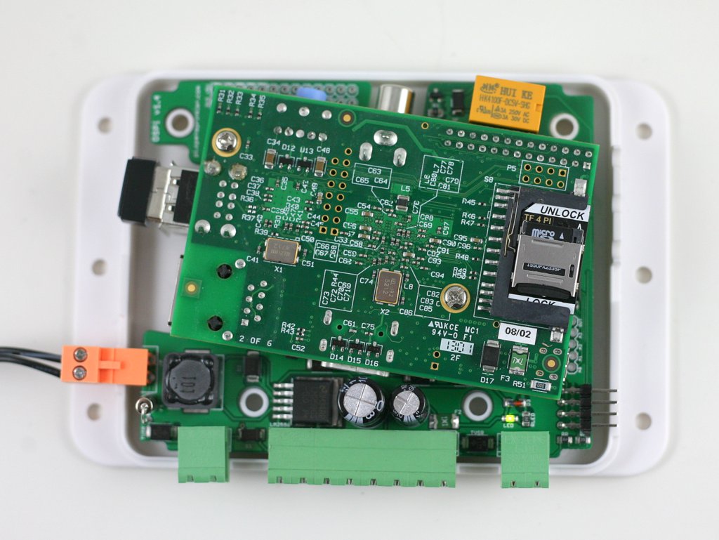
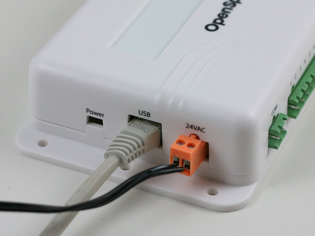
Besides the additional new features, we are also planning to remove some features which are rarely used. One immediate plan is to remove the built-in relay, which seems not very useful, only to add manufacturing cost. The original idea of including a built-in relay is to use it for general-purpose switching, such as garage doors, landscape lighting etc. However, there is no cutout dedicated to the relay wires, so it requires some modification to the enclosure. Also, now that we have support for Radio Frequency (RF) stations, the need for build-in relay is even lower. Alternatively, you can use an external 24V AC relay, which I blogged about previously. At any rate, it seems wise to retire the built-in relay.

Retiring OpenSprinkler DIY and OSPi Standard Version
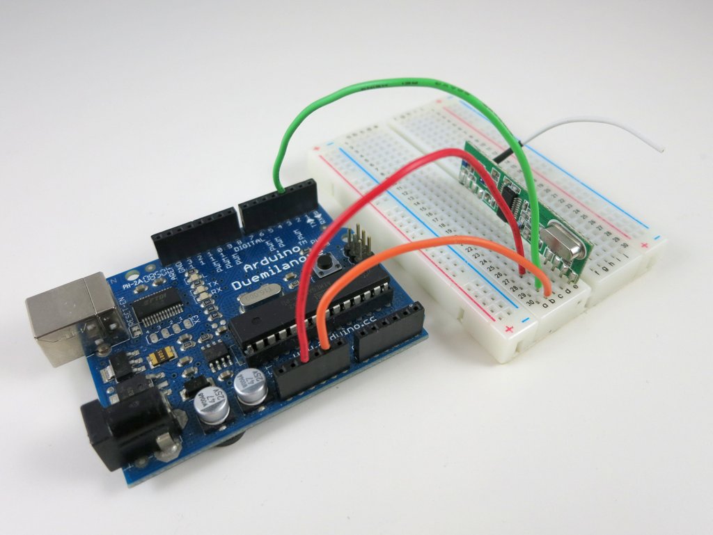
To prioritize our business, we have decided to permanently discontinue OpenSprinkler DIY kit and OSPi Standard version. We will no longer stock these kits. I know that OpenSprinkler DIY kit has been a fun product for many makers and Arduino lovers. But the maintenance cost is also pretty high — even though we do not officially provide technical support for DIY kits, in practice we still help users a lot in fixing their soldering mistakes and diagnosing issues. This has taken too much overhead, and because of this reason, we will retire the DIY kit.

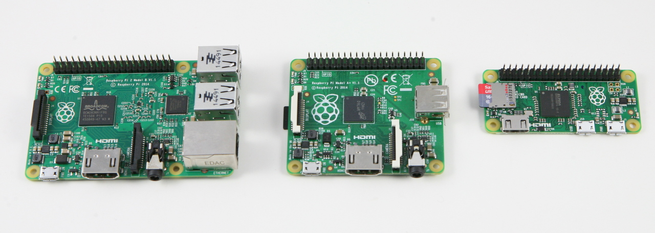
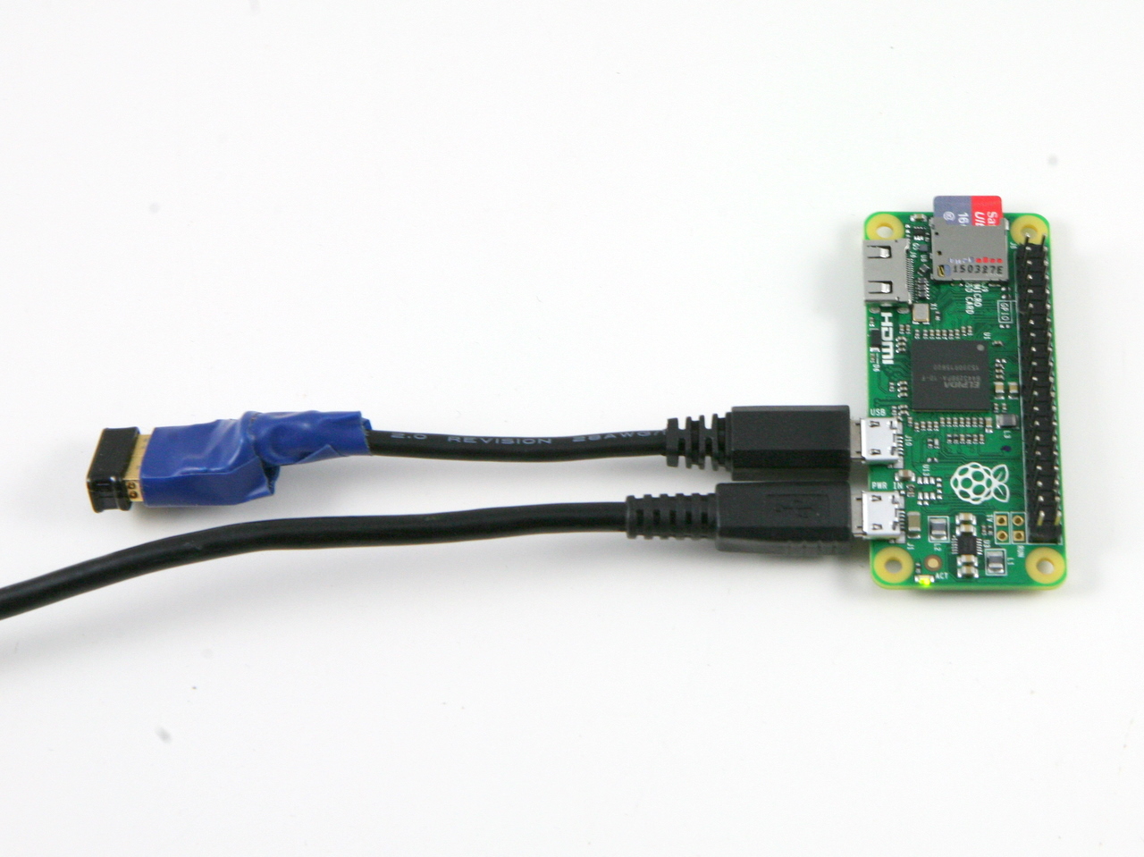
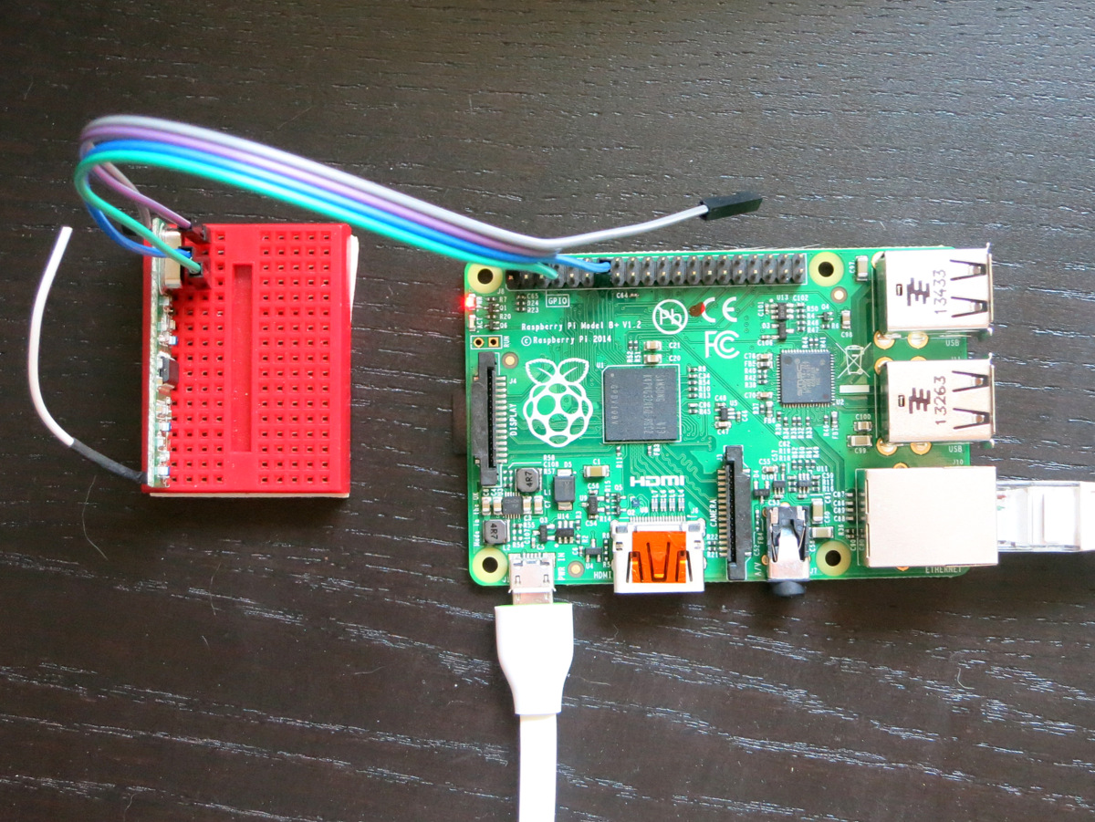
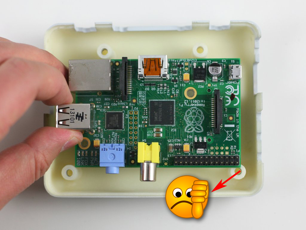
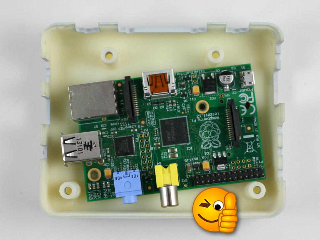
As for the OSPi Standard version — it will also be retired soon in favor of the Plus version. Most of Raspberry Pi’s new products, including A+/B+/2 use the same form factor, which is not compatible with the original A/B. The standard version is still compatible if you own a RPi 1 model A/B. But we are looking into the future, and expect the orders of the standard version to drop significantly in the upcoming season.

DC Powered OpenSprinkler
I’ve received several requests to make an OpenSprinkler variant for DC solenoids. Within the US, most sprinkler solenoids are still AC powered. But for International users, it can be painful and confusing to find a AC power source, especially since AC adapters are not regulated (i.e. you can’t plug in a 110VAC adapter to 220VAC socket). In contrast, DC adapters and solenoids are sometimes more common and cheaper to source, and DC adapters are usually regulated and universal.

In a previous blog post, entitled Understand 24V AC Sprinkler Solenoids, I analyzed the electric specs of a typical sprinkler solenoid. One interesting discovery there is that it’s totally possible to drive a 24V AC sprinkler solenoid using DC voltage. The trick is that it needs a high momentary voltage to activate, but once activated, it can remain open with a relatively low voltage (some where around 6~8 VDC). This means a DC powered OpenSprinkler not only works for DC solenoids, but can work for a typical 24V AC solenoid as well. In fact, combining this with the H-bridges that OpenSprinkler Bee uses, it’s even possible to use the same hardware to drive DC Latching solenoids as well! Perhaps I can call this the Unified OpenSprinkler Hardware design 🙂

Inspired by this idea, I am actually working on a DC version of OpenSprinkler. Besides the benefits to International users, another benefit of a DC design is that this makes it easy to add a current sensing circuit to monitor each station, and detect potential solenoid shorting / damage etc.

Work in Progress: OpenSprinkler Pi (OSPi) A+ will Finally Close the Gap

When I first had the idea to design OpenSprinkler Pi (OSPi), a secret motivation was that one day I figured out how to fit Raspberry Pi into the existing OpenSprinkler enclosure. Yes, it sounds silly, and you can laugh at it; but if you understand how much it costs to make an injection molded enclosure, and how difficult it is to predict the market and demand, you will see why I wasn’t quite ready to invest on a whole new enclosure for OSPi.

The experience last year has proven that OSPi is quite popular. I really enjoyed seeing the amount of community development on it, primarily due to the low cost of RPi and the flexibility in programming the RPi. We’ve also seen continued evolution of RPi, from the early A and B models to B+ and more recently A+. On the plus side, it’s exciting to see that RPi continues to become smaller and cheaper. The A+ version is now 25% smaller and you can get one for just $20. On the other hand, I am sure the different versions created some challenges in re-designing products powered by RPi. Because each version has different peripheral elements, size, screw hole locations, it’s quite difficult to design one board that fits all versions.

So in a way, I felt lucky that I wasn’t too hasty to invest on a dedicated enclosure for OSPi, because whatever I would have designed would probably not fit A+ in the end. But the lack of a dedicated enclosure has always been the major confusion about OSPi: from time to time I receive questions about why the cutouts on the enclosure do not match RPi, and then I have to explain. It’s not ideal.

Here comes the good news: with RPi A+, it looks like I may be able to ‘close the gap’ finally — that the injection-molded OpenSprinkler enclosure will finally fit OSPi, without confusing mis-alignment of the cutouts, and with buttons and LCD, just like the microcontroller-based OpenSprinkler!

Here are some pictures to show you the proof-of-concept:
IMG_0582IMG_0583
IMG_0584IMG_0585

Mounting RPi. The most dramatic change is that RPi A+ will be mounted at the back of the OSPi circuit board. This is necessary to make space for the LCD (explained below). This may look surprising, but because A+ is quite flat, there is sufficient space at the back of OSPI to fit it, except HDMI, USB, and other peripheral connectors, which I’ve made cutouts for.

There is no secret that I’ve always enjoyed solving the ‘how to fit RPi into the OpenSprinkler case’ problem. It’s like a geometry puzzle for me. Often constraints push me to think of new solutions. So bear with the nerdy side of me 🙂

LCD. Next, for the LCD I am using I2C LCD — it’s the standard 1602 LCD with a I2C module at the back. This turns out to be very important, because I2C LCD needs only 4 pins in total (VCC, GND, SDA, SCL), significantly reducing the pin requirement and saving space. You can buy these with pre-soldered I2C modules, at very small added cost.

Buttons. There is also space to fit 3 push-buttons on the right-hand side of the circuit board. The physical buttons can be quite useful for triggering events or performing manual sprinkler control.

Ethernet. Lastly, I don’t want to waste the cutout for Ethernet jack, so I even added a ENC28J60 Ethernet controller. This is a useful add-on for RPi A+, which doesn’t come with an Ethernet jack itself. It took me quite while to figure out how to re-compile the RPi kernel to support this Ethernet controller. Don’t expect it to be very fast, but it comes handy if you really need wired Ethernet connection. Most people will still prefer the WiFi dongle.

IMG_0586

One of the biggest drawback of this design is that RPi A+ will now be permanently soldered onto OSPi, because there is simply no space in height to put pin headers. This is not ideal but I can’t think of a better choice. The other potential issue is the heat dissipation of RPi — although there is some space between RPi, OSPi, and the enclosure bottom, it can become an issue during hot summer days. There is some space on the board to make vent holes, so I will see what I can do.

To summarize, this is a proof-of-concept design for OSPi A+ — it will finally make the injection-molded enclosure work perfectly for OSPi. Because this is a very early prototype, don’t expect it to be available anytime soon, although I do hope to make it ready by summer time this year.

Feedback, comments, and suggestions are welcome. Thanks!

Verified: OpenSprinkler Pi (OSPi) 1.4 works with Raspberry Pi A+

As you’ve probably heard: the Raspberry Pi Foundation recently released RPi A+, which is the first RPi that’s smaller in size than any other RPi. It is essentially a B+ with less memory (256 MB vs. 512 MB), one USB port (instead of four), and a compact form factor (65mm vs. 85mm). Not only is it smaller, but it’s lighter, consumes less power, and best of all, it’s cheaper — only $20!

There is a famous Chinese saying: “A sparrow may be small but it has all the vital organs”. This is exactly what I feel about RPi A+. Although it’s almost 25% smaller than any other RPi, it retains all the essential features. Similar to B+, it has a microSD card slot, and hybrid audio / composite video port. This helps reduce the overall size of the assembly. It doesn’t have a built-in Ethernet controller and connector (which contributed to the lower price tag), but most people will likely use a USB WiFi dongle anyways so it’s not a big loss. What’s clever about its design is that it’s pin compatible with B+ — in fact it’s basically B+ with 20mm chopped off from the right edge. All the connectors, pin headers, screw hole locations are exactly the same as B+. This means any shield / extension board that works for B+ is likely to work for A+ with no modification.

Such is the case with OpenSprinkler Pi (OSPi) — the B+ version works perfectly fine for A+. Below are two pictures showing OSPi v1.4 (B+ version) with A+ installed. As you can see, it leaves extra space on the right-hand side to fit additional components.

IMG_0484IMG_0485

As you may have guessed: given the extra space, the first components I will consider adding are three pushbuttons. This makes a lot of sense. So far OSPi has been using the same enclosure as the microcontroller-based OpenSprinkler. Because the enclosure is unfortunately not tailored to OSPi, there are several cutouts left unused, such as the pushbutton cutouts, Ethernet, LCD, USB, and power switch. With the extra space on the right, pushbuttons are the easiest to add back. Ethernet controller and connector can also be added, although as I said above I am not sure how useful they are, since most people would probably prefer using USB WiFi dongle.

LCD is another popular feature that has been requested. This is a bit tricky to add because there is simply not enough space in height to fit a standard 1602 LCD like the microcontroller-based OpenSprinkler. However, I’ve got a wild idea that I think is going to work. If this is feasible, then OSPi will truly look just like the microcontroller-based OpenSprinkler. I will post an update as soon as my idea is verified. Stay tuned!

Reverse Engineer a Cheap Wireless Soil Moisture Sensor

At the Maker Faire this year I got lots of questions about soil moisture sensors, which I knew little about. So I started seriously researching the subject. I found a few different soil sensors, learned about their principles, and also learned about how to make my own. In this blog post, I will talk about a cheap wireless soil moisture sensor I found on Amazon.com for about $10, and how to use an Arduino or Raspberry Pi to decode the signal from the sensor, so you can use it directly in your own garden projects.

IMG_0183

What is this?
A soil moisture sensor (or meter) measures the water content in soil. With it, you can easily tell when the soil needs more water or when it’s over-watered. The simplest soil sensor doesn’t even need battery. For example, this Rapitest Soil Meter, which I bought a few years ago, consists of simply a probe and a volt meter panel. The way it works is by using the Galvanic cell principle — essentially how a lemon battery or potato battery works. The probe is made of two electrodes of different metals. In the left picture below, the tip (dark silver color) is made of one type of metal (likely zinc), and the rest of the probe is made of another type of metal (likely copper, steel, or aluminum). When the probe is inserted into soil, it generates a small amount of voltage (typically a few hundred milli-volts to a couple of volts). The more water in the soil, the higher the generated voltage. This meter is pretty easy to use manually; but to automate the reading you need a microcontroller to read the value.

IMG_0180IMG_0182

Resistive Soil Moisture Sensor
Another type of simple soil sensor is a resistive sensor (picture on the right above). It’s made of two exposed electrodes, and uses the fact that the more water the soil contains, the lower the resistance between the two electrodes. The resistance can be measured using a simple voltage dividier and an analog pin. While it’s very simple to construct, resistive sensors are not extremely reliable, because the exposed electrodes can degrade and get oxidized over time.

Capacitive Soil Moisture Sensor
Capativie soil sensors are also made of two electrodes, but insulated (i.e. not exposed). The two electrodes, together with the soil as a dielectric material, form a capacitor. The higher the water content, the higher the capacitance. So by measuring the capacitance, we can infer the water content in soil. There are many ways to measure capacitance, for example, by using the capacitor’s reactance to form a voltage divider, similar to the resistor counterpart. Another way is to create an RC oscillator where the frequency is determined by the capacitance. By counting the oscillation frequency, we can calculate the capacitance. You can also measure the capacitance by charging the capacitor and detecting the charge time. The faster it charges, the smaller the capacitance, and vice versa. The Chirp (picture below), which is an open-source capacitive soil sensor, works by sending a square wave to the RC filter, and detecting the peak voltage. The higher the capacitance, the lower the peak voltage. Capacitive sensors are not too difficult to make, and are more reliable than resistive ones, so they are quite popular.

chirp

More Complex Soil Sensors
There are other, more complex soil sensors, such as Frequency Domain Reflectometry (FDR), Time Domain Reflectometry (TDR), and neutron sensors. These are more accurate but also will cost a fortunate to make.

Wireless Soil Moisture Sensor
Because soil sensor is usually left outdoors, it’s ideal to have it transmit signals wirelessly. In addition, because soil moisture can vary from spot to spot, it’s a probably good idea to use multiple sensors distributed at different locations to get a good average reading. Wireless would make it more convenient to set up multiple sensors.

Recently I found this 433MHz wireless soil sensor from Amazon, for only $10, very cheap. It comes with a transmitter unit and a receiver display unit. The transmitter unit has a soil probe. The receiver unit has a LCD — it displays soil moisture level (10 bars) and additionally indoor / outdoor temperature. Let me open up the transmitter to see what’s inside:

IMG_0177IMG_0178IMG_0179IMG_0181

There is a soil probe, a 433MHz transmitter, a microcontroller at the center, a thermistor, and a SGM358 op-amp. Pretty straightforward. The soil probe looks quite similar to the battery-free soil meter probe that I mentioned above. So I am pretty sure this is not a resistive or capacitive probe, but rather a Galvanic probe. Again, the way it works is by outputting a variable voltage depending on the water content in soil. By checking the PCB traces, it looks like the op-amp is configured as a voltage follower, which allows the microcontroller to reliably read the voltage generated by the Galvanic probe.

Now we understand the basic principle of the sensor, let’s take a look at the RF signal from the sensor. I’ve done quite a few similar experiments before, so I will just follow the same procedure as described in this post.

Raw Waveform. To begin, I use a RF sniffing circuit to capture a raw waveform, which looks like this:

soil_waveform

Encoding. Each transmission consists of 8 repetitions. The above shows one repetition: it starts with a sync signal (9000us low); a logic 1 is a impulse (475us) high followed by a 4000us low; a logic 0 is the same impulse high followed by a 2000us low. So the above signal translates to:

11110011 01100000 11111111 00111001 1111

The signal encodes both temperature and soil humidity values. By varying temperature and soil moisture, and observing how the signals change, it’s pretty easy to figure out that the 12 bits colored blue correspond to temperature (10 times Celcius), and the 8 bits colored red corespond to the soil moisture value. The first 12 bits are device signature, which is quite typical in this type of wireless sensors; the last four bits are unclear, but likely some sort of parity checking bits for the preceding four bytes). So the above signal translates to 25.5°C and a soil moisture value of 57.

The display unit shows soil moisture level in 10 bars — 1 to 3 bars are classifed as ‘dry’, 4 to 7 bars are classified as ‘damp’, and above 7 bars are classified as ‘wet’. How does this translate to the soil moisture value? Well empirically (from the data I observed) the dry-damp boundary is around 60, and damp-wet boundary is around 100.

Arduino Program. I next wrote an Arduino program to listen to the sensor and display the soil moisture value and temperature to the serial monitor. For this you will need a 433MHz receiver, and the program below assumes the receiver’s data pin is connected to Arduino digital pin 3. Because the encoding scheme is very similar to a wireless temperature sensor that I’ve analyzed before, I took that program and made very minimal changes and it worked instantly.

IMG_0051soil_display_arduino

Raspberry Pi Program. By using the wiringPi library, the Arduino code can be easily adapted to Raspberry Pi. The following program uses wiringPi GPIO 2 (P1.13) for data pin.

IMG_0185IMG_0184

I haven’t done much tests about the transmission range. I’ve put the sensor at various locations on my lawn, and I’ve had no problem receiving signals inside the house. But my lawn is only a quarter acre in size, so it’s not a great test case.

One thing I really liked about using off-the-shelf sensors is that they are cheap and have ready-made waterproof casing. That combined with an Arduino or RPi can enable a lot of home automation projects at low cost.

OpenSprinkler Pi (OSPi) Manufactured Locally at WAi

Back in April, I blogged about WAi (Worthington Assembly Inc.), a circuit assembly company located only 15 minutes away from where I live. They’ve got great reputation in the maker community, and have helped projects such as Tessel, RGB-123 LED matrices to take off. I am glad to announce that we’ve now partnered with WAi to manufacture OpenSprinkler Pi (OSPi), and the first batch of 200 boards just came out from a late-evening production yesterday. Check out these awesome videos Chris Denney took during the production:

Full-speed version

Slow-motion version

Some static pictures (taken with an outdated phone, sorry about the quality!). Picture captions: 1) tapes loaded onto pick-and-place machine; 2) first board came out of the reflow oven; 3) first board after AOI inspection; 4) me holding a stack of 25 panels.
0612141917a0612142026

06121420390612142235

Compared to manufacturing in China, using a local facility has the unbeatable advantage of quick turn-around time. The cost may be higher than made in China, but for an open-source hardware business like us, it’s critical to remain agile and be quick about making changes. I’ve been there — waiting for months for an order to ship from China, which was painful and stressful. By the time the shipment arrived, I already wanted to move on to the next version. With WAi, we may have found just the perfect solution for our need, and this is supporting local manufacturing too, win-win! 🙂

Funky Design of the New OpenSprinkler Pi (OSPi) v1.4

Curious what the next version of OpenSprinkler Pi (OSPi) is going to look like? Here is a sneakpeak preview of version 1.4:

IMG_3118IMG_3125

Wait a minute, what is this strange looking board?! And the Pi is installed at an angle? What’s happening here? Well, the new design is all centered around one simple goal: to fit OSPi and RPi into the existing OpenSprinkler injection-molded enclosure. There are many good reasons to do so. The first is cost reduction: the current OSPi uses the Serpac WM032 enclosure with custom cutouts. This is quite expensive to make. On the other hand, the microcontroller-based OpenSprinkler already has an injection-molded enclosure (and I paid a good amount of money for the mold!), so it makes sense to consolidate the design to use the same enclosure. This will bring down the cost quite a bit. Using the same enclosure also gives both products a consistent look. In fact, in the near future OpenSprinkler Beagle will also adopt the same enclosure, and hence all three will have the same exterior look.

Design Story

The ‘why’ part is easy to explain. But the ‘how’ part proves to a non-trivial engineering challenge. When I was first fiddling with the idea I didn’t think it was at all possible. After all, the injection-molded enclosure was made before OSPi came into place, naturally it was not designed with RPi in mind. It turns out that, due to the positions of the support pillars, the enclosure is just a little bit too narrow to fit RPi at a straight angle. Ouch! But after staring at it for a while like a geometric puzzle, I was delighted to find out that if you rotate RPi by 3 to 4 degrees, it fits perfectly! This gave me inspiration to further develop the idea. It also explains why the Pi has to be installed at an angle, as the picture at the top shows.

IMG_3132IMG_3133

In fact, by carefully positioning the Pi, the Ethernet cable can also fit, albeit through the USB cutout instead of the RJ45 cutout. It’s a bit tricky to figure out the position precisely, but I am glad that after two rounds of prototypes I finally got it right 🙂

IMG_3129IMG_3130

Of course since OSPi doesn’t have buttons and LCD, some of the cutouts are useless. I am not completely sure what to do with the LCD cutout. If I leave it alone, it looks quite ugly (see picture on the left below). So my temporary solution is to just put a sticky label at the back, thus covering the big empty hole (see picture on the right below). Eventually I think it’s best to put some graphic design here. I am undecided what to put here. It shouldn’t be the OpenSprinkler logo as the enclosure already has a printed logo. If you have suggestions, please leave them in the comments section. I would greatly appreciate it!

IMG_3127IMG_3128

Next, because the injection-molded enclosure is not high enough, I cannot continue using the current design where the Pi faces up and connects to OSPi through ribbon cables. It’s necessary to flip the Pi and plug it into OSPi facing down. This will reduce the height of the overall assembly. However, there is one additional complication: the USB, Ethernet, and composite video connectors on the Pi are all quite tall, so it’s necessary to make cutouts on the OSPi PCB to allow these connectors to sink below the board. The picture on the left below shows the back of the PCB, and you can see where the connectors go through the board.

IMG_3134IMG_3120

As the Pi is now facing down, it’s not easy to access the GPIO pins directly. Therefore I’ve mapped out all the 2×13 pins on the Pi to the pinout area, seen at the top-left corner of the PCB.

The last bit of the puzzle is the SD card. Since the enclosure has very limited space, it’s not possible to fit a full-size SD card, without making a cutout on the side. So we need a low-profile SD card. There are several options, one is this microSD to SD adapter. It’s basically a microSD card slot soldered onto a PCB shaped like an SD card but half the size. This and other similar adapters are readily available online and they work reasonably well.

IMG_3122IMG_3119

While Googling ‘low-profile SD card’, I found an surprising solution that’s dead simple. In case you don’t know this already: many full-size SD cards are actually half empty. What this means is that the useful stuff (namely the chip and connectors) only take half the space, while the other half has nothing in it! As a result, you can safely cut half of the card away, thus making a low-profile SD card without any adapter. This also has the advantage of preserving the high performance of a full-size SD card (while the microSD card is considerably slower). The downside though, is that if you ever need to insert the SD card to your computer’s SD card slot, you will have to tape the other half back, so that it extends to the original length. Otherwise it will be too short to push in and pop out.

IMG_3123IMG_3124

Anyways, this is the end of the story. I admit the new funky design feels a bit forced: it’s born out of the need to re-use the injection-molded enclosure, which wasn’t designed with OSPi in mind. But I am quite excited that I figured out all the pieces of the puzzle. Eventually I may pay a sizable chunk of money to order a new mold dedicated to OSPi, but before that happens we have to stick with the existing resources 🙂

The hardware components remain largely the same with version 1.3. The only difference is that the relay has been upgraded to a slightly bigger, 250V / 3A type. I am also considering adding a pin header for the nRF24L01 transceiver, to make it possible to communicate with our upcoming products such as OpenSprinkler Bee. Pending a few minor tweaks, things should be finalized within a month or two. Please leave your comments and suggestions, as this will be the last chance to influence the final design of 1.4. Thanks!

OpenSprinkler Pi (OSPi) Pre-Configured SD Card Image for Download


Update: information on this blog post is outdated. Please check the latest instructions in the OSPi v1.4 user manual.


Good news to OSPi users: a pre-configured SD card image is now available for download at the following url:

NOTE: OSPi v1.4 requires either a microSD card or a low-profile SD card (due to the limited space in the enclosure). A microSD card adapter for RPi is included in the kit.

The image is compressed from an existing OSPi installation that contains Dan’s interval_program, Rich’s sprinklers_pi program, Samer’s OpenSprinkler mobile app, and the Google Calendar-based scheduling program. Download it, burn it to an SD card, and pop it in to your Raspberry Pi. Then you will be ready to go right away. No more pulling your hair or banging your head against the wall (well, hopefully :))!

The process to burn the image to an SD card is the same as burning a raspbian image to SD card. If you’ve used Raspberry Pi before, you’ve probably done this already, maybe even multiple times. If not, you should check the detailed online instructions here: http://elinux.org/RPi_Easy_SD_Card_Setup

Here is a quick summary:

  • Decompress the image file to your computer.
  • Insert an SD card (4GB or above). Make sure you back up any important file on the SD card as the procedure below will overwrite the content on the SD card.
  • Depending on what operating system you use:
    • On Windows, use the Win32DiskImager software.
    • On Mac, use the ‘dd’ command in a terminal, for example: sudo dd bs=1M if=name_of_the_image_file of=/dev/partition_to_burn_to
    • On Linux, the same, use the ‘dd’ command on a terminal, for example: sudo dd bs=1M if=name_of_the_image_file of=/dev/partition_to_burn_to
    • VERY VERY IMPORTANT: make sure you have selected the correct drive name (or partition name) to burn the image to!!! If you’ve selected the wrong drive, you might end up wiping out your computer’s hard drive, and I am sure you will be back pulling your hair again!!! Double check before you press enter or click on confirm.

Once the SD card is ready, pop it in to your Raspberry Pi. Since WiFi is not configured yet, you should first connect it directly to your router using a wired Ethernet cable. Alternatively, if you are a Linux user, insert the SD card to your computer, and you directly edit the WiFi SSID and password in file /etc/network/interfaces on the SD card (not your computer!). This way when you pop it in to RPi, it will automatically connect to your WiFi network.

In your home router’s configuration page, find out the IP address assigned to the Raspberry Pi. Next, open a browser, and type in:
http://x.x.x.x
where x.x.x.x is your Raspberry Pi’s IP address. You should see a page with further instructions, such as setting up time zone, WiFi etc. If you can see this page, congratulations, you’ve succeeded!

Dan Kimberling’s interval_program is set as the default program to run on start-up. Type in the following url in a browser:
http://x.x.x.x:8080
(again, x.x.x.x is your Raspberry Pi’s IP address) and you should see the web interface of the interval_program.

The OpenSprinkler mobile app is also pre-installed to the SD card, which is available at:
http://x.x.x.x/sprinklers

You can also switch to run Rich Zimmerman’s sprinklers_pi program on start-up. To do so, ssh (or use a monitor and keyboard) to your Raspberry Pi (the system uses the default user name pi and password raspberry) and run the script in a terminal: sudo /home/pi/select_program. Once you’ve switched to the sprinklers_pi program, you can access its web interface at the same http://x.x.x.x:8080.

These have all been explained in the one-page instruction. For questions, comments, and suggestions, please post them at the Rayshobby Forum: http://rayshobby.net/phpBB3. Thanks!

4gsd

OpenSprinkler Pi (OSPi) has a New Enclosure Option

We’ve just got a new batch of enclosures for OpenSprinkler Pi (OSPi). The dimensions are the same with the transparent cover enclosures we’ve been using so far, but it’s now in solid color (light gray) and comes with a printed label on top. The picture on the left below shows the new enclosure. For comparison, the picture on the right is the current one with transparent cover.

IMG_3451ospi_header

The label makes it clear where each connector is located. Also, an additional cutout is included in the left-hand side to allow an Ethernet cable to pass through. This will be useful for anyone who wants to stick with wired connection. The pictures below show the two pieces of the enclosure and the assembly from three different sides:

IMG_3450IMG_3452

IMG_3453IMG_3454

A little bit history about this: the transparent cover was originally adopted because it’s exactly the same enclosure used for Arduino-based OpenSprinkler DIY kit. There is a good reason to share the enclosure as it saves cost of having to making a new design. Now as the OpenSprinkler DIY kit will soon step up to use the injection molded enclosure, it’s time to give OpenSprinkler Pi a dedicated ‘shirt’, so that the cutouts can be more tailored to OSPi.

Anyways, the new enclosure option is compatible with all existing versions of OSPi. If you’ve purchased an OSPi in the past and prefers the new enclosure, you can purchase it separately from the store link here. Thanks!