OpenSprinkler Software Update

The OpenSprinkler software (specifically svc_demo and vc_simple_web) have been quite outdated since October last year, and I am increasingly unhappy with the issues in them. I’ve also received several requests for added features and improved user interface. Over this weekend, I have finally pulled myself together and made some updates to these programs. Here is a list of major changes:

  • Created the OpenSprinkler Arduino library, which makes it easy for code re-use.
  • Added support for arbitrary number of stations. This is probably one of the most common features requested, and it’s now generically supported in software. This will go well with the upcoming hardware update v1.1. The main additions of v1.1 are on-board pinouts and connectors to link extension boards. Each extension board consists of just a shift register, triacs, resistor networks and terminal blocks. So this is a simple and inexpensive way to scale up to potentially a large number of stations.
  • Added a self-test mode and removed the manual schedule mode. The self-test mode can be activated by holding button B1 during startup.
  • External EEPROM now stores data in NOT format (i.e. ~value instead of value), eliminating the un-initialized EEPROM issue.
  • The new svc_button_ctrl and svc_full_schedule programs. These make use of the new OpenSprinkler library and replace the previous svc_simple_web and svc_demo programs (which are now in the archived folder).

You can get a copy of the updated programs from my GitHub download page. They are backward compatible with the previous version of OpenSprinkler, so you can feel free to give them a try on your current hardware.

In order to use the OpenSprinkler library, just copy the library folder to your Arduino’s libraries directory, and then in your main code, add:


#include<OpenSprinkler.h>
OpenSprinkler svc;
void setup() {
  svc.begin();
  svc.options_setup();
}

This will create an OpenSprinkler object called svc. Check OpenSprinkler.h in the library folder for all class member functions, and the svc_button_ctrl and svc_full_schedule for examples of writing your own code. A few simpler examples will be added to the library later.

The hardware update v1.1 will be available in a week or so. I am still finishing up some documentations, but that shouldn’t take long.

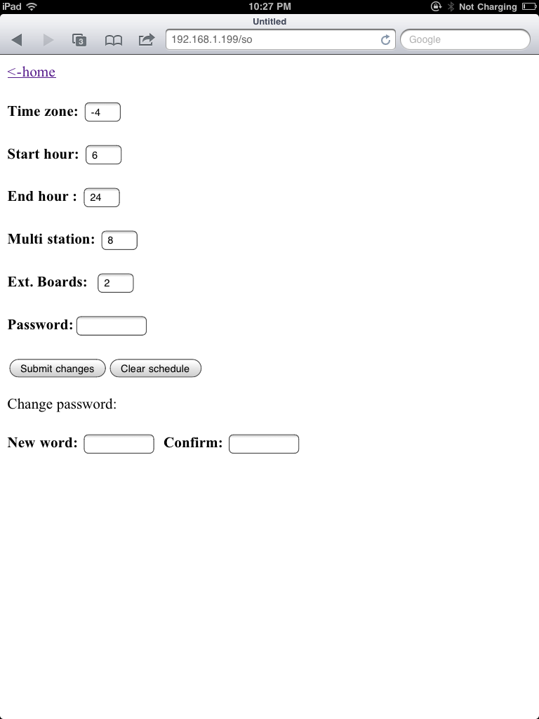
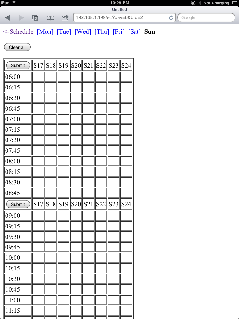
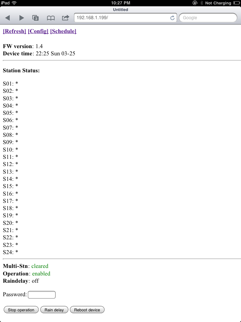
For the curious ones, here are some screen shots of webpages from the new programs. These examples show 24 stations:
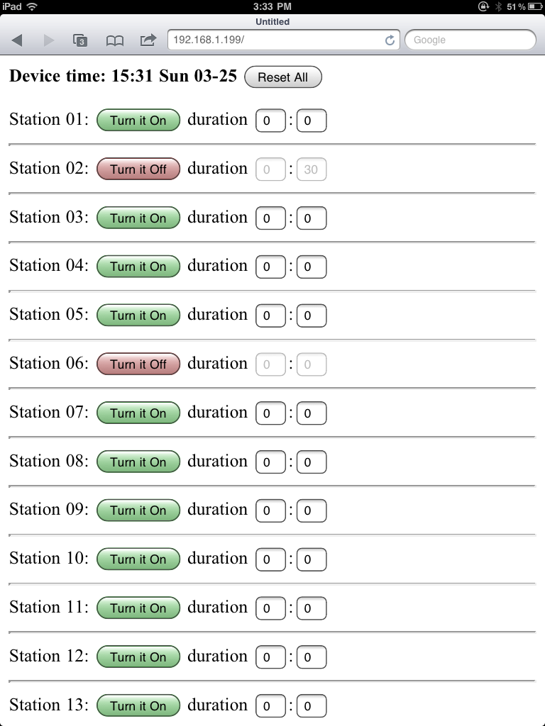
svc_button_ctrl

svc_full_schedule

Building a simple testing circuit with Pogo pins

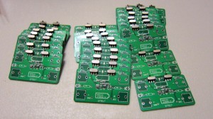
When you are making products in batches, you need a quick way to test them and make sure they function as expected. For example, three weeks ago, I sold close to 100 AASaver kits in a day, and I needed a good way to automate the testing before they are shipped out:

Well, this is what pogo pins are good for. So what is a pogo pin? It’s basically a spring-loaded pin that you can use to make a secure and temporary contact with your circuit board. It allows you to stack the testing circuit directly onto the target circuit, without any additional soldering. The picture on the right above shows an example I got from eBay. This is of model number P75-E, which is 1.02mm in diameter and 16.5mm in length, perfect for the AASaver circuit board.

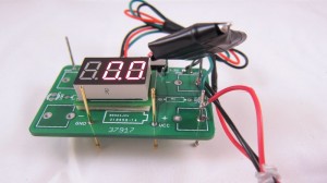
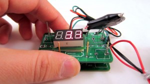
To build a tester, I need to: 1) provide input power to the target board; 2) test the output voltages (5V/3.3V); and 3) test the output current (>300mA). These can be done by making use of an existing AASaver PCB. I used a total of 5 pogo pins. Two are soldered into the battery holes to provide input power from two AA batteires; two are soldered into the Vcc and Gnd, and further connected to a mini voltage meter for testing output voltages; and one more to provide weight balance. See the pictures below.

To use the tester, I simply stack it onto a target board, and check the voltage readings. Each test can be done in less than 8-10 seconds. To test the output current, I added a 15 Ohm power resistor and a slide switch onto the testing circuit. When the switch is turned on, the power resistor is applied between Vcc and Gnd, which causes an output voltage to drop. This drop should be relatively small (<0.3V) if the target board meets the current rating (>300mA). So there you go: a simple tester for the AASaver!

AASaver Kit v1.1 is in stock

AASaver kit is now back in stock. There was a bit of delay in the shipping, but it has finally arrived! The funny thing is that the updated version (v1.1) arrived ahead of the original version, so if you place an order now, you will received the updated version, with additional features, at the same price!

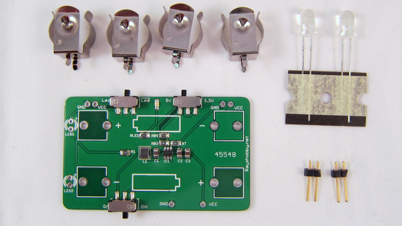
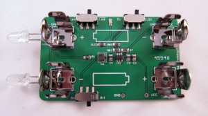
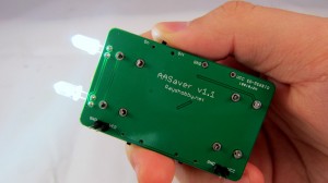
Picture of v1.1

Here is the list of changes in v1.1:

  • Moved both flash LEDs to the same side so they point to the same direction.
  • Added an on-board resistor (R1) for the flash LEDs.
  • Added a separate flash LED switch.
  • Moved the power switch to the bottom side.

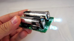
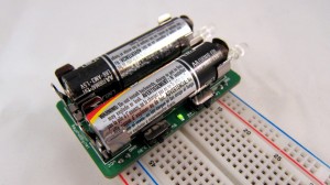
These changes were made to improve the usability. For example, the separate LED switch allows you to use it simultaneously as a breadboard power supply and flashlight (previously it was either one or the other). Also, the two LEDs now point to the same direction, so it can function better as flashlights.

The kit is available in my hobby shop. As I said, if you place an order now, you will get the updated v1.1 at the same price, until it runs out.