Introducing OpenSprinkler Bee 2.0 — a WiFi-enabled Universal Sprinkler Controller

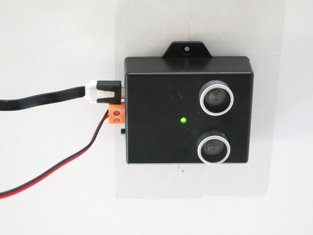
Today I am very excited to introduce OpenSprinkler Bee (OSBee) 2.0: it’s an open-source, WiFi-enabled, universal sprinkler controller. It is suitable for garden and lawn watering, plant and flower irrigation, hydroponics, and other types of watering project. This is the first OpenSprinkler product built upon the popular ESP8266 WiFi chip. It’s designed primarily for latching solenoid valves, but can also switch non-latching solenoid valves (such as standard 24VAC valves), low-voltage fish tank pumps (which can be used to feed water to flower pots and indoor plants), and other types of low-voltage DC valves and pumps. All of them can be powered from a single USB port. This is made possible by using a unique circuit design that leverages a boost regulator and a new solenoid driver circuit. Hence I call it a Universal sprinkler controller. Among the software features, it introduces the concept of Program Tasks, which provides maximal flexibility in programming the zones. In contrast to the first version of OSBee, which was in the form of an Arduino shield and relies on an additional Arduino, OSBee 2.0 is a standalone controller with built-in WiFi, OLED display, laser cut acrylic enclosure, and can switch up to 3 zones independently.

Here is not-so-short video introduction to OSBee 2.0:

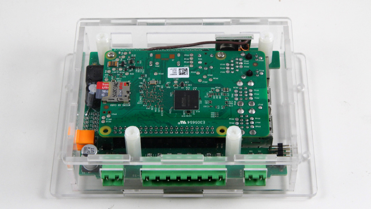
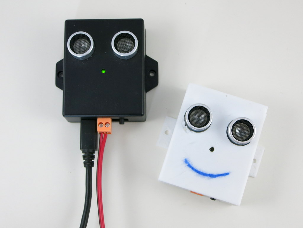
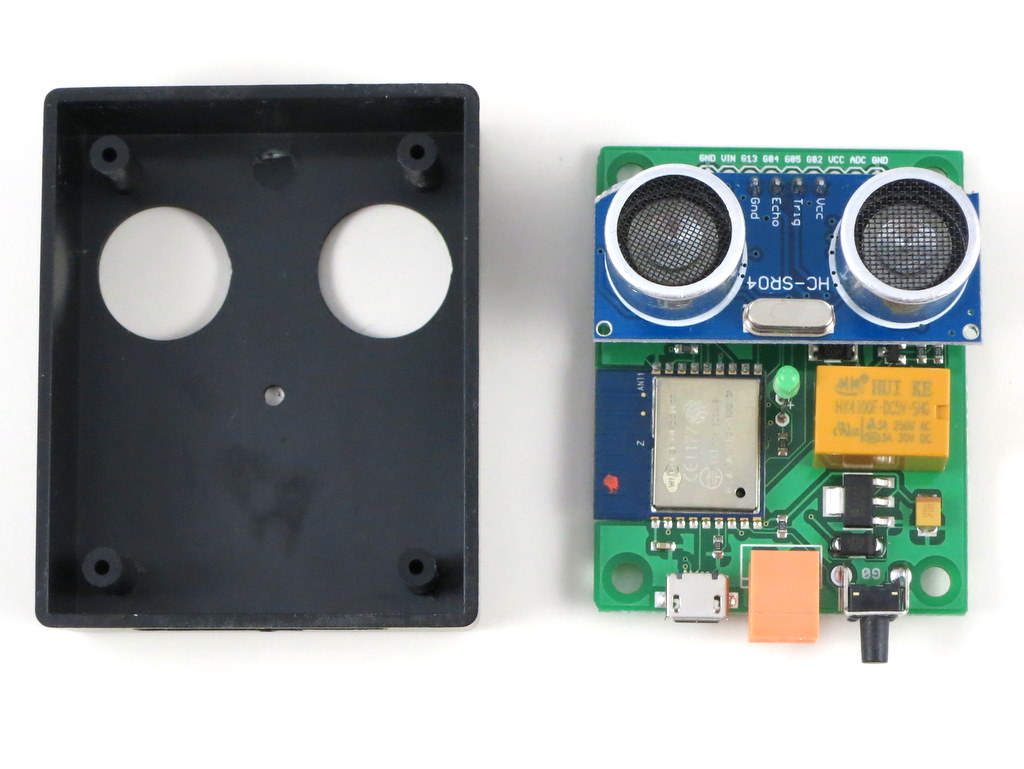
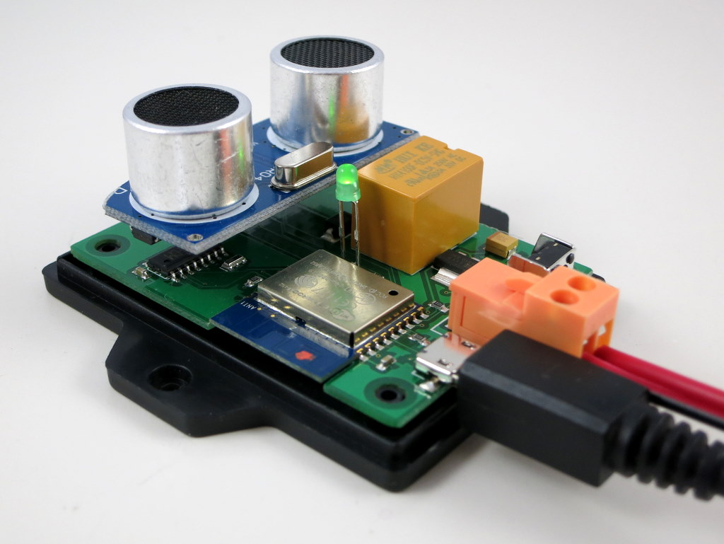
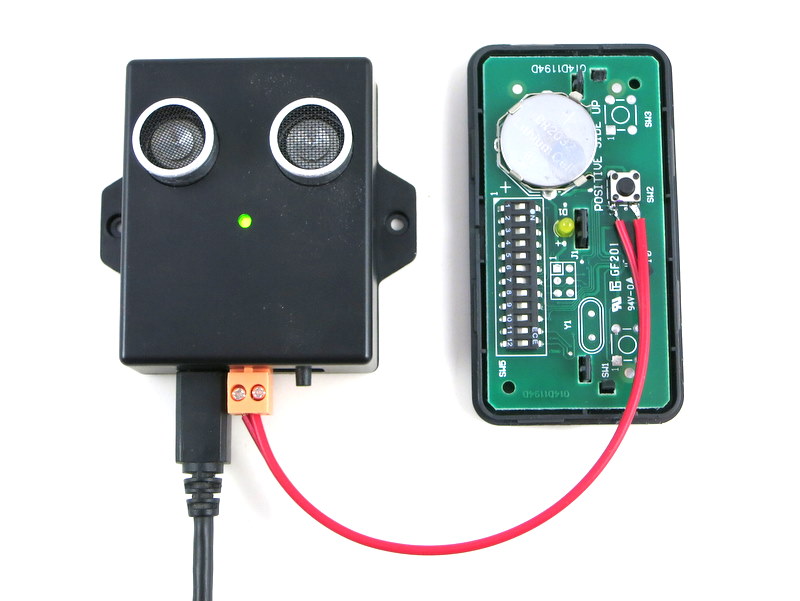
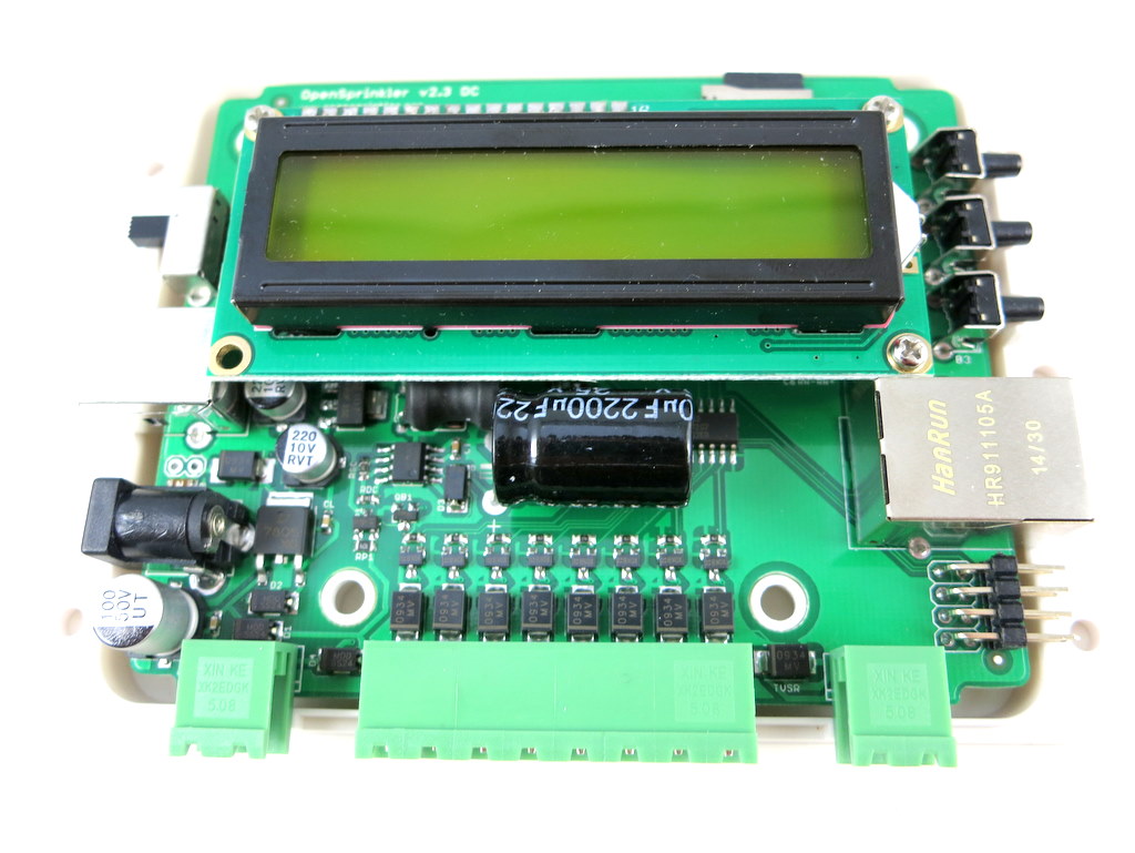
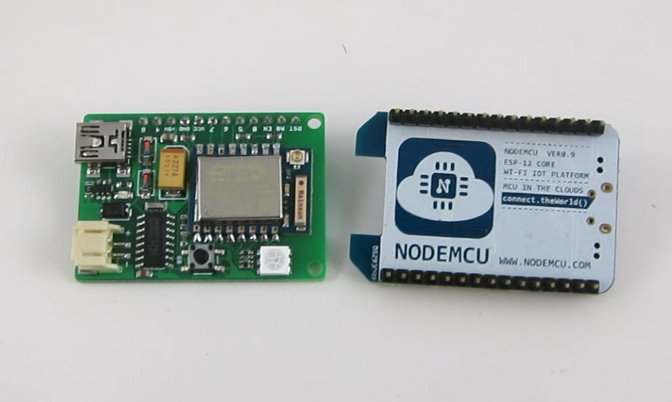
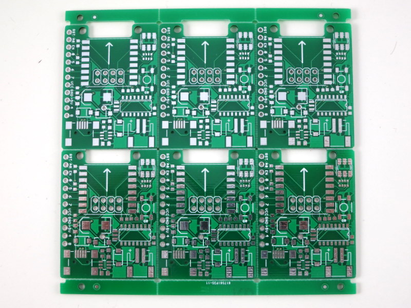
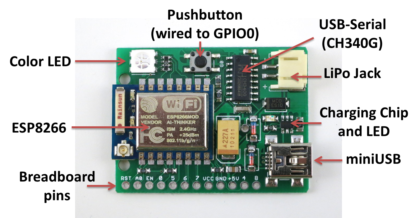
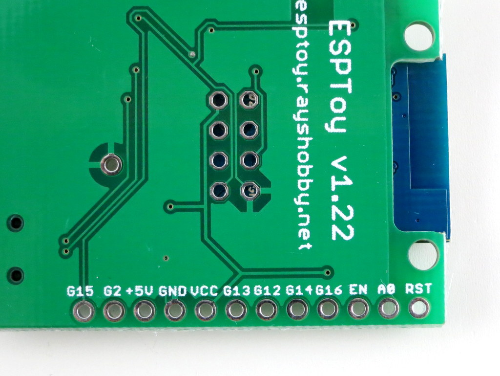
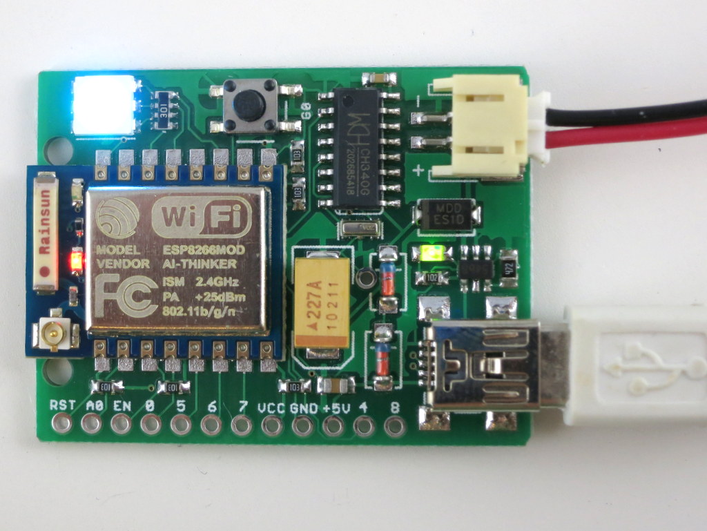
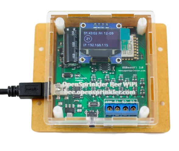
Here are two photos of the OSBee 2.0 circuit board:

osbeewifi_1osbeewifi_2

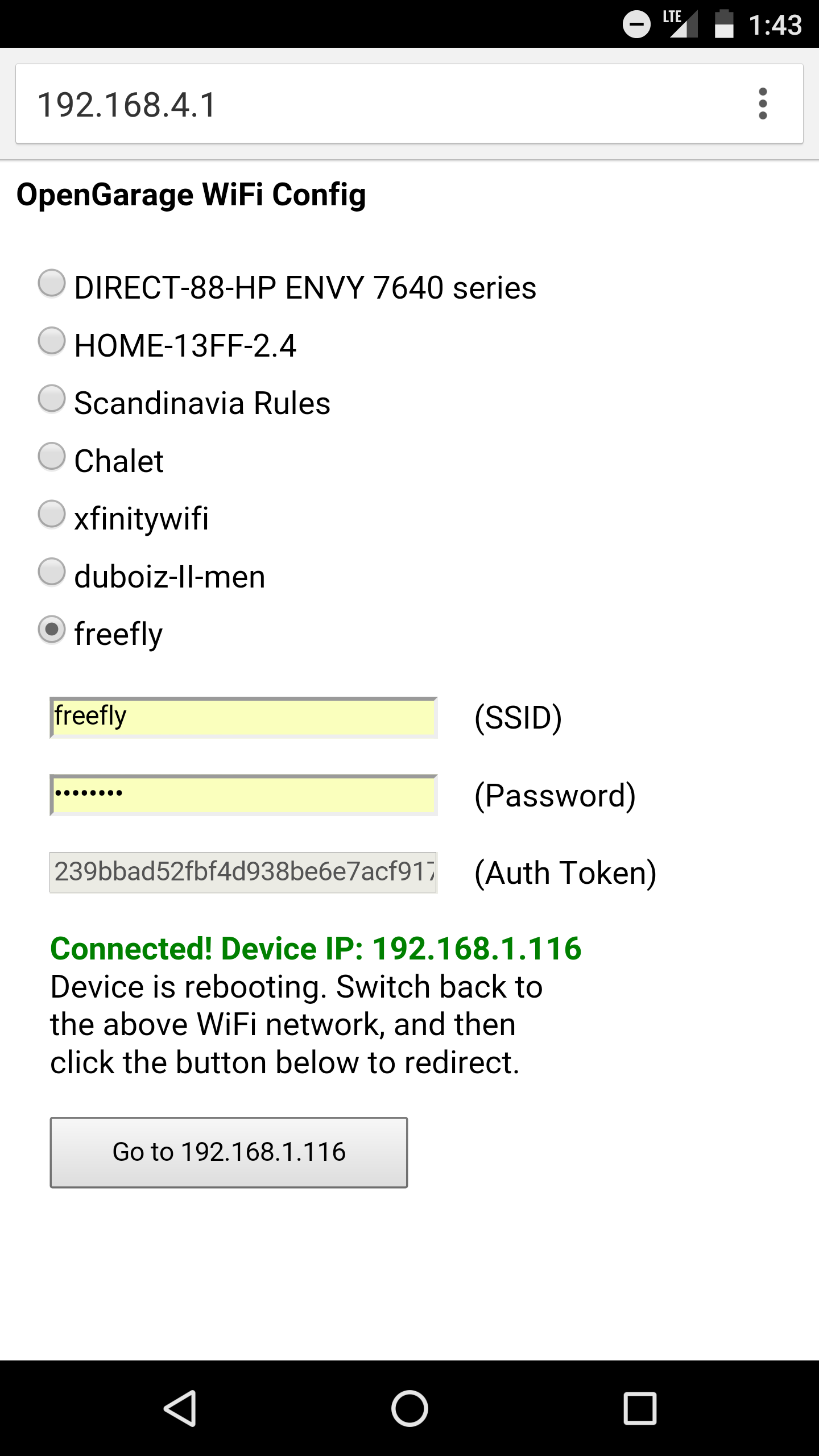
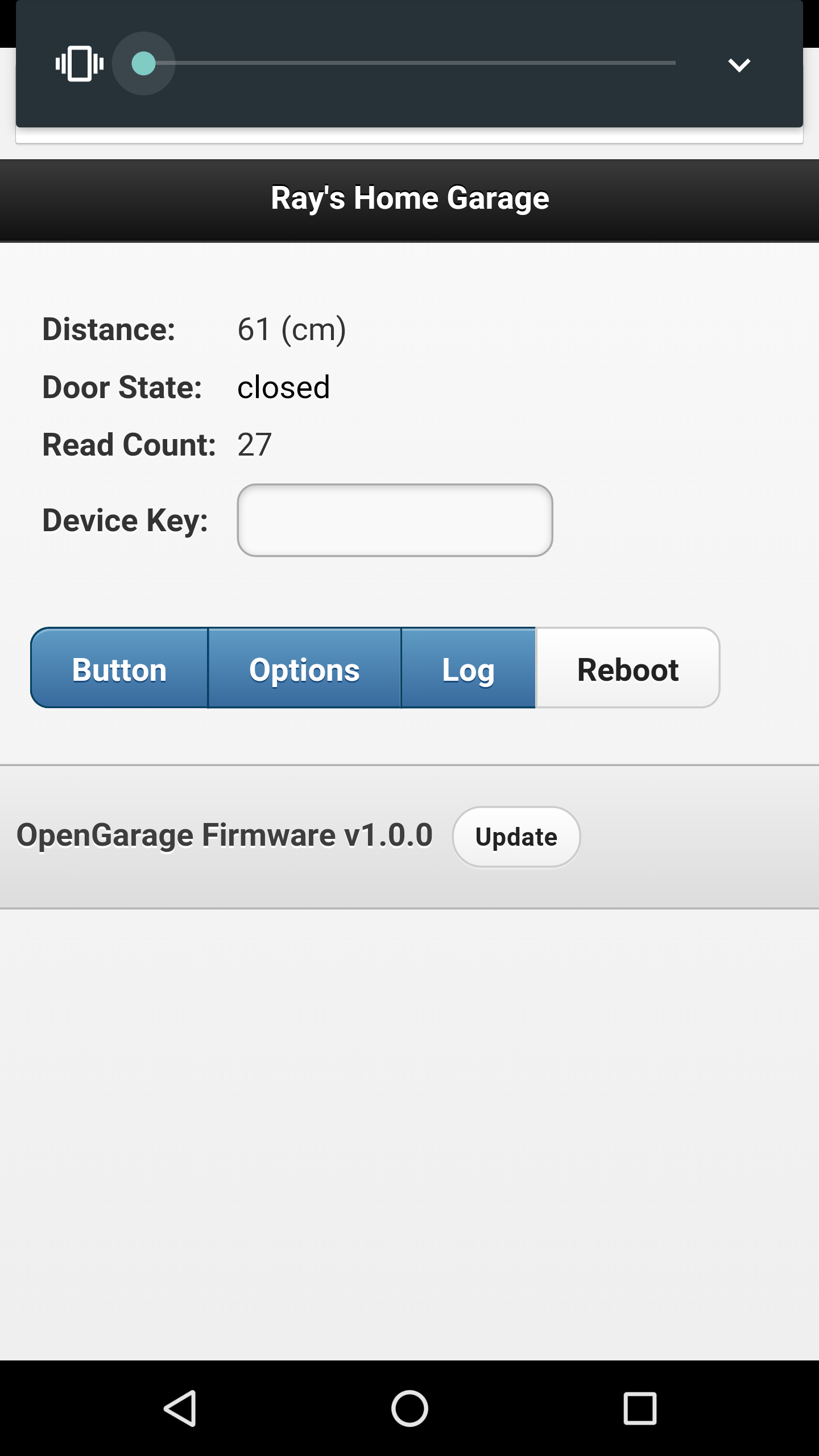
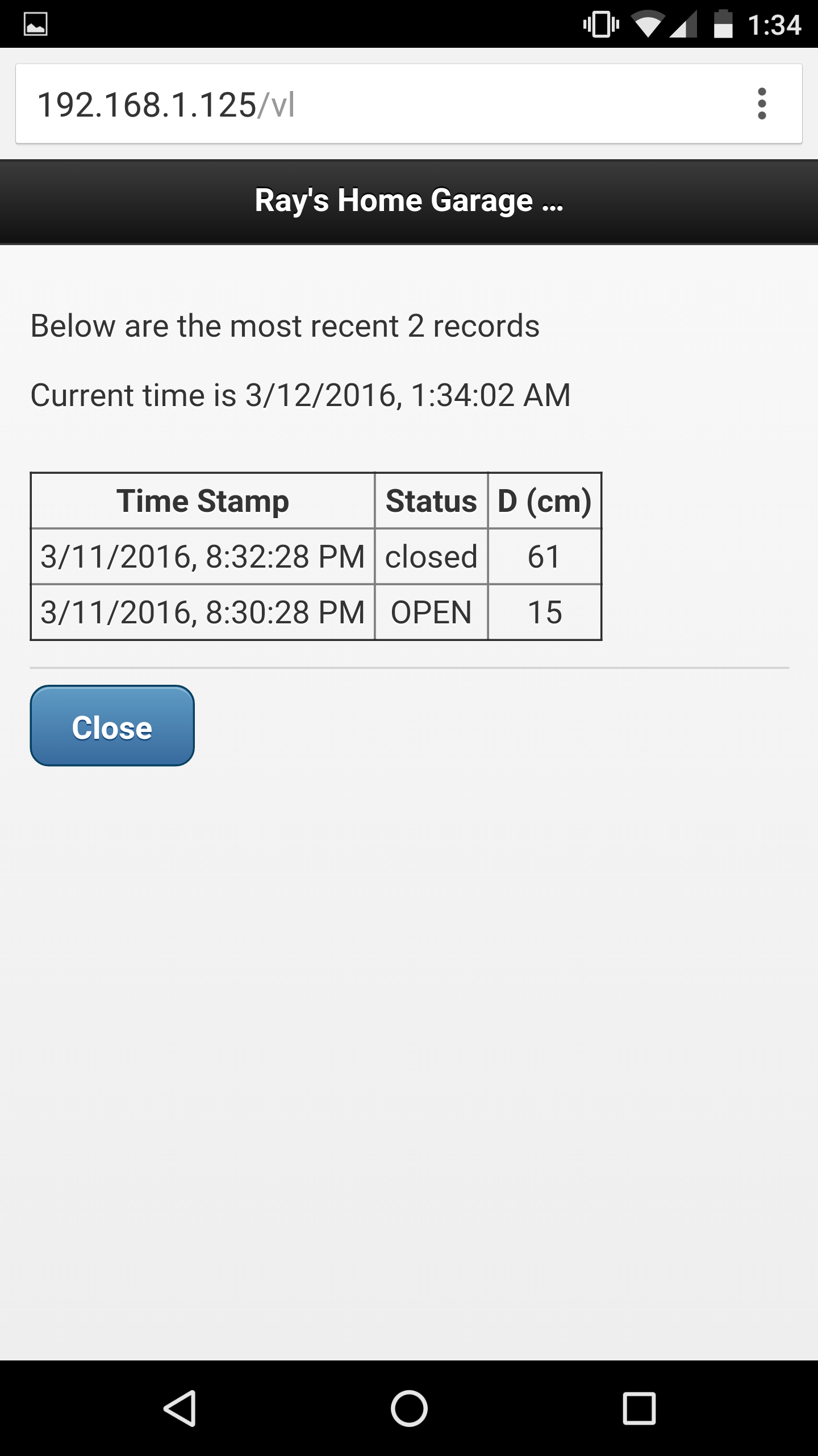
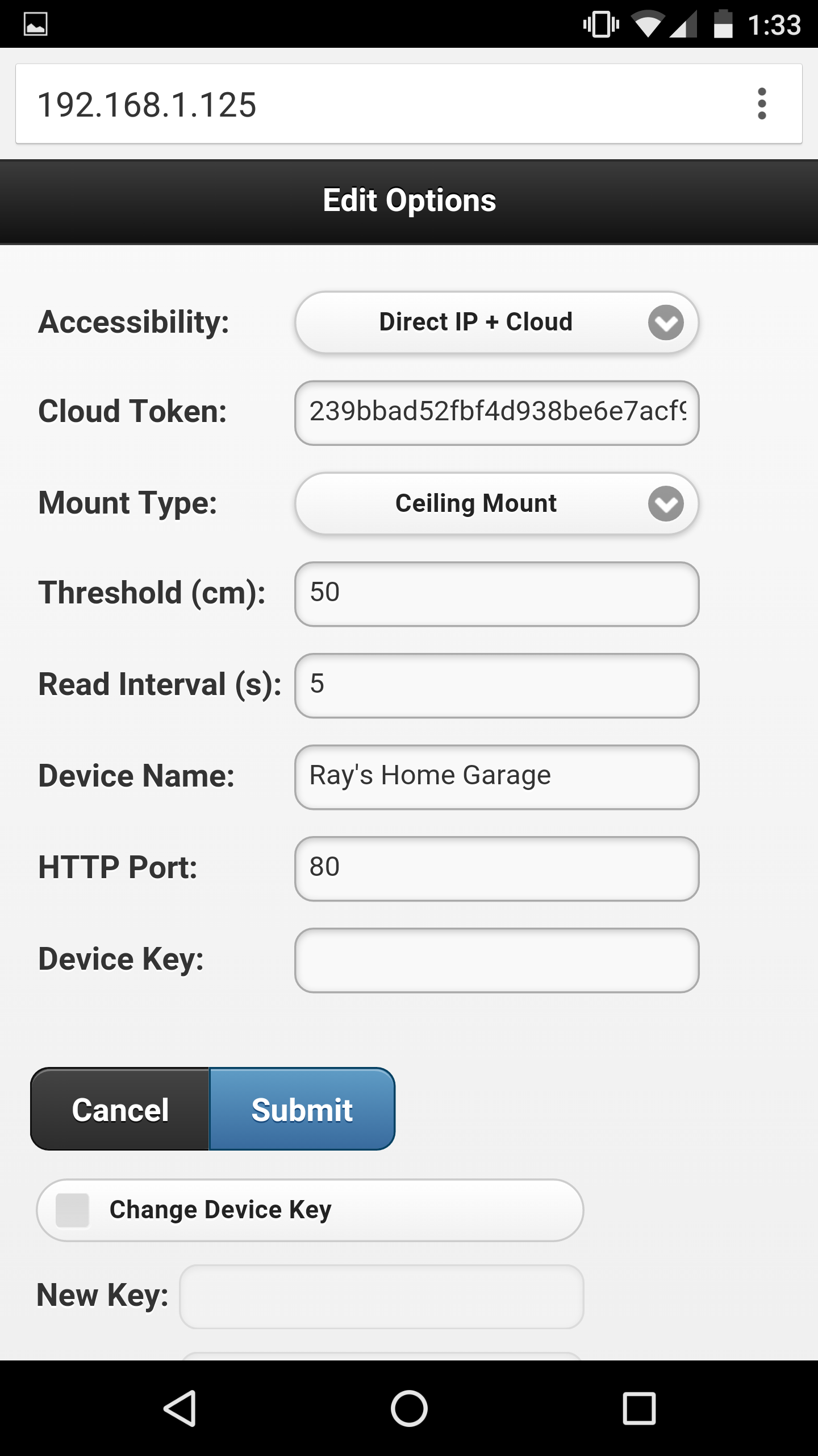
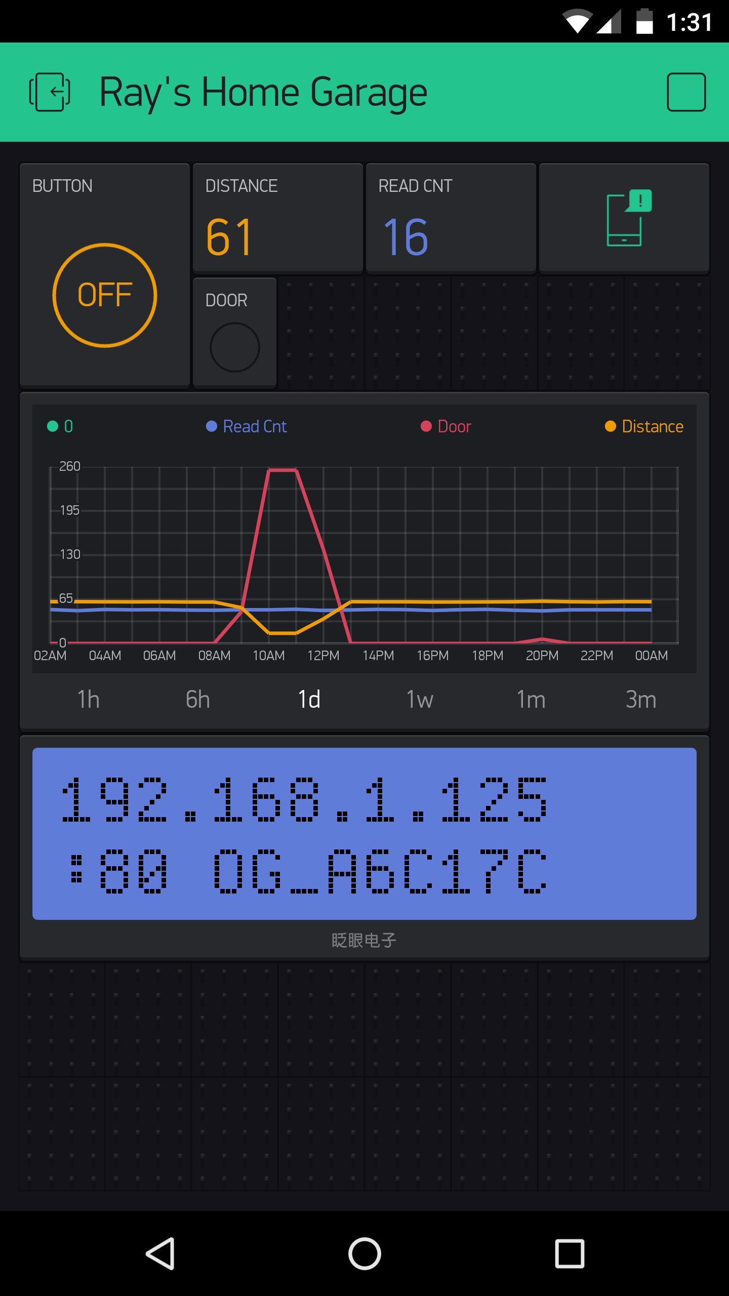
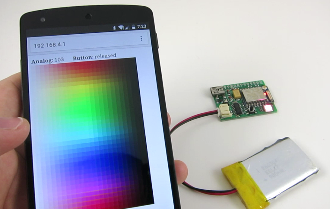
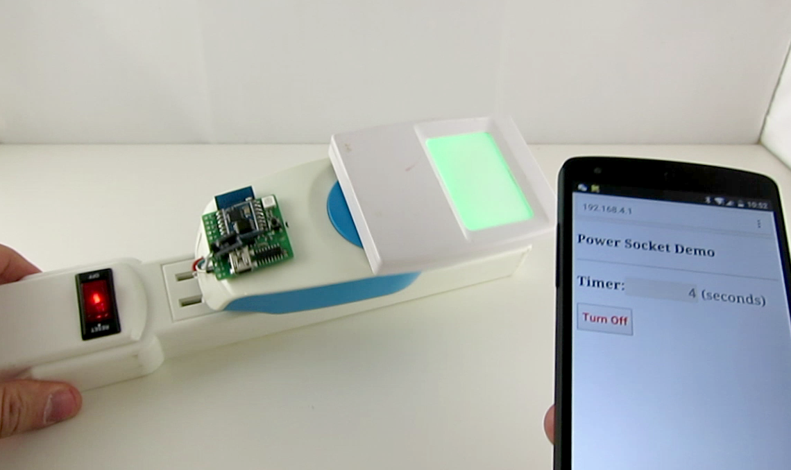
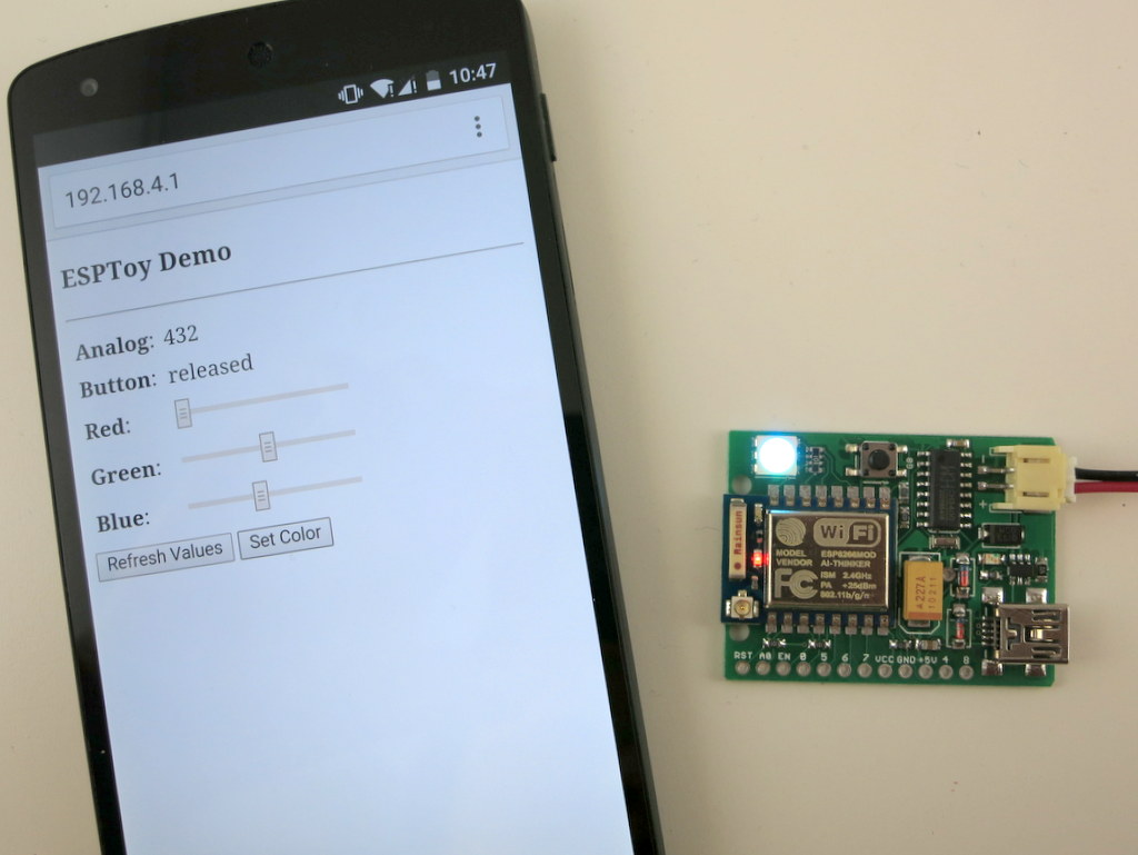
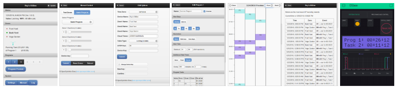
Screenshots of the web interface and Blynk app:
osbee_screenshots

In summary, in terms of Hardware Design, it has the following features:

  • A single ESP8266 chip serves as the microcontroller and handles WiFi connectivity.
  • On-board 128×64 OLED display, real-time clock with backup battery, USB-serial chip. Can switch up to 3 zones independently.
  • Boost converter and a new H-bridge design that allows the same controller to switch both lathing and non-latching solenoid valves, all powered from a single 5V USB port.
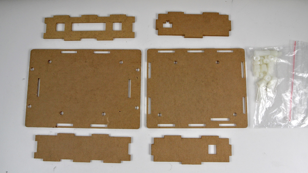
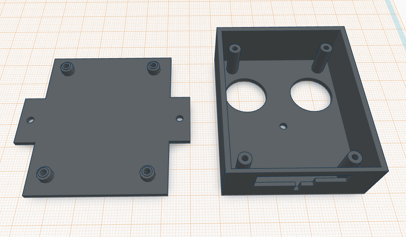
  • An easy-to-assemble laser cut acrylic enclosure.

In terms of Software Features:

  • It has a built-in web interface that allows you to easily change settings, perform manual control, and create automatic sprinkler programs. It also provides logging and program preview features.
  • It introduces Program Tasks to allow maximal flexibility in programming zones. For example, you can define arbitrary ordering of zones, have multiple zones run at the same time, and insert delays between tasks. Zone water time is programmed at precision of seconds.
  • It allows remote control through the Blynk app and Blynk cloud server.
  • Firmware update can be performed either wirelessly using the web interface (OTA), or through the on-board USB port with a USB cable.

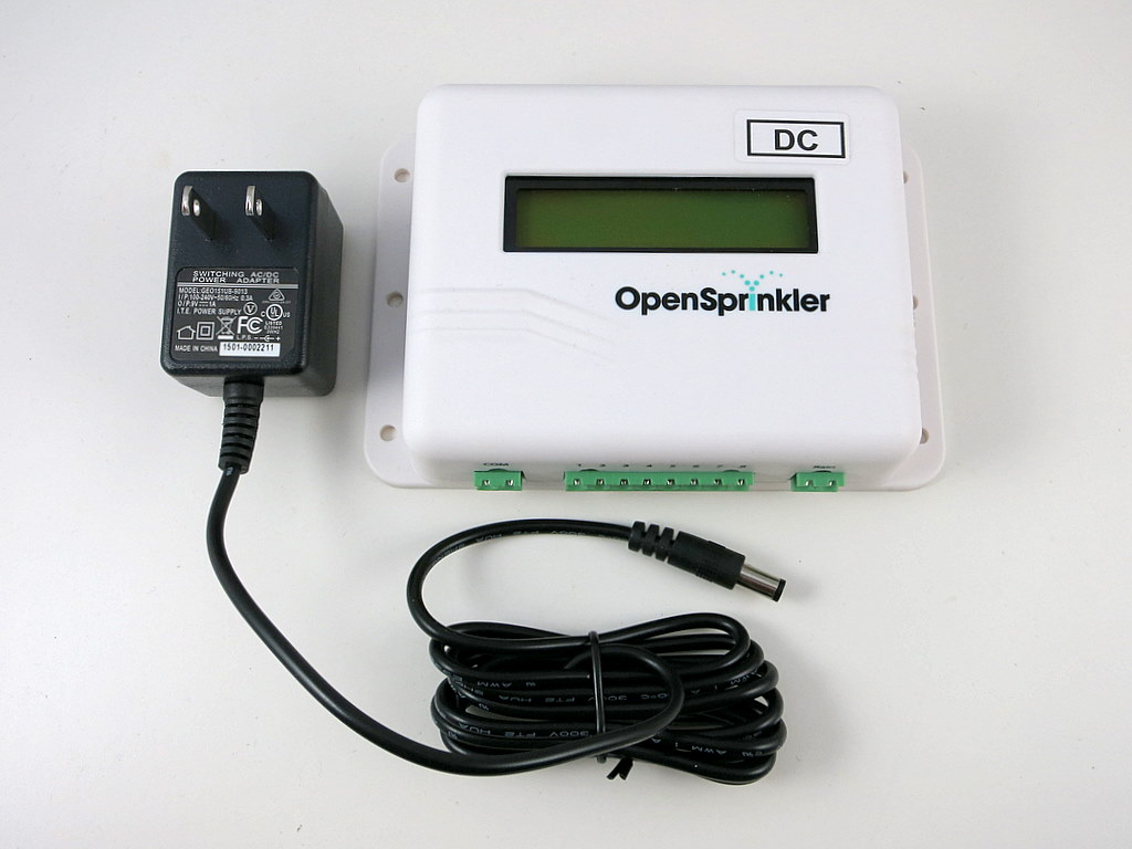
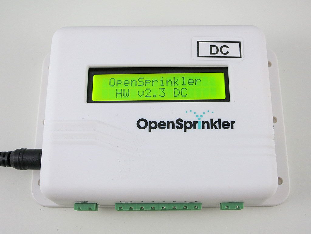
It improves upon the current OpenSprinkler 2.3 by adding built-in WiFi capability, and using a unified solenoid driver that can handle both latching and non-latching solenoid valves. On the other hand, it can only switch up to 3 zones, and the number cannot be expanded. It’s also missing a few advanced features at the moment, such as weather-based water time, virtual stations (e.g. HTTP and RF stations), and support for sensors. Some of these features are purely software, and can be easily added in the future.

OpenSprinkler Bee 2.0 is now available for purchase at our online store:

The package includes a fully assembled OSBee 2.0 circuit board, laser cut acrylic enclosure, instructions, USB cable, and optionally an USB adapter.


Resources and Technical Details

OSBee 2.0 is an open-source project. Its hardware schematic, firmware source code, user manual, and API document are all available at the OpenSprinkler Github repository (look for the prefix OSBee in the repository).

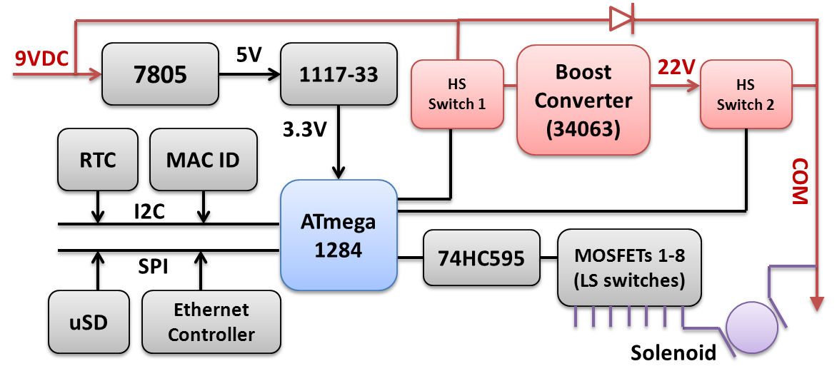
Below I will briefly go over the technical details of the boost converter and the solenoid driver, as I think it’s an interesting design that’s potentially applicable elsewhere. The boost converter is borrowed directly from the OpenSprinkler DC circuit. It’s a simple MC34063-based boost regulator that bumps the input 5V up to 24V DC, and stores the charge into a 2200uF capacitor.

osbee_circuit_1

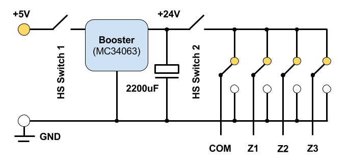
The Booster is controlled by two MOSFET-based high-side switches. The first one controls the input power: the microcontroller uses it to feed the input 5V to the booster, which quickly raises the voltage to 24V. After a couple of seconds, high-side switch 1 is turned off and the microcontroller prepares the states of the half H-bridges (COM, Z1, Z2, Z3). Let me first explain how the states are set for Latching solenoids. The solenoids for the three zone are connected between COM-Z1, COM-Z2, and COM-Z3 respectively. Normally all four half bridges are in ‘High’ state, so the net voltage across every solenoid is 0. To activate a solenoid (say Z1), the corresponding half-bridge will be pulled down to ground (i.e. ‘Low’ state). The microcontroller then turns on high-side switch 2 momentarily to dump the charge from the 2200uF capacitor to the solenoid. This turns on the valve. To deactivate the solenoid, the microcontroller pulls all half-bridges to Low, except the zone that is to be deactivated which remains in High state. It then turns on high-side switch 2 momentarily, again dumping the capacitor charge to the solenoid, but now in reverse polarity, thus closing the valve. This is basically how it operates latching solenoids.

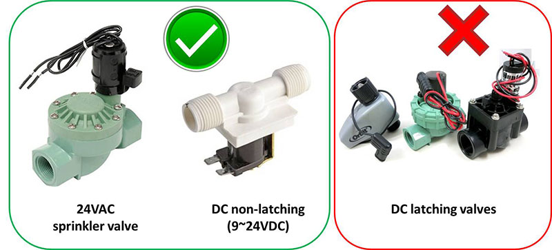
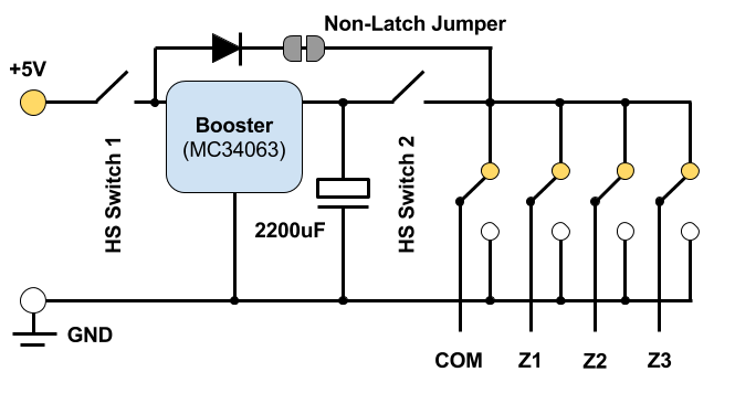
So how does the same circuit work for Non-Latching Solenoids, such as 24VAC valve commonly used in residential sprinkler system? It turns out that just like latching solenoids, non-latching ones also require a pretty high impulse current (called inrush current) to get activated. The difference, however, is that to keep it on, it needs to draw current continuously from the power source. When the power cuts off, the solenoid is deactivated. This is called the holding current and is considerably lower than the inrush current. So to operate non-latching solenoids, all I need is an additional diode that provides a path from the input 5V to the solenoids to provide the holding current. This diode could be software switched by the microcontroller, but because ESP8266 has very few number of GPIO pins, (and I want to avoid having to use an IO expander), I opted to enable this diode path using a solder jumper. To operate non-latching valves, this jumper needs to be soldered on.

osbee_circuit_2

On the Software side, the firmware uses an option to allow the user to choose the valve type (unfortunately the controller can’t automatically detect the valve type yet). For non-latching valves, the half-bridge states are actually easier to manage than the latching case: now COM is always in ‘High’ state, and Z1, Z2 or Z3 are kept ‘Low’ for as long as needed to keep the valves on. That’s it.

You may be wondering how does this even work for valves rated at 24VAC? How can we drive them using DC, and just 5V? The short answer is that this is due to the way such solenoids behave under AC. Specifically, when you first connect the solenoid to 24VAC, it immediately draws a high inrush current, which reliably energizes the solenoid and opens the valve. Once energized, the solenoid presents a large inductance and high reactance to AC, thus limiting the effective current flowing through it. This results in lower holding current, which is enough to keep it on and saves the coil’s lifespan. We can exploit this behavior and achieve the same effect using a DC-based circuit: the booster produces a high voltage initially to provide the inrush current needed to energize the solenoid, and then lowers the voltage to the input level to provide the holding current. Exactly how much holding current is needed is not clearly defined, but for all 24VAC solenoids I’ve tested, once energized, they can remain on at just 5V input voltage.

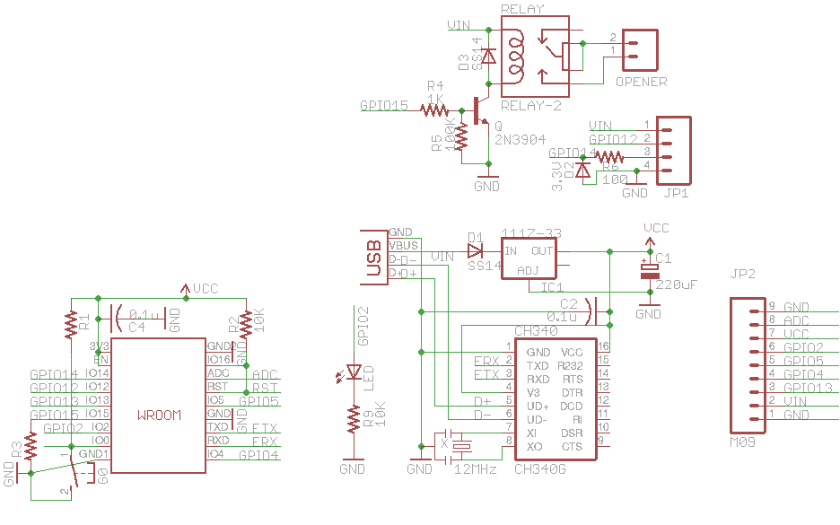
Now we are left with the last part of the technical details: the Half H-Bridge Design. From the circuit diagram above, it seems we can easily implement the half bridges using relays. While this is totally true, relays are bulky, expensive, slow to switch, and difficult to replace. For these reasons, modern electronics prefer to use semi-conductors as much as possible in place of relays. So I decided to use a MOSFET-based H-Bridge design, and it’s a more interesting design than just throwing relays everywhere.

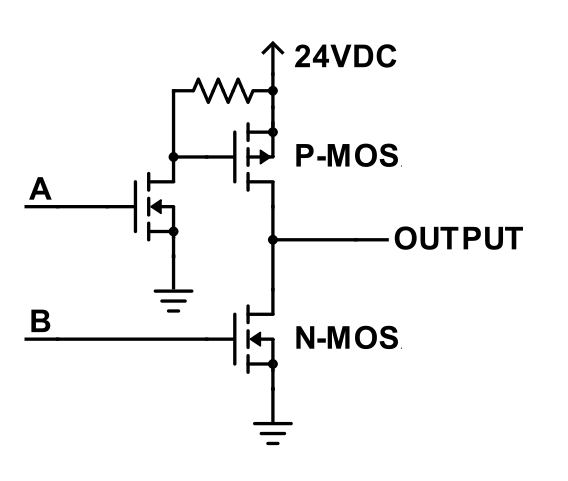
Typically when you want to switch between GND and a voltage considerably higher than the microcontroller’s output, you can use a half H-bridge design as show in the left image below. It uses a low-power N-MOSFET to drive the high-power P-MOS on the bridge, making it possible to use a GPIO pin to switch a high voltage. However, this generally requires 2 GPIO pins (i.e. A and B) per half bridge. Because ESP8266 has a small number of GPIO pins, the challenge is how to use just 1 GPIO pin per half bridge.

osbee_hbridge_1osbee_hbridge_2

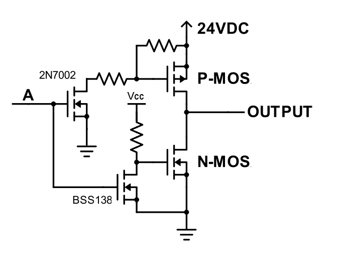
So I came up with a slightly modified half bridge design, as shown in the right image above. It leverages two low-power N-MOSFETs to drive the high-power P-MOS and N-MOS on the bridge. This allows using just 1 GPIO pin (A) to switch the bridge. When A is Low, both input N-MOSFETs turn off, and the gates of the P-MOS and N-MOS are both pulled high, so the P-MOS turns off and N-MOS conducts, pulling the OUTPUT to Low. When A is High, the reverse happens, and the OUTPUT is also High.

Using two input N-MOSFETs also makes it easy to prevent shoot-through problem, which is often an issue with H-bridge. Shoot-through happens when the control signal A transitions from Low to High (or conversely from High to Low), and at some point the P-MOS and N-MOS may both be in conducting state, causing a shorting. To avoid this, I chose to use two different types of input N-MOSFETs: one with lower gate threshold voltage (such as BSS138) and one with higher gate threshold voltage (such as 2N7002). This way, as the control signal A swings between Low and High, the two input N-MOSFETs will turn on and off at different times, ensuring that the P-MOS and N-MOS will not both conduct at the same time. As for the choices of the P-MOS and N-MOS, I opted to use the common AO3401 and AO3400, which provide ample room for continuous current as well as impulse current.

Sorry about going through these nitty-gritty details, but I think these are interesting design notes worth documenting and sharing. Feel free to chime in with your comments and suggestions. Thanks!

OpenSprinkler Black Friday / Cyber Monday Sales Are On

A quick note that our Black Friday / Cyber Monday sales are on now: all OpenSprinkler products are shown in discounted prices right now, and the deal only lasts till Monday Nov 28. This is the only time of the year that we offer discounted pricing, so if you are interested in buying OpenSprinkler, grasp this chance and don’t let it slip away!

If you are wondering whether you need to apply any coupon code. The answer is NO: the price you see is the discounted price. In the past when we used to have coupons, many customers forgot to apply the coupon in the end. To save you the trouble of having to enter coupon code, we directly discount the price, so you will definitely not miss it.

“Alexa, Open Sprinkler Zone 1” — How to Use IFTTT with OpenSprinkler (and OpenGarage)

I just discovered something exciting recently and want to share with you: it’s now possible to use IFTTT with OpenSprinkler and OpenGarage; and because IFTTT support Amazon Echo (Alexa), you can now speak voice command to trigger sprinkler actions. For example, say ‘Alexa, trigger open sprinkler zone 1‘, or ‘Alexa, trigger my garage door‘. I will briefly walk you through the setup process. We will be building support for IFTTT into the firmware soon, to allow for additional features like push notification. For now, the guide below will allow you to trigger actions on OpenSprinkler and OpenGarage with your existing firmware.

Before I proceed, I should give credits to Mike Szelong, who has purchased both OpenSprinkler and OpenGarage, and made both work with Alexa through IFTTT. Thanks to Mike for sending me this tip in the first place. Below let me first explain how IFTTT works.

What is IFTTT?
If you’ve never heard of IFTTT, it stands for If This Then That. With IFTTT, you can set up what’s called ‘recipes’, which hook up ‘triggers’ with ‘actions’. There are many triggers, for example, weather changes, sensor value changes, a new text message, a new twitter message, a new photo upload, or in our case, an Alexa phrase. There are also many actions, for example, send a text message, send an email, post a message on facebook, or in our case, send an web request to OpenSprinkler. With IFTTT, you can easily set up recipes like: ‘if temperature drops below xx degrees, send me a text message’, ‘if there is a new post on my facebook, send me a push notification’, or in our case ‘if Alexa receives a specific phrase, trigger a sprinkler action’. Because it’s so convenient, it has become very popular among Internet of Things.

How does IFTTT send or receive web requests?
IFTTT provides support to what’s called a ‘Maker Channel’, allowing you to use generic web requests (i.e. HTTP commands) as triggers and/or actions. This makes it possible to extend IFTTT support to your own DIY hardware gadgets. For example, to use a Maker trigger, just have your gadget send a web request to IFTTT, and hook it up with an action, such as text message, to enable push notification. This way, when OpenSprinkler starts to run any program, or receives weather changes, it can send a web request to IFTTT, which further triggers a text message or push notification to your phone. Conversely, to use a Maker action, you can set IFTTT to send a web request to your gadget. This way, when it receives an associated trigger, it can send a command to OpenSprinkler to start an action. As both OpenSprinkler and OpenGarage implement HTTP GET commands, they can naturally work with IFTTT through the Maker channel.

Wait, what’s the catch?
There are two. First, to use the device as a trigger, the firmware needs to connect to IFTTT. Neither OpenSprinkler nor OpenGarage has firmware support currently to send web requests to IFTTT, you can’t use them as a trigger yet, but work is underway to add such support to the firmware. Second, to use the devices for action, IFTTT needs to reach the device from the Internet. This requires you to set up port forwarding so that IFTTT can use the public IP address to reach the device. I know that port forwarding is gradually phasing out in favor of cloud-connected devices, but for now we will have to stick with port forwarding.


Now I have explained how IFTTT works, let’s go ahead and create some recipes.

Step 1. Sign up for an IFTTT account
Go to ifttt.com, click on ‘Sign up’ to register an account. You will walk through a simple tutorial to learn the basics of IFTTT.

Step 2. Enable Maker channel
Click on ‘Channels’ at the top, then search for ‘Maker’ and under ‘Developer Tools’ select the Maker channel, and click on ‘Connect’. You will be assigned a ‘key. At the moment you don’t need the key, so you can ignore that for now.

ifttt1

Step 3. Set up a recipe
Click on ‘My Recipes’ at the top and then ‘Create a Recipe’. Select a trigger (i.e. this) — for example, search ‘sms’ and select SMS as a trigger. Input your phone number and a verification pin. Then select a trigger method, such as ‘Send IFTTT an SMS tagged’. Then input the tag phrase, such as zone1on. This means every time IFTTT receives a text message with that particular phrase, it will trigger an action.

ifttt2ifttt33

Next, to choose an action (i.e. that), search for ‘Maker’, and click on ‘Make a Web Request’. This is where you need to input the HTTP command. You will need to type in your home network’s external IP address, external port number (that maps to OpenSprinkler through port forwarding), followed by a supported HTTP command (check API document listed below), device password, and required parameters. The example below turns on zone 1 (i.e. sid=0) for 10 minutes (i.e. 600 seconds). For ‘Method’, select ‘GET’, and you can leave Content Type and Body empty. If you are not sure whether the command works or not, simply copy and paste the URL you constructed to a browser, and if the returned message has {‘result’:1} that means it has succeeded.

ifttt5
Click on ‘Create Action’ to finish.

In case you’ve got lost, here are some useful links that you may need to refer to:

Step 4. Test the recipe
To test the above example recipe, send a text message #zone1on (don’t forget the pound sign!) to the IFTTT phone number (this is the same phone number you received a text from when you verified your phone with IFTTT). If everything is set up correctly, your sprinkler zone 1 will start watering for 10 minutes!

Step 5. Use Alexa to enable voice command
Now that I’ve walked you through a basic example, you can experiment with using Alexa to enable voice command. You obviously need to have an Alexa (Amazon Echo) for this to work. The recipe is largely the same as the above text message example, except that for trigger (i.e. this) you will select Alexa, and give it a phrase. Now when you speak that phrase to Alexa, it will trigger the action. How exciting! Don’t forget that you need to say ‘Alexa, trigger xxx’ where xxx is the phrase. The ‘trigger’ keyword is kind of like the pound sign in the text message.

If you have an OpenGarage, you can also follow the OpenGarage API to set up web requests and get Alexa to open / close the garage door for you.

Currently as the phrase is fixed / static, there is no easy way to parametrize the phrase. For example, you can’t say ‘trigger open zone 1 for blah minutes’ where ‘blah’ is a variable like 10, 20 or any positive integer you want. I am sure this would be possible in the future though.

Next Step: Notifications
As I said, another popular use of IFTTT is for email / text / push notifications. For doing so, the device needs to send HTTP commands to IFTTT. Upon receiving the request, it can trigger an action such as sending you an email or text message. Work is under way to add this support to both OpenSprinkler and OpenGarage firmware, and hopefully they will be ready soon!

OpenSprinkler Pi Laser Cut Enclosure

For a long time, OpenSprinkler Pi (OSPi) has been using the OpenSprinkler injection molded enclosure. While this has worked fine, the enclosure is not particularly designed for OSPi, leaving some cutouts not aligned with Raspberry Pi. Recently I have started learning to design enclosures using laser cut acrylic pieces. This is a great way to design fully customized enclosures for circuits. Today the first batch of laser cut enclosures for OSPi has arrived, and we will be shipping these with OSPi kit right away.

Here is a picture of the enclosure pieces and screw bag:
img_1262

And here is a picture of the enclosure after it’s fully assembled. After removing all the protective papers from the acrylic pieces, it produces a fully transparent look of OSPi, which is pretty cool.
img_1261

It’s not necessary to remove all the protective papers. I would recommend leaving the papers on except the top panel. This way it gives a kind of wooden texture of the enclosure, and adds more protection to the enclosure.

Below is an instructional video that walks you through the assembly steps:

I will make a separate post shortly that explains how to automate the design of such laser cut enclosures.

Introducing OpenGarage: an Open-Source WiFi Garage Door Opener

News and Updates

  • We’ve recently found a technical issue with Blynk’s QR code scan feature that makes the Blynk app not work properly on some iOS devices. The symptom is that the app can receive push notifications but the distance value, read count, and LCD widget are not updating. Please check this forum post for solutions. This seems to only affect iOS devices.
  • OpenGarage User Manual (PDF) is available on Github.
  • OpenGarage Firmware 1.0.4 API document is available on Github.
  • Blynk connection issue: recently Blynk updated their cloud server, causing Blynk app to not be able to communicate with OpenGarage. The solution is to update OpenGarage firmware to 1.0.4.
  • Reboot cycle issue: we’ve found a few reports of ‘reboot cycle’ where the controller continuously reboots. This issue has finally been sorted out. The solution is to reflash the firmware using a microUSB cable.


Today I am very excited to introduce you to OpenGarage — an open-source, universal garage door opener built using the ESP8266 WiFi chip and the Blynk app. I’ve wanted to finish this project for a while, as there have been multiple occasions where I left the house in a hurry and forgot to close my garage door, or locked myself out of the house, or had to let a friend or handyman in while I was away. Having a WiFi-based garage door opener (which I can access remotely using my mobile phone) would be super convenient. Recently as I started learning about ESP8266, I found it to be the perfect platform to help me complete this project.

A quick note: this blog post is temporarily the main landing page of opengarage.io. A more professional-looking site is under construction and should be ready soon. Also, the first production run has been ordered, and they should be ready to ship in 2 weeks of time. If you are interested in OpenGarage, you can place your order at rayshobby.net/cart/og.

Here is a video introduction that gives you a quick walk-through:

Here are some head shots of the OpenGarage controller:

IMG_1068IMG_1069

IMG_1007IMG_1070

I made the prototype version using a 3D printed case, and the final version using an off-the-shelf case with custom cutouts. Two pictures of the circuit board are shown on the right above. With OpenGarage, I can now check my garage door status wherever I am, open or close the door remotely, and check the record of recent events through the log and history graph. The controller supports a built-in web interface with embedded HTMLs, and remote access through the Blynk app. The built-in interface is used for local access and changing configuration/settings, while the Blynk app is used for remote monitoring and control.

Hardware-wise, it’s really simple. It consists of:

  • an ESP8266 (WROOM-2) WiFi chip;
  • an ultrasonic distance sensor (HC-SR04);
  • a relay (for triggering garage door actions);
  • a pushbutton and indicator LED;
  • a microUSB connector and CH340G USB-serial chip.

Mounting. The controller is typically mounted to the ceiling at the garage, with the distance sensor facing down. When the garage door is closed, it reads the distance to the ground, or the top of your car if you’ve parked in the garage. When the door opens and comes up, the sensor reads the distance to the door, which is a much smaller value. So by checking the distance value, it can tell if the door is open or closed. The distance value can also tell you if your car is parked in the garage or not, which is an additional benefit that can be useful at times.

For roll-up garage doors, the ceiling mount would not work. Instead, you can mount it to the side of the door, with the sensor facing the outside. This way the logic is reversed: if the distance reading is small, it means the door is closed, and vice versa.

Interfacing with Garage Door System. OpenGarage uses a relay to simulate door button clicks. For most garage door systems, you can simply connect the two wires from the OpenGarage controller to where you would normally insert your door button wires into. The only exception is the most recent Security+ 2.0 systems, which come with a yellow learn button and antenna. These openers use secure door button codes, but you can still interface with them through a compatible door button.

IMG_1066IMG_1009IMG_1008IMG_1073

Alternatively, you can take apart an existing garage door remote, solder two wires to the button, and connect these two wires to OpenGarage. This way, the relay clicks simulate pressing the button on the remote. As long as you have a remote that works with your garage door system, this approach would always work.


Web Interface and Blynk App. The controller has a built-in web interface with embedded HTMLs, implemented using JQuery Mobile. It’s used for WiFi setup, local access (directly using IP) and changing configurations/settings. The controller also supports remote access through the Blynk app, which is a cloud-based service that’s really easy to use. Before proceeding, it’s recommended that you install the Blynk app, create an account, log in, and scan the OpenGarage app QR code to replicate the project inside Blynk. Then go to the project settings and copy the authorization token (32-digit hex code). This way, immediately after the setup step, you can use Blynk to access OpenGarage.

1_og_ap2_og_home3_og_log4_og_options6_og_blynk_app

Initial Software Setup. OpenGarage is powered by a microUSB cable. At factory default settings, it boots into Access Point (AP) mode, creating an open WiFi network named OG_xxxxxx (where xxxxxx is the last 6 digits of MAC). Use your phone or a computer to connect to this network, and then open a browser and type in 192.168.4.1 to access the AP homepage. You will see a list of nearby WiFi networks scanned by the controller. Select (or manually type in) the ssid, input the password, and paste the Blynk token (if you don’t have it, just leave it empty). Then click on ‘Connect’. The controller will go into AP+STA mode, attempt to connect to your router, and report back its assigned IP address.

Once connected, it will reboot into STA-only mode. At this point, switch your phone back to your home WiFi, and click the redirect button (or manually type in the assigned IP) to access the device homepage.

LED and Button Functions. The LED serves mainly as an indicator: in AP mode, the LED blinks rapidly; and in station mode, the LED blinks briefly when the controller reads the distance sensor, which is once every few seconds (configurable). The button (connected to GPIO0) has the following functions: a short click triggers a relay click; and a long press triggers a factory reset (see below). The button can also be used to enter bootloading mode: if the button is pressed when the controller is powered on, ESP8266 will enter bootloading mode. This is useful if you want to upload a firmware through USB (instead of using OTA update).

Reset to Factory Default. At any point, you can press and hold the pushbutton for 5 seconds or more until the LED stays on, then release the button to reset the controller back to factory default.

Built-in Web Interface. At the homepage you can check the distance readings, door status, and a read count value which increments every few seconds as the controller reads the distance sensor. The read count is basically a ‘heart beat’ that indicates if the controller is communicating with your browser or not. You can trigger a button click or reboot the controller. These actions are protected by a device key, which is by default opendoor.

Click the Options button to open the ‘Edit Options’ page. Most of these are pretty obvious. The one you may need to tweak is the distance threshold, which the controller uses to tell if a door is open or closed. Basically, measure the distance from the sensor to the door (when it’s fully open), and that to your car, and pick a value in between the two. The settings are all saved in a configuration file in the flash memory, so they won’t get lost when the power is down.

At the homepage, click the Log button to open the log page. There you can see the list of recent events. The homepage also shows the current firmware version. Next to the version number is an ‘Update’ button, which allows you to upload a new firmware through the web interface (thanks to the OTA update feature available to ESP8266).

Blynk App. For remote access, the Blynk app is really easy to use. Once you’ve set a token, OpenGarage will communicate with Blynk’s cloud server and report its status. Like the built-in web interface, the app allows you to check distance readings, door status, and trigger a button click. Additionally, it provides a history graph that visualizes previous events, and push notifications when the door opens or closes (note that Blynk limits push notifications to no more than one per minute).


Resources and Technical Details

I’ve published the hardware design files and firmware code in Github. Those who are interested in the technical details can go to:

to find out all the low-level details. These include the circuit schematic and PCB (in EagleCAD format), 3D model of the enclosure, OpenGarage Arduino library, and instructions to compile the firmware. If you are interested in modifying the 3D printable enclosure, go to tinkercad.com, log in, and search for ‘OpenGarage’ and you should find the 3D model I created there.

og1.0enclosure

If you want to extend the functionalities of OpenGarage, there are several spare pins which are mapped out on the PCB for adding additional sensors etc.

Overall it has been a very pleasant experience using ESP8266 for this project. It’s inexpensive, powerful, and has active community support. I can’t think of any reason why not to use it for all my future projects 🙂

If you are interested in buying OpenGarage, you can place your order at rayshobby.net/cart/og.


FAQ

Q: How do I update OpenGarage firmware?
A: Compiled firmwares are all released on
OpenGarage github. For example, here is the direct link to firmware 1.0.4:
https://github.com/OpenGarage/OpenGarage-Firmware/raw/master/Compiled/og_1.0.4.bin
Before proceeding, note that once a new firmware is uploaded, the log will be erased, so keep a copy of the log if you need.

  • Use the web interface to update firmware (click the ‘Update’ button at the bottom of the homepage or Options page).
  • If the built-in web interface is not responding, do a factory reset (i.e. pressing the button for 5 seconds or more), then follow the setup steps but leave the cloud token empty (to avoid any potential Blynk connection issues). Once firmware is updated, go to the Options page and put in the Blynk token, make sure the Accessibility is set to ‘Direct IP + Cloud’.
  • If neither of the above work, you can use a USB cable to flash a new firmware (see instructions below).

After updating firmware, check the bottom of the homepage and make sure the firmware version is correct.


Q: How do I reflash the firmware using a microUSB cable?
A: In the event that the controller cannot boot correctly (such that you can’t have access to over-the-air update), you can reflash the firmware via a microUSB cable.

Step 1: Driver. Depending on your operating system:

Step 2: Bootloading mode and serial port.
Let the device enter bootloading mode. To do so, get a microUSB cable, plug the smaller end to the device’s USB port, then press and hold the pushbutton while plugging the cable’s other end to your computer. The LED light should stay on constantly, and you should not hear any buzzer sound. If not, unplug the USB cable and redo this step.

Next, the device should appear as a serial port and you need to find out the serial port name:

  • Windows: the serial port name is COM? where ? is a number. You can find out the port name in the notification area, or in Device Manager — Serial Port.
  • Mac OSX: the serial port name is /dev/tty.wchusbserial? where ? is a number. You can find out the port name by running ls /dev/tty.wch* in Terminal (i.e. command line).
  • Linux: the serial port name is /dev/ttyUSB? where ? is a number. Run ls /dev/ttyUSB* in command line to find out.

Step 3: Reflash firmware.

Download the OpenGarage reflash package and unzip it. The package includes esptool, nodemcu firmware, and OpenGarage firmware. Open a Terminal (i.e. command line window), cd to the folder where you unzipped the package. Depending on your operating system, run the following command (assuming the device is in bootloading mode):

  • Windows: esptool.exe -cd ck -cb 230400 -cp COM? -ca 0x00000 -cf nodemcu.bin
    where COM? is the serial port name you found in Step 2 above.
  • Mac OSX: ./esptool_mac -cd ck -cb 230400 -cp /dev/tty.wchusbserial? -ca 0x00000 -cf nodemcu.bin
    where wchusbserial? is the serial port name you found in Step 2 above.
  • Linux: sudo ./esptool_lin32 -cd ck -cb 230400 -cp /dev/ttyUSB? -ca 0x00000 -cf nodemcu.bin
    where ttyUSB? is the serial port name. If you use Linux 64-bit, use sudo ./esptool_lin64 instead.

If you encounter any error, check if the device is in bootloading mode. Repeat Step 2 to enter bootloading mode before flashing.

Finally, once the nodemcu firmware is flashed, re-enter bootloading mode (Step 2) and run the above esptool flashing command again, except replacing nodemcu.bin at the end with og_1.0.4.bin. This completes the firmware reflashing.


Announcing the First DC Powered OpenSprinkler (v2.3 DC)

After several months of continued development, I am excited to announce the release of the first DC powered OpenSprinkler — v2.3 DC. This version uses a 9V DC universal power adapter, and is designed to work with both standard 24V AC sprinkler solenoids as well as DC (e.g. 12V DC) non-latching solenoids. Below are two pictures.

IMG_0825IMG_0823


Buy OpenSprinkler v2.3 DC from Rayshobby Shop.


As explained in a previous blog post, the main motivation behind this is to make it easy to source the power supply for OpenSprinkler, particularly for International customers outside of US/Canada. As you know, different countries use different mains voltage standard. In US/Canada, the mains voltage is 110V AC; but in most other countries, the mains voltage is 220V to 240V AC. Because AC adapters are not regulated, you can’t directly use a 24V AC transformer designed for the US market in, say, Germany. You will either need a 220V to 110V step-down converter, or source your own 24V AC transformer. Either case, it’s a pain. On the contrary, DC transformers are much easier to source, and work universally in any country of the world. They are usually cheaper too, because their demand is higher than AC transformers. Therefore it would be ideal to use DC power supply. This is just like how your laptop adapters can work with any mains voltage in the world, so you don’t have to worry about it wherever you travel to.

Given the above benefits of DC, why in the world are sprinkler solenoids designed to work on 24V AC? To explain this, you should read my earlier blog post entitled Understanding 24V AC Sprinkler Valves. In that blog post I analyzed the electrical properties of 24V AC solenoids. They generally require a high impulse (in-rush) current to get energized (often as high as 300 to 500mA), then they will stay on with a relatively low stable (holding) current (e.g. 150 to 250mA). With AC power, the solenoids can automatically achieve this dynamic current adaptation, thanks to the solenoid coils’ electric properties (technically, the inductor’s reactance to AC). This ensures the solenoid will both turn on solidly, and remain on at relatively low power consumption and heat dissipation. The circuit design is also quite simple and straightforward.

But there is no reason why we can’t achieve the same effect with DC. Specifically, there is nothing particular about AC solenoids that they must be driven by AC — they work just fine under DC current. However, you need a more complex circuit to alternate the voltage: it needs to produce a high in-rush voltage to ensure the solenoids are solidly energized, and then reduce the voltage down to produce a relatively low (150 to 250mA) holding current. According to my calculation, 9V DC is ideal for providing the required holding current. On top of that, we just need a boost converter to generate a high in-rush voltage (18~22V) required to energize the solenoids. That’s it — this is how a DC powered OpenSprinkler works on a high level.

If you search online, you can find plenty of people using just 12V DC to power sprinkler solenoids. In my mind, it’s not the most reliable design, as 12V is barely sufficient for producing the in-rush current, and is too much for holding current. As a result, it may not successfully energize the solenoids, and it certainly will shorten the solenoids’ lifetime due to the excessive holding current. That’s why my design uses 9V DC power instead, in conjunction with a on-board boost converter. This provides the optimal holding current as well as in-rush current.

If you still have questions or confusions, hopefully the F.A.Q. below will help you answer your questions.


How is OpenSprinkler v2.3 AC different from v2.3 DC?
OpenSprinkler v2.3 AC uses 24V AC transformer (sold separately), and triacs to drive sprinkler solenoids. OpenSprinkler v2.3 DC uses 9V DC transformer (included in the package), and MOSFETs to drive solenoids. Other than these, the two use the same microcontroller (ATmega1284p) and run the same OpenSprinkler Unified Firmware.

In addition, OpenSprinkler v2.3 DC includes a universal 9V DC power adapter that can be used worldwide. In contrast, v2.3 AC version does NOT include the transformer — US/Canada customers can purchase 24V AC transformer as an optional add-on, but customers in other countries will have to source 24V AC transformers on their own.

What types of solenoid valves can work with v2.3 DC?
Both standard 24V AC sprinkler solenoids as well as DC solenoids (e.g. 12V DC or 24V DC, non-latching type). Keep in mind that v2.3 DC is NOT compatible with latching solenoids.

os23dc_compatibility

What about pump start relay and multiple valves?
We’ve tested a few common pump start relays and they all work well with OpenSprinkler DC. We’ve also tested opening multiple valves simultaneously without any issue.

How can I decide which version to get: AC or DC?
We strongly recommend the DC version for anyone who doesn’t already have a 24V AC transformer, because the DC version includes the transformer. It’s particularly suitable for customers outside of US/Canada as there is no need to source your own power adapter any more.

Also, if you need to control DC solenoid valves, such as 12V DC solenoids, the DC version is your only choice.

On the other hand, if you need to use certain sensors that require 24V AC, such as wireless rain sensors, soil sensors, or solar sensors which require 24V AC, you are better off with the AC version as they can share the same 24V AC power supply.

Does OpenSprinkler v2.3 DC output AC voltage?
No, it does not. It uses completely DC voltage to drive AC sprinkler solenoids. To understand how it works, refer to the explanations above. Because the output voltage is DC, it can also work with DC solenoid valves (non-latching type).

What about expansion boards?
Keep in mind that the DC controller must use DC expansion boards; similarly, AC controller must use AC expansion boards. You should NOT mix and match the two, or your sprinkler solenoids won’t function properly. All DC controllers and DC expansion boards have the label [DC] attached at the front and back of the enclosure.

What’s the operating voltage range for v2.3 DC?
Although v2.3 DC comes with a 9V DC power adapter, you can power it with any voltage ranging from 5~24V DC.

Can you give me more details on how v2.3 DC works internally?
Below is a block diagram of the v2.3 DC circuit. All relevant parts are marked in red. The mcu controls two high-side switches (HS switches): it turns on switch 1 to engage the boost converter (based on MC34063), which generates 22V DC and stores that into a capacitor; it then turns off switch 1 but turns on switch 2 to dump the boosted voltage to the common (COM) wire, which provides the in-rush current. Finally it turns off switch 2 and the input 9V DC continues to provide the holding current through the diode.

os23dc_blockdiagram

The snapshot below shows the inside of the controller.
IMG_0826


Buy OpenSprinkler v2.3 DC from Rayshobby Shop.


We are at Bay Area Maker Faire 2015

Just a quick update: we are at the Bay Area Maker Faire 2015, station 2, booth 2542 (next to the game of drones). This year Samer is also joining me at the booth, so it’s gonna be great 🙂 We are demonstrating OpenSprinkler, OSPi, OSBo, OSBee Arduino shield, as well as SquareWear, RFToy, ESPToy, AASaver. In addition, we are debutting SquareWear WiFi — the new version of SquareWear powered by ESP8266 WiFi chip. Check out the quick 10 seconds demo below. If you are at the Maker Faire, come to check our our booth!

bamf2015

SquareWear WiFi LED Matrix Demo:

Recent News and Updates on ESPToy

This post is a quick update on the recent development of ESPToy. I made a video and here is a brief summary of what I covered:

  • New version 1.22 which has added LiPo battery jack and charger (see previous announcement here).
  • New startup demo with more polished user interface and better reliability across browsers.
  • Overstocked ESPToy printed circuit boards (PCBs) available at Rayshobby Shop.
  • Comparisons with NodeMCU and Adafruit’s upcoming Huzzah.
  • Power socket modified with ESPtoy.

Here are some snapshots.
esptoy_update_startupesptoy_update_compare

esptoy_pcb_frontesptoy_update_powersocket

Here is the video. Enjoy!

Introducing ESPToy 1.21 (with LiPo charger)

Since the first version of ESPToy, I’ve done some pretty rapid revisions. This post is to introduce the new minor revision 1.21, with LiPo battery jack and charger. As you can see in the annotated diagram below, the main components are the same as ESPToy 1.2: a color (RGB) LED, pushbutton (wired to GPIO0, so it can be used to bootload but also function as a general-purpose pushbutton), a surface mount ESP8266 module, CH340G USB-serial chip, mini-USB port, and breadboard pins. The ESP8266 module is pre-flashed with the latest Lua firmware, and a start-up demo (WiFi-controlled color LED). You can use the pushbutton to re-flash the firmware if necessary. The newly added components are the LiPo battery jack, charging chip (TP4054), and indicator LED.

esptoy121_annotatedIMG_0768

The LiPo jack and charger are due to popular requests. Since many users want to power the ESPToy with a LiPo battery, and make a standalone gadget, it makes perfect sense to add a LiPo jack. It also make sense to throw in a LiPo charging chip (the same as used on SquareWear and AASaver), to automatically charge the battery whenever a USB cable is plugged in. There is a green indicator LED which will turn off when charging is completed. The charging current is approximately 200mA.

The silkscreen above the breadboard pins marks the pin numbers defined by the Lua firmware. There is one ADC pin (A0) and six general I/O pins (0, 5, 6, 7, 5, 4, 8). In case you want to try a different firmware, and need to know the hardware GPIO pin numbers, just check the silkscreen at the back of the circuit board — those names refer to the hardware GPIO pin numbers. For example, G15 refers to GPIO15. Check the image on the right above.

IMG_0766IMG_0767

Another change, as you may have noticed, is that there is no LDO anymore. I got burned by a batch of 3.3V LDOs which aren’t outputting enough current. This lead to some unstable behavior (e.g. ESP8266 restarting etc.). Because ESP8266 can draw a high amount of instantaneous current, the LDO needs to be sufficiently powerful. In this new design, I’ve simply used two diodes to drop the voltage from 5V to about 3.6V (each diode drops 0.7V). In practice, since the USB voltage is often lower than 5V, the VCC is somewhere between 3.2V to 3.6V, which is within the operating voltage of ESP8266. This seems to work quite well, and I’ve not had any power-related issue so far.

I’ve recently used ESPToy at a school workshop. Students really liked it. I was quite concerned with launching 20 WiFi networks in the same room — however, it worked quite well and everyone was able to get the WiFi-controlled color LED demo to work. Given the success of ESPToy, I have been working on redesigning SquareWear as well, to make a special version called SquareWear WiFi, also based on ESP8266. More updates on that will come soon!