Using Rain/Freeze Sensor with OpenSprinkler

Rain/freeze sensors are useful for detecting rain or freeze conditions, and delays or stops watering accordingly. There are many types of rain sensors on the market. Recently I tried out this Orbit 57069 rain/freeze sensor. It’s very easy to connect to OpenSprinkler, and works quite well. The rain delay time can be easily adjusted by setting the water evaporation speed.

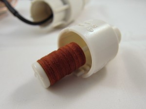
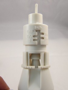
So how does this rain sensor work? It’s pretty simple. The sensor has two wires, which are normally connected to each other inside through a switch. The top of the sensor has a small chamber, which contains a string of sponge pads (see below). When it rains, the water will drip into the chamber and gets absorbed by the sponge pads. The pads will then expand and press against each other as well as the top of the chamber. When it expands to a certain point, the switch inside the sensor will be pressed down, disconnecting the two wires. The height of the chamber can be adjusted to control when the sensor is activated – in other words, the amount of rain that will activate the sensor. There are five options: 1/8, 1/4, 1/2, 3/4, and 1 inch.

Down below the chamber is an evaporation window. The size of the window controls how fast the absorbed water evaporates, thereby controlling the rain delay time. After the rain stops, the sponge pads will gradually shrink, and at some point the switch is released, thus the two wires are connected again. This is a very clever design because it’s purely mechanical, requires no power itself, and is easy to adjust. The downside is that you cannot set the delay time precisely – obviously the local humidity and temperature will affect the evaporation speed.

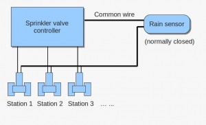
Once you figure out how it works, it’s very easy to connect it to OpenSprinkler. The diagram above shows the connection (Not sure where the ‘common wire’ is? Check out this diagram). Simply put, the sensor acts as a normally-closed switch placed on the common wire. When the sensor detects rain or freezing condition, it disconnects the common wire from the sprinkler valves. As is, it can work with almost any kind of sprinkler timer, without modifying the timer itself.

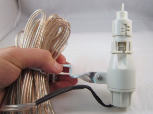
The sensor should be installed on the roof or next to the gutter. You need to run a wire from the sensor to your sprinkler timer. The sensor itself comes with a relatively long wire, so that shouldn’t be a problem. If you want, you can even get a wireless version at a slightly higher cost.

That’s it – if you need automatic rain delay control, this is an easy, inexpensive option you may consider.
OpenSprinkler Simple Web-based Control Program

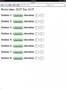
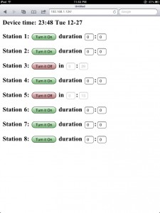
At times you may want a simple web-based interface to directly control each sprinkler valve, without having to set up a complex schedule. I’ve written the svc_simple_web program exactly for this purpose. To start, take a look at the web interface of this program:

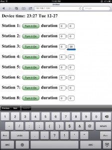
Quite simple, isn’t it. The top line shows the current time; underneath it is the list of eight sprinkler stations. Clicking a button will turn on the corresponding station, and clicking the same button again will turn it off. To make it a bit more useful, you can set a timer (i.e. duration) for each station. The duration is specified by the number of hours following by minutes (hh:mm). Once a station is turned on, the program will keep track of the running time and stop that station when the duration time is reached. Meanwhile, the webpage will display the remaining watering time. You can set an individual time for each station, say 30 minutes for station 3, and 15 minutes for station 5. Setting the duration to 0:0 means there is no time limit: once on, the station will only be turned off when you manually click on ‘Turn it Off’. This way, you can either manually control the stations, or set a timer for it.

If you are interested, feel free to try this program and let me know your comments. The program can be downloaded on the following page:

OpenSprinkler Download Page

Note that the software is now released in GitHub for the purpose of better version control. The code will be regularly updated. You can sign up for the RSS feed on the GitHub update history page, in order to track the updates.

OpenSprinkler ‘Weather’ Feature coming soon

This is a heads-up for the upcoming ‘weather’ feature in the OpenSprinkler software. It makes use of the Google Weather API to obtain current weather data in your local area. The Google Weather API returns data in XML format. Unfortunately the OpenSprinkler, which uses a small microcontroller, cannot directly handle the returned data. So what I had to do is to write a Python script that translates the XML data into something that’s much shorter and simpler, so that it can be processed by OpenSprinkler. I’ve put up the script on this website. You can try it by using the following url:

http://rayshobby.net/scripts/getweather.py?location=nyc

It returns a simple html page that’s well within a single Ethernet packet. One nice feature about using the Google API is that you can specify the location in a variety of different formats, such as zip code, city name, or sometimes abbreviated names like ‘nyc’. Feel free to give it a try. This script will be published later, so you can install it on any server you want.

Another feature is the weather forecasts. Right now I have no plan to use this information, but it may be useful for the future. You can get forecast data using:

http://rayshobby.net/scripts/getweather.py?location=nyc&forecast=1

It can return up to four days of forecasts.

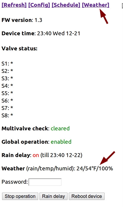
I’ve modified the Arduino code to periodically retrieve weather data from the server. The new OpenSprinkler webpage has the following changes:

Note the new ‘Weather’ link in the menu bar, and the weather information on the bottom, showing the current rain index, temperature, and humidity. The rain index indicates the heaviness of the rain, and translates to the rain delay duration. The program currently calculates the rain index from the weather description returned by the script. For example, ‘Rain’ or ‘Thunderstorm’ translates to a high rain index, while ‘Light Rain’ translates to a low rain index. In any case, this can be adjusted in software.
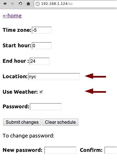
The configuration page has two added fields: the location, and the ‘Use Weather’ checkbox. Again, there is a variety of ways you can specify the ‘location’.

What I am currently working on is to update the software code to allow the control by weather data. The simplest way is to use the ‘rain index’ to control rain delay hours. More complicated strategy can be implemented by yourself. That’s the value of open-source and programmable gadgets!

OpenSprinkler Backup Battery Option

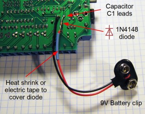
Matt asked about the option of having a backup battery for the OpenSprinkler, so I prepared a short blog article to show how it can be done. Basically, you just need to get a 9V battery (or any battery that can provide 6V or above voltage), connect the positive lead with a diode (such as 1N4148) in forward direction to the positive lead of C1 (100uF capacitor), and the battery’s negative lead to C1’s negative lead (which is ground). See pictures below for illustration. Make sure to use a heat shrink or electric tape to cover the diode after it’s soldered.

With the backup battery, the microcontroller (and hence the time) will keep running when there is power outage. Once the main power is back on and the Ethernet connection is available, the controller will be able to obtain more accurate time through NTP sync (the default setting is one sync per hour).

But there is a catch (as always!), which is: the controller draws a lot of current (~140mA), so with a standard 9V battery (the typical capacity of which is 560mAh) it can only last for about 4 hours.
The large current draw is mainly due to the Ethernet controller. One solution is to use a higher capacity battery (such as AA or Li-Poly). Another option is to put the Ethernet controller to sleep when it cannot get a connection. This can be done in software. In any case, there is now a temporary solution for battery backup, and a better option will be provided in the next hardware update.

OpenSprinkler v1.0 Known Issues Documented on the F.A.Q. Page

Thanks for everyone who ordered the initial batch of the OpenSprinkler controller. A couple of issues have been reported and documented on the F.A.Q. page. If you are learning to use the controller, be sure to check that page.

The most recent bug turned out to be caused by the Arduino’s shiftOut function (thanks Matt for discovering the problem initially). This bug has now been reported to the Arduino forum. The symptom is that whenever you open the sprinkler zones, station #8 always turns on, and will remain on even if you stop the controller’s operation. This is caused by the shiftOut function missing a rising edge for the shift register. You can simply re-program the microcontroller to fix this bug. Orders sent on or after Oct 23, 2011 have already included this bug fix.

Update on ‘How to control Orbit 62035 valve’

It has been a while since I updated my blog. Things have been quite crazy the past few months, but now I am back alive writing more blogs sparingly.

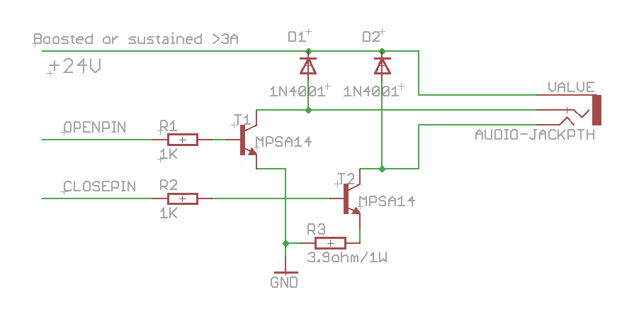
The first thing I want to share about is an update to my previous post that talked about how to control the Orbit 62035 valve. There have been a couple of missing pieces there which I would like to clarify. First, I found that a MOSFET cannot reliably control that valve. I am not sure why, but it may have to do with the on-state drain to source resistance. But using a MPSA14 (NPN darlington) works, and it requires a base current limiting resistor, so I’ve updated the schematic as below. Second, I was reminded that two kickback protecting diodes are needed to protect the transistor from the inductive current from the solenoid, so those are also added. These are the two main changes. The circuit below has been tested to work. Feel feel to leave comments.


Meet the Arduino WaterValveShield

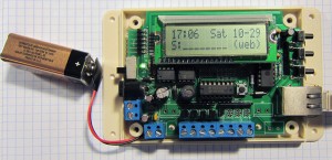
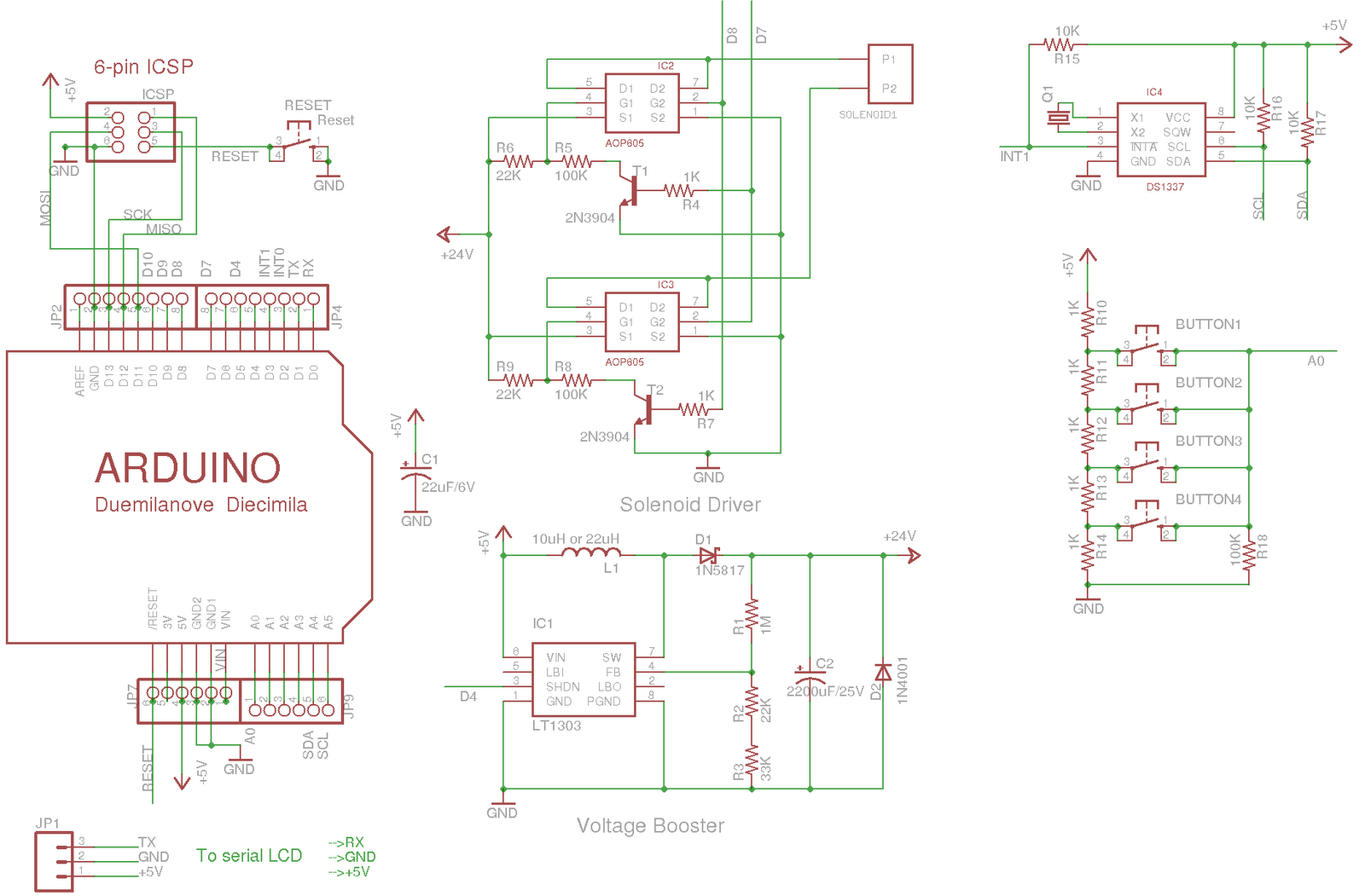
After finishing the previous minty water valve controller, I decided to make it an Arduino shield. This way, I can easily stack it onto other shields and extend its capability. I also added a few input buttons, and a DS1337 real-time clock, so that it can keep up with accurate time. Now the circuit has become much smaller, so I can’t produce it with home-made PCB any more(sadly…). Instead, I ordered professionally made PCBs from Laen, and here you are, meet the Arduino WaterValveShield!

PCB board:

Components soldered:

Close-up view:

Connected to a serial LCD display

The schematic:

You can download Eagle schematic and PCB design here. Feel free to use it and/or modify it, but be kind to give me some credit for it 🙂

Parts list with Mouser/Digi-key links: valve_shield_parts.zip 

As for sketch code, refer to my previous posts for code to control the valve and read input buttons. To interface with DS1337 RTC, I use this excellent RTC library.

Next steps:

How to control Orbit 62035 valve

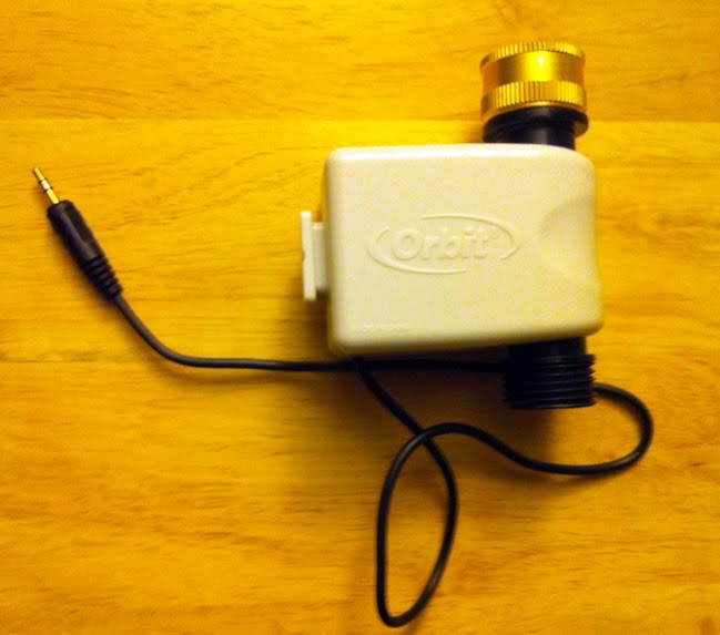
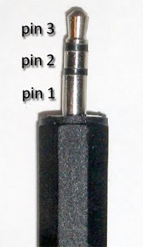
As an update to my previous post, I took a look at the Orbit 62035 valve, which works with the older Orbit’s yard watering system 62032. This valve is white colored, and has a standard 3-pin 3.5mm stereo audio plug.

To figure out how to control the valve, my initial guess is that the valve contains two coils, one opens the solenoid and one closes it. To verify this, I measured the resistance between the 3 pins of the plug. It turns out that pin 1 and 2 have a 4.5 ohm resistance, while pin 1 and 3 have a 0.9 ohm resistance. The 4.5 ohm resistance is reasonable, as it’s roughly the same with the Orbit 91592 valve that I used previously. But the 0.9 ohm resistance is strange — it clearly indicates a coil but the resistance seems too lower.

Having no other reference, I went ahead to apply voltage on the pins to see what would happen. Interestingly, applying +24v on pin 1 and 2 successfully opens the valve, but doing the same on pin 1 and 3 fails to close the valve. I tried everything I could to figure out what went wrong, but nothing came up. Out of luck, I decided to buy the full kit (62032) and reverse engineer the control unit a little bit. When I opened the control unit, I found that the entire circuit board is covered by a thick layer of water-resistant paste. This didn’t look good. However, I did notice several big resistors, each reading about 3.9 ohm. The size of the resistors seems to suggest that they are rated at 2W.

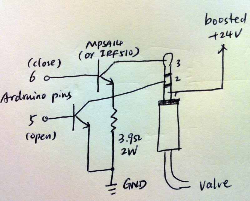
Given this finding, my suspicion is that applying +24v directly across pin 1 and 3 discharges the voltage too quickly, thus cannot close the solenoid properly. In fact, given the 0.9 ohm resistance, a momentary current of 26 Amp is produced, which sounded quite scary. Adding a 3.9 ohm resistor is probably used to limit the current, slowing down the voltage discharge. This actually helps to build the electromagnetic field in the solenoid, allowing it to close properly. The idea turns out to work like a breeze: I connected a 3.9 ohm resistor between pin 3 and ground, and this time the valve nicely closed. At this point, I’m pretty sure I’ve figured out how it works. 

You might wonder what the differences are between this valve with the Orbit 91592 valve. Here are my two cents:

Pros:
– 3.5mm stereo audio jack makes it easy to connect (in comparison, the 91592 valve requires custom connector)
– Pin 1 can remain connected to +24v, while grounding pin 2 or 3 is used to control the opening/closing of the valve. This simplifies the circuit design a lot. In fact, only two low-side drivers are needed to ground pin 2 or 3, which is much simper than h-bridge driver required by the 91592 valve.

Cons:
– Seems to be of its own kind on the market (my impression is that this is a discontinued product). Most other latching solenoids available on the market are similar to the 91592 valve. Fortunately Walmart still carries this product currently, but I don’t know how long it will last. 

Below is a sketched schematic when using this valve to replace the 91592 valve. As you can see, the circuit is much simpler than before. The driver can use either a darlington transistor (such as MPSA14), or an N-type MOSFET (such as IRF510).