- ESP8266 module and ESP8266 Toy are available for purchase at Rayshobby Store.
- ESPToy version 1.2 announced! Check out the announcement post here.
- Resources for Programming ESP8266 using Arduino
Content
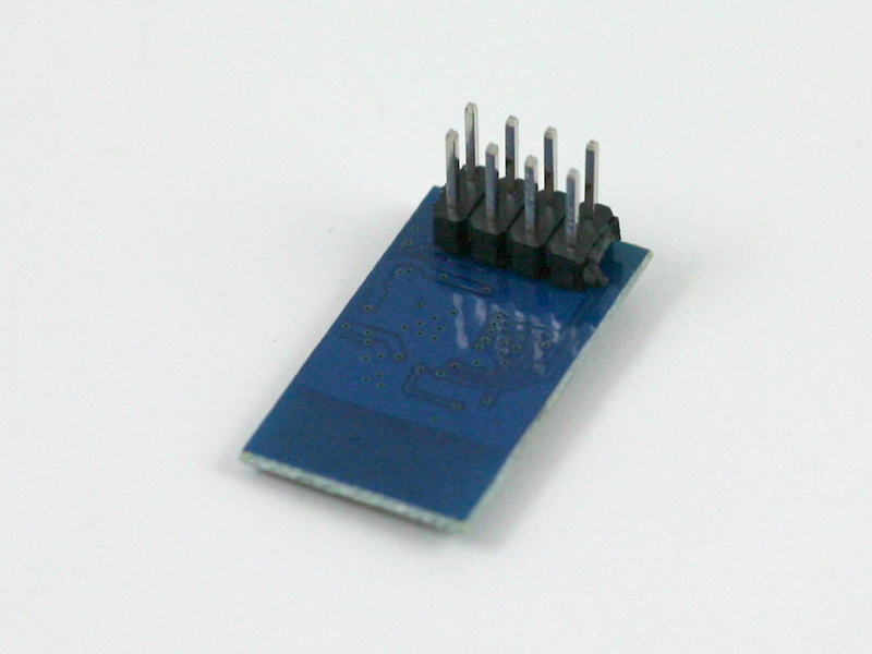
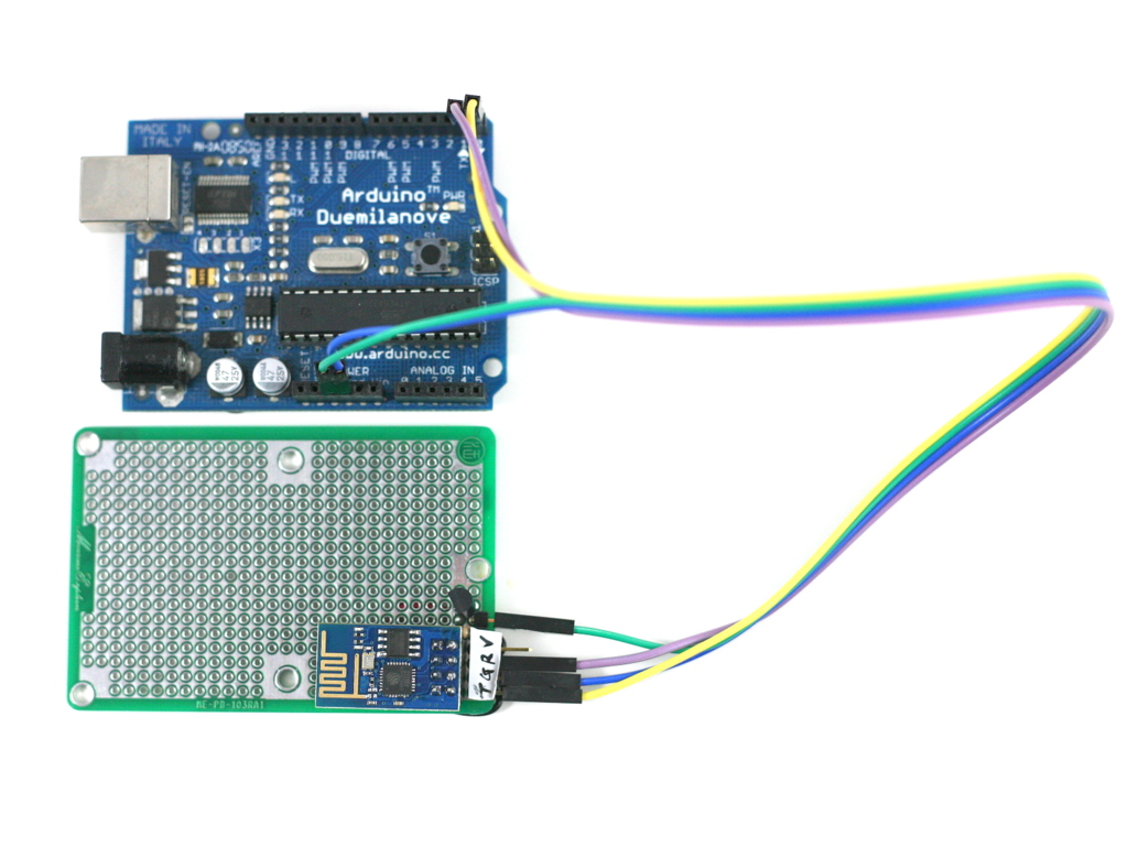
ESP8266 — a very low-cost and flexible Serial-to-WiFi module that has gained a lot of popularity recently. It allows any microcontroller to have WiFi capability by simply using serial communication. In a previous blog post, I demonstrated how to use ESP8266 combined with an Arduino to set up a very simple web server. This time I built a standalone gadget for prototyping called the ESP8266 Toy (or ESPToy for short). There is also a more serious web server demo in the end that shows how to serve HTML files from a SD card, and using JSON and AJAX to implement prettier web design.
You should also know that there has been a lot of on-going development for this module. For example, there is a Lua-based firmware for ESP8266, which is quite amazing. Also check out the community forum here.
As usual, a video demo first:
Original ESPToy 1.0/1.1: Youtube Video Link
ESP8266 module and ESP8266 Toy are available for purchase at Rayshobby Store.
Features
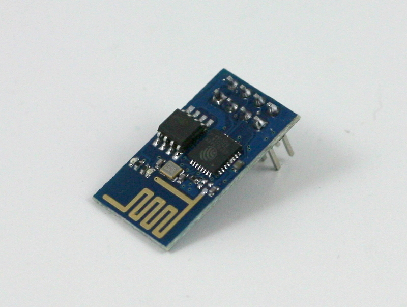
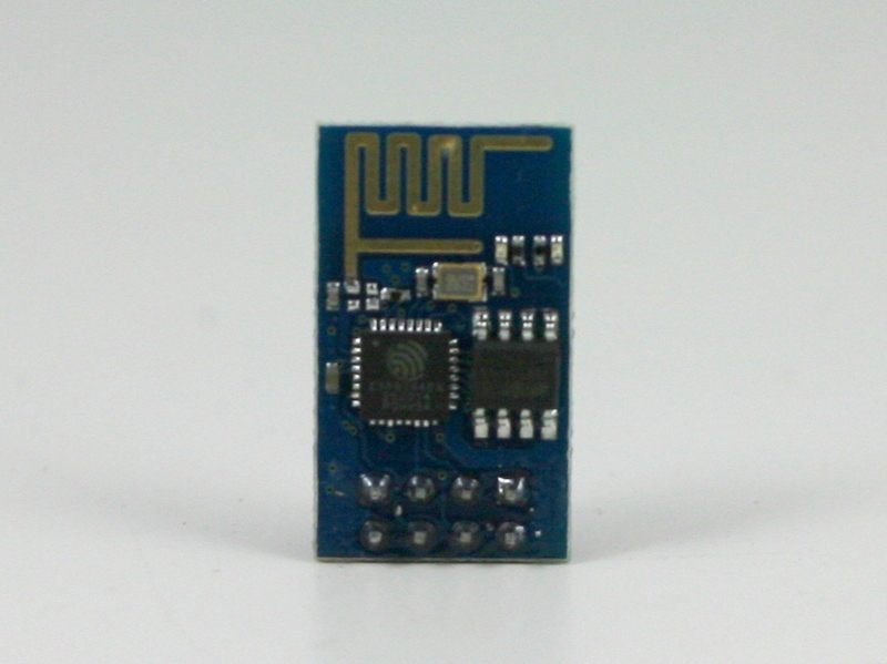
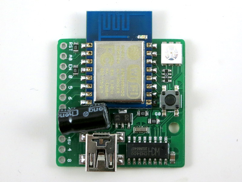
- ESP-12 SMD WiFi module, pre-flashed with Lua firmware and a startup demo script.
- 3.3V 250mA linear regulator.
- Programming using the on-board mini-USB port.
- One color (RGB) LED, one pushbutton (used as a general-purpose pushbutton as well as for re-flashing firmware)
- Additional pin headers for connecting external components and/or breadboard experiments.
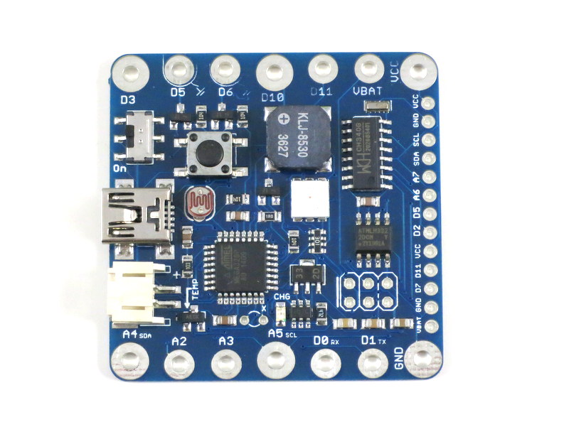
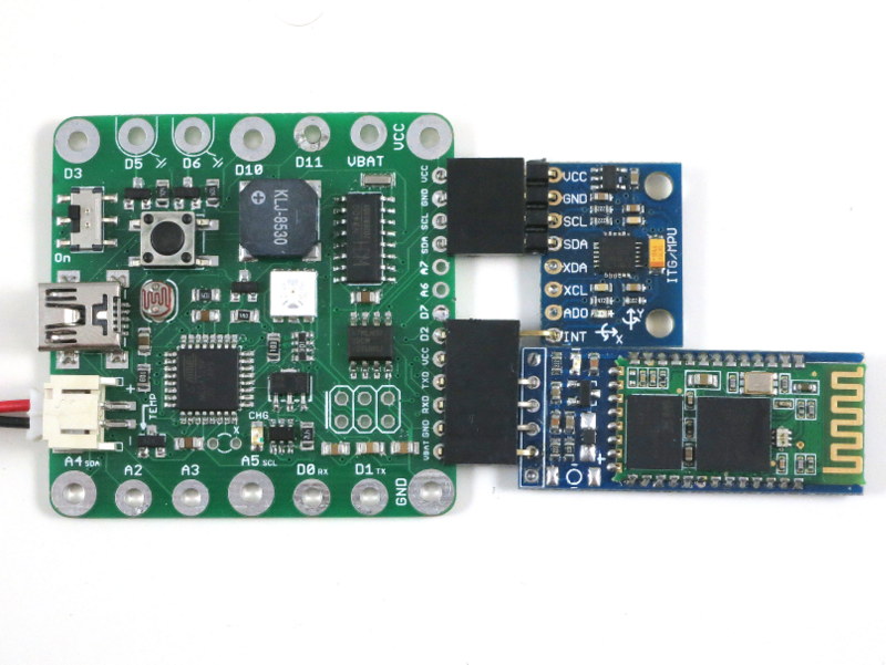
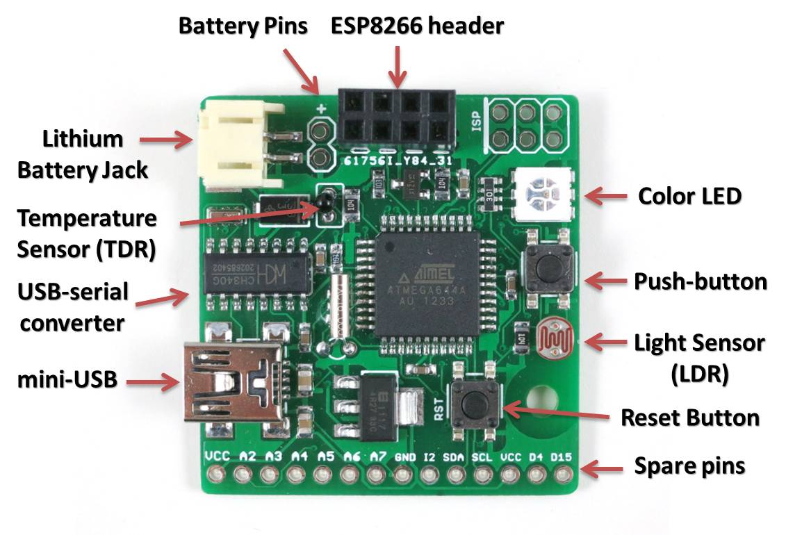
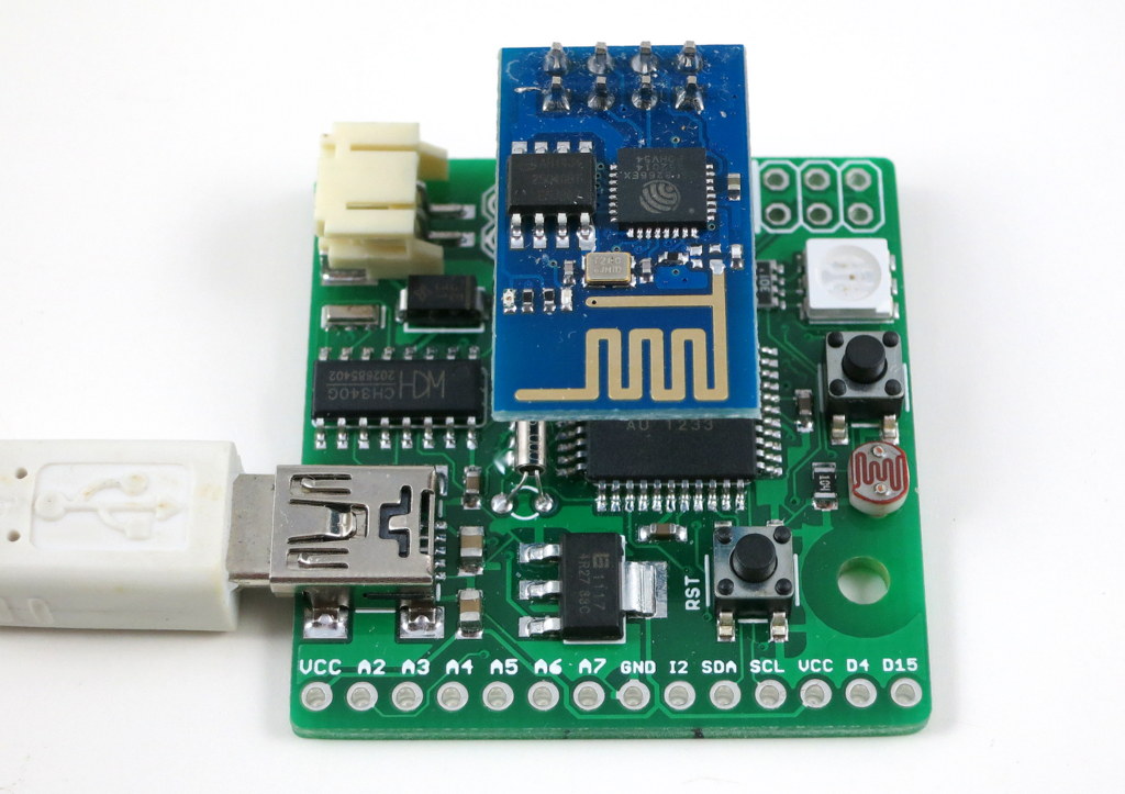
Original ESPToy v1.0/1.1 (retired)
- ATmega644 @ 3.3V, 16MHz, with CH340G USB-serial converter and Arduino bootloader.
- 3.3V 500mA linear regulator.
- Programming in Arduino using the on-board mini-USB port.
- One color (RGB) LED, one pushbutton, one reset button. (New on version 1.1: one additional button on ESP8266’s GPIO0 pin, useful for firmware upgrade)
- One light sensor (LDR), one temperature sensor (TDR).
- One 2×4 pin header to fit ESP8266.
- Additional pin headers for connecting external components and/or breadboard experiments.
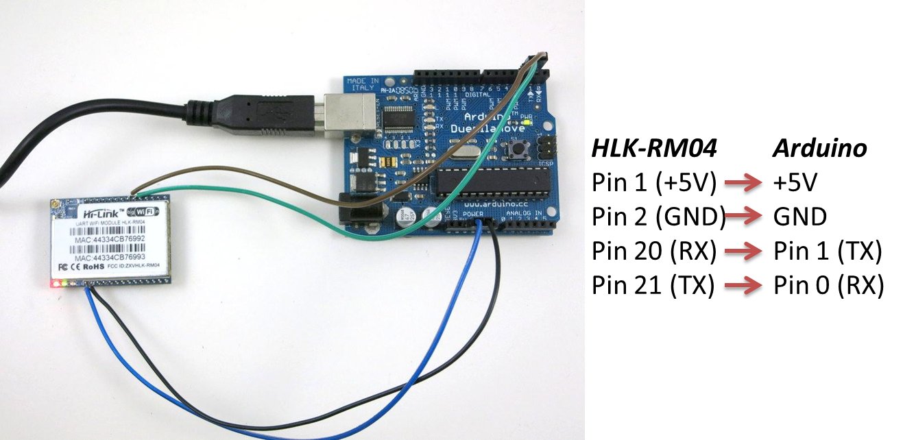
In essence, the ESPToy 1.0/1.1 is a 16MHz Arduino with some handy built-in components for easy prototyping with the ESP8266 WiFi module. Once programmed, the whole assembly can run on battery. There is also a power MOSFET on board to programmably control the power supplied to ESP. This allows you to cut off power to save battery life.
The reason I picked ATmega644 (instead of ATmega328) is that 644 has two hardware Serial interfaces. I am using one for the bootloader and USB communication, the other dedicated for WiFi. This is quite handy and allows you to use the fast baud rates. Also, 644 has twice as much memory as 328, so it’s suitable for building more complex projects.
Demos
As shown in the video above, I’ve written a few examples to demonstrate the basic features of the ESPToy:
To upload the demo Lua scripts to ESPToy 1.2, download and run the ESPlorer software. The Serial port baud rate is 9600 (default). You can open a demo script, click on ‘Save to ESP’ to save the script as a file to ESP’s internal flash memory space. The script will run right away after uploading. You can also click on ‘doFile’ to re-run the script.
- Start-up Demo: every ESPToy 1.2 is pre-flashed with a start-up demo. Plug in a mini-USB cable, the blue LED will blink and the WiFi module will start in access point mode, creating a WiFi network with SSID ESPToy-xx. The password is opendoor. Connect to this WiFi network, open a browser, and type in http://192.168.4.1. Use the sliders to change the LED color, and click on ‘Refresh Value’ to read button status and analog pin value.
- Hello ESPToy!: shows the Serial print function.
- Blink LED: shows digital pin write, and delay functions.
- Button Interrupt: shows how to set up interrupt on a digital pin.
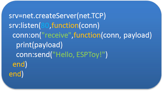
- Hello ESPToy Server: shows a simple HTTP web server.
Original ESPToy v1.0/1.1 (retired)
- SearchBaud: this comes handy if you forgot the correct baud rate of your ESP8266. It loops through the common baud rates, sends an empty AT command, the detects the correct baud rate by checking the result.
- SerialCommand: this demo allows you to send AT commands to ESP8266 through a Serial monitor. Use this demo to experiment with all the AT commands available for ESP8266.
- ScanNetwork: this demo starts the ESP8266 in AP mode, which creates a local WiFi network (the name is ESPxxxx). Use a smart phone or laptop to log onto this network, then open a browser and type in IP adddress 192.168.4.1. You will see a webpage with a list of detected WiFi networks. Type in the ssid and password of the target network, then click on Connect. The page will redirect in about 10 seconds to show the client IP address of the module on the target network. This is pretty standard approach to get your WiFi-enabled gadget to log on to your target network.
- WebServer: this is a simple web server demo. It serves a html webpage and uses JSON and AJAX to periodically display the analog pin values. The first two analog pins correspond to the light and temperature sensors respectively, so these two values will respond to light and temperature changes. There are also three sliders to set the color of the on-board LED. As I said before, the demo can run on battery, so this can be used as a WiFi-enabled color LED light. Thinking about a simplified version of the Philips Hue? Yup, this is a poor man’s version of that 🙂
- WebServer_SD: same as above, except this requires an external SD card slot, so that it can serve bigger and multiple html pages from files stored on the SD card.
Preparation
The ESPToy’s source code is available on Github. Check the README file therein to get started.
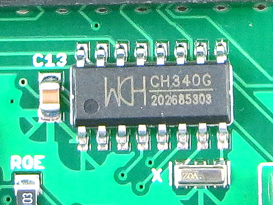
Serial Port and Driver:
ESPToy uses a CH340G USB-to-Serial converter. For:
- Windows 7, 8, 8.1 and Linux: no driver installation is needed.
- Windows XP: download and install driver http://raysfiles.com/drivers/ch341ser.exe
- Mac OS: download and install driver http://raysfiles.com/drivers/ch341ser_mac.zip
On Windows, the Serial Port name is COM? where ? is a number assigned to the USB-serial chip. On Linux, the Serial Port name is /dev/ttyUSB? where ? is a number. On Mac, the Serial Port name is tty.wchxxx.
Programming ESPToy 1.2
Instructions in this section are being re-organized. For now please refer to the ESPToy 1.2 instructions in this blog post.
Programming ESPToy 1.0/1.1 (retired)
Programming the ESPToy can be done through the Arduino IDE (tested with Arduino version 1.0.6). Because ATmega644 is not a board that appears in the stock Arduino, you will need to copy the atmega644 subfolder (from the hardware folder) to the corresponding hardware folder in your Arduino’s installation directory; same with the ESPToy subfolder (from the libraries folder).
Next, launch the Arduino IDE, select Tools->Board->ESPToy, and the correct Serial port from Tools->Serial Port (see below), then select a program from File->Examples->ESPToy, and finally click on Upload
ESPToy Arduino Library:
The RFToy Arduino library can be downloaded from: http://github.com/rayshobby/esptoy. You can either clone this Github repository, or download it as a zip: https://github.com/rayshobby/ESPToy/archive/master.zip
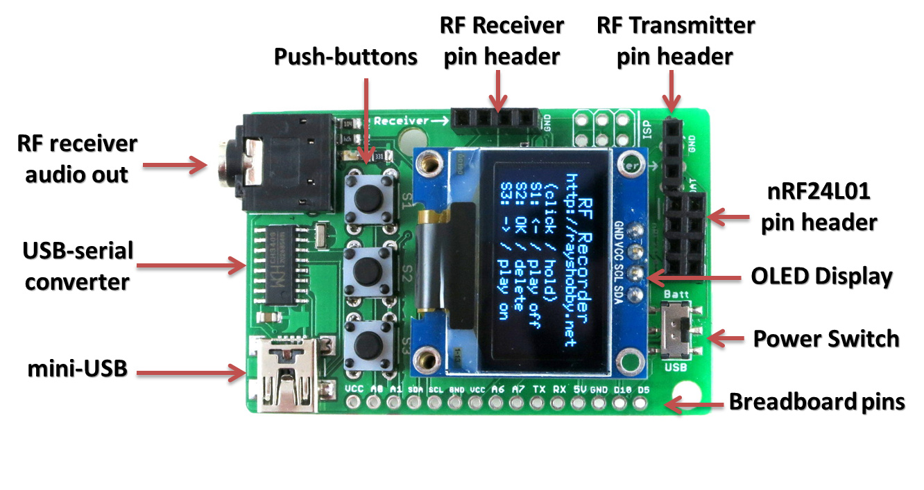
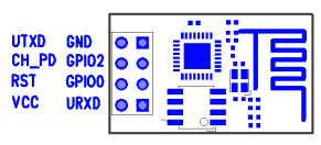
Pin Assignments:
- D0: ESP power (active LOW, pulled down by default)
- D3: push-button
- D12: red LED (pwm)
- D13: green LED (pwm)
- D14: blue LED (pwm)
- A0: light sensor (LDR)
- A1: temperature sensor (TDR)
- Serial: USB serial TX/RX
- Serial1: ESP8266 TX/RX
Spare Pins: D2 (INT2), D4, D15, A2, A3, A4, A5, A6, A7
Power Options:
ESPToy can be powered by USB or an external battery. There is a battery jack that fits a standard 3.7V lithium battery. In addition, there are two battery pins (next to the battery jack) — you can solder wires to connect a 3V AA/AAA battery pack. Note that the external AA/AAA battery should not exceed 3.6V (because it’s not regulated).
Flashing a New Firmware to ESP8266
Programming ESPtoy with Arduino: I strongly recommend you to learn to use Arduino to program ESPtoy, due to its flexibility and memory efficiency. While Lua firmware is easy for beginners, to write advanced programs, it’s much easer to use Arduino. Check the resources in this forum post.
On ESPToy 1.2 and 1.1: there is a pushbutton button (on version 1.1 it’s at the upper-left corner) — it’s connected to ESP8266’s hardware GPIO0 pin. If this button is pressed when powering up ESPToy, the ESP8266 will enter bootloading mode waiting for a new firmware. I recommend using the esptool python program to upload firmware, which is very easy to use. Specifically, in command line, run
./esptool.py write_flash 0x00000 xxxx.bin
where xxxx.bin is the firmware name.
On ESPToy 1.1, use the SerialCommand sketch to prepare ESPToy as a serial relay.
- The latest AT firmware can be found at: http://www.electrodragon.com/w/ESP8266#Firmware.
- The latest Lua firmware can be found at: https://github.com/nodemcu/nodemcu-firmware/tree/master/pre_build (when downloading a file from Github, click on the Raw link).
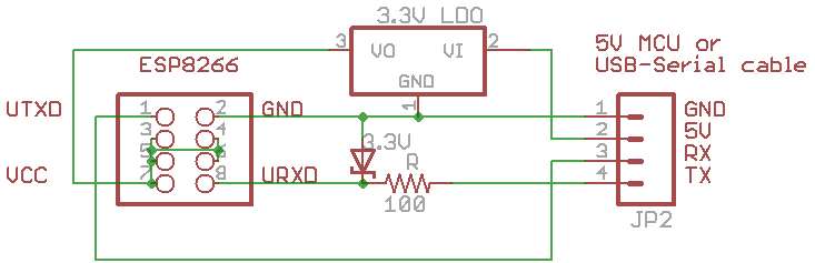
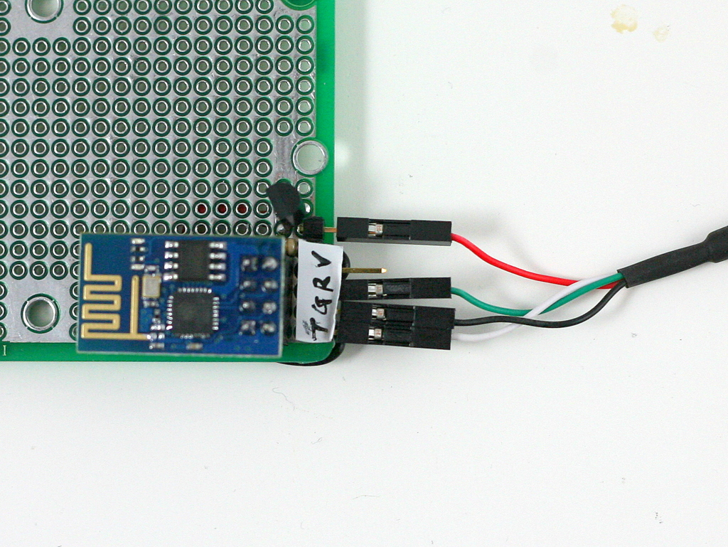
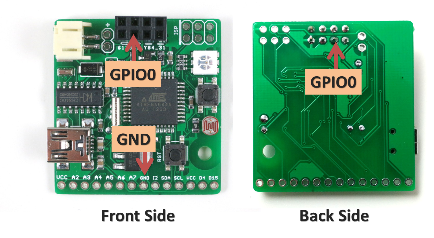
For ESPToy 1.0 (retired): to let ESP8266 enter bootloader, you need to solder a wire from ESP8266’s GPIO0 pin to ground. Specifically, if GPIO0 is pulled to ground, upon power-up ESP8266 will enter bootloader mode waiting for a new firmware from the Serial interface. In contrast, if GPIO0 is pulled up (to VCC), ESP8266 will boot into normal operation mode.
The picture below shows where the GPIO0 pin and a ground pin (any ground pin on the board should work). The wire should be soldered at the back of the circuit board. You can also connect a switch in series on the wire to easily switch between bootloader mode and normal mode.
Once this is done, you can flash the SerialCommand sketch to ESPToy, which will make it serve as a Serial relay. I recommend using the esptool python program to upload firmware, which is very easy to use. Specifically, in command line, run
./esptool.py write_flash 0x00000 xxxx.bin
where xxxx.bin is the firmware name.
- The latest AT firmware can be found at: http://www.electrodragon.com/w/ESP8266#Firmware.
- The latest Lua firmware can be found at: https://github.com/nodemcu/nodemcu-firmware/tree/master/pre_build (when downloading a file from Github, click on the Raw link).