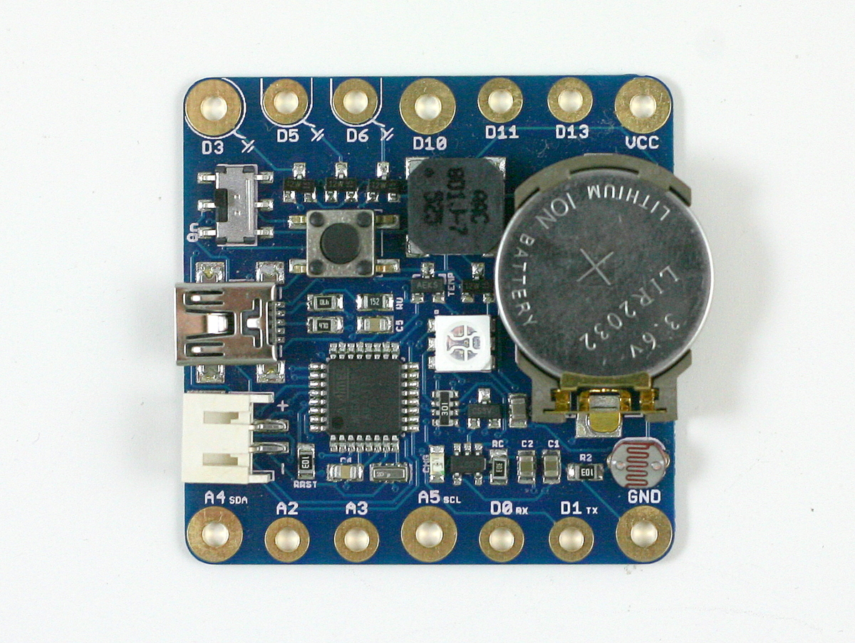
This is a long delayed post. I am glad I finally finished making a video for it, and it’s time to introduce SquareWear 2.0 — an open-source, wearable Arduino microcontroller board. At heart, SqureWear 2.0 is an Arduino running at 3.3V and 12MHz. It has built-in mini-USB port for uploading programs, charging lithium batteries, and creating a serial communication channel. It comes with a lot of useful built-in components, such as a color LED, a general-purpose push-button, a buzzer (yup, you can make it sing a tune), light sensor, temperature sensor, three MOSFETs (to drive high-current load). Even better, it has a built-in rechargeable lithium coin battery (you heard it right: rechargeable coin battery!), so you can power your project right away without requiring external power supply. Every time you plug in the mini-USB cable, it charges the coin battery automatically. Better still, if you want a beefier battery, you can plug in an external lithium battery through the on-board battery jack. The built-in lithium charger can charge external battery as well. Overall SquareWear 2.0 packs a lot of useful features on a 1.7″ x 1.7″ board. It’s great for wearable electronic projects as well as general-purpose microcontroller projects. Below is a summary of built-in components:
- ATmega328 running at 3.3V, 12MHz.
- MCP1700 3.3V / 250mA LOD.
- MCP73831 lithium charging chip (configured to charge at 35mA).
- MCP9700 temperature sensor.
- 10K photo-resistor.
- Four 2N7002 MOSFETs.
- 5050 color LED.
- 8.5mm SMT buzzer.
- 6mm SMT tactile button.
- Charging indicator LED.
- LIR2032 rechargeable lithium coin battery (45mAh capacity).
- 2.0mm JST connector for external lithium battery.
- SMT mini-USB port, and power switch.

Last year around this time I released SqureWear 1.1, which is based on Microchip’s 18F14K50 microcontroller. It’s pretty neat, but over time I’ve received quite a few requests to develop a similar board based on the Arduino. This inspired me to work on SquareWear 2.0. Many design choices, including components I selected to put on board, were based on feedback and experience at various wearable electronics workshops I organized.
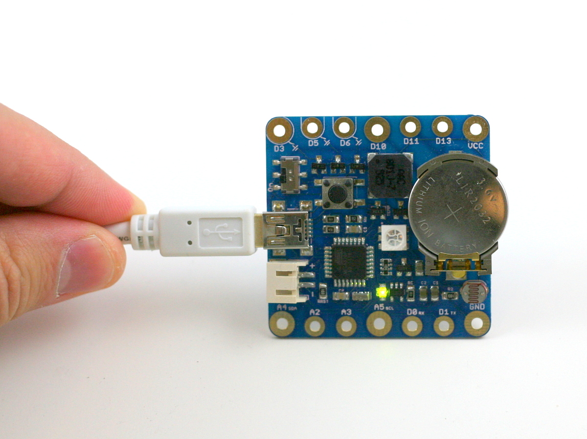
With SquareWear 2.0, programming is now done through the Arduino software. You can make use of thousands of available Arduino libraries to help build your project. Similar to the standard Arduino, it is based on a ATmega328 microcontroller. However, SquareWear does not have a separate USB-to-serial chip. Instead, it simulates USB functionality all in software, using the V-USB library. It has a USBasp bootloader, and can perform serial communication through USB. It can also simulate a mouse, a keyboard, or other human interface devices (see V-USB example projects). While software-based USB is not that fast, it really helps reduce the cost and size of the board by having one chip to carry out all the tasks. That’s why we can offer SquareWear 2.0, with all the aforementioned components and features, at a very competitive price.
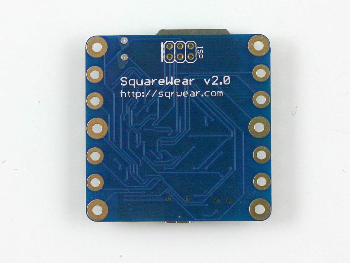
The bootloader is based on Frank Zhao’s USnoobie project. To enter programming mode, press and hole the on-board tactile button, then turn on power. This will allow the microcontroller to bootload as a USBasp programmer, which is supported by Arduino. On Linux and Mac, you don’t need to install any driver; on Windows, you need to install the USBasp driver (come on, Microsoft!), which is included in the SqureWear software package. The board has internal assignments for the following pins:
- D2/D7: USB D-/D+.
- D4: tactile button.
- D8/D12/D13: LED red/green/blue channel.
- D9: buzzer.
- A0/A1: light/temperature sensor.
The other pins are all mapped out to sewable pin pads with large holes. You can either stitch conductive threads through the pins, or solder wires directly onto the pins, or solder snaps to make it easy for quickly attaching or detaching the board from fabric.

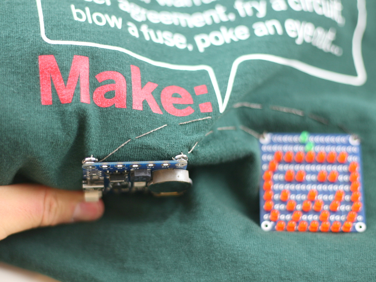
I should mention that pins D3, D5, D6 are internally connected to n-channel MOSFETs and these pins are suitable for driving high-current load (up to 250mA each pin). This is very useful if you want to switch a large number of parallel LEDs, a motor, a muscle wire, a heat wire etc. You can even combine two or three of them together to drive higher current. If you are familiar with Arduino, you should know that these three pins also support hardware PWM, so you can use them to control the brightness of LEDs, the speed of a motor etc. Technically I call them ‘power sink pins’ because unlike a standard output pin, they can only connect or disconnect a component from ground (sink). So the right way to use them is by connecting the positive wire of your component to Vcc (or external power), and the negative wire to one of the MOSFET pins.
Anyways, I want to keep this post short, so I will leave you to find more details in the video tutorial above, and the user manual in the software package. If you are interested in buying SquareWear 2.0, it’s available for purchase at the Rayshobby Shop. Feel free to leave comments below, or on the forum. Thanks!