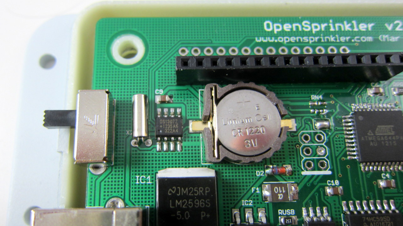
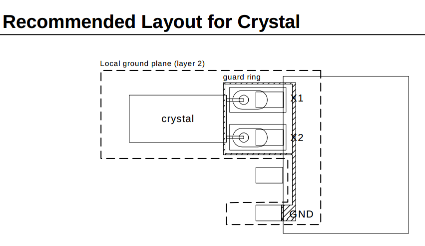
Recently a random crashing issue has surfaced on the forum regarding some of the OpenSprinkler 2.0 development boards that we sent out a few weeks ago. The background is that we have started shipping a development version of 2.0 for any recent order of the assembled OpenSprinkler. The symptom is that some of the units started crashing and losing network connection, and this seems to be always correlated with the timing running crazy off the charts. Initially I thought this issue may have been caused by a bad RTC crystal, which leads to incorrect timing, and which in turn causes the controller to get stuck. Then at some point I realized all the problematic cases happened on a particular PCB version dated Nov 2012. This helped me narrow down the search range. After a thorough comparison to the more recent version, I discovered that the problem is actually caused by a noise coupling issue with DS1307 RTC. Specifically, according to the datasheet (right image below), the region around traces between the 32.768kHz crystal and DS1307 should be shielded by a ground trace. If this is not implemented, the crystal may pick up noise from nearby traces and cause the clock to run significantly off the charts. When I designed OpenSprinkler PCBs, I had not paid attention to this recommended layout at all. Jeese, why did’t I read the datasheet carefully!
After discovering the issue, I panicked a little bit. Since I didn’t know about the issue previously, and there are hundreds of boards in production at SeeedStudios, am I screwed? It turns out that the situation is not as bad as I thought. First of all, I usually add a ground plane to fill the empty spaces between traces. As a result, on most PCB versions, there is indeed a ground plane around the traces from the crystal to the RTC. Below are examples of the traces on OpenSprinkler 1.4s, the more recent version 2.0, and the version in production at SeeedStudios:

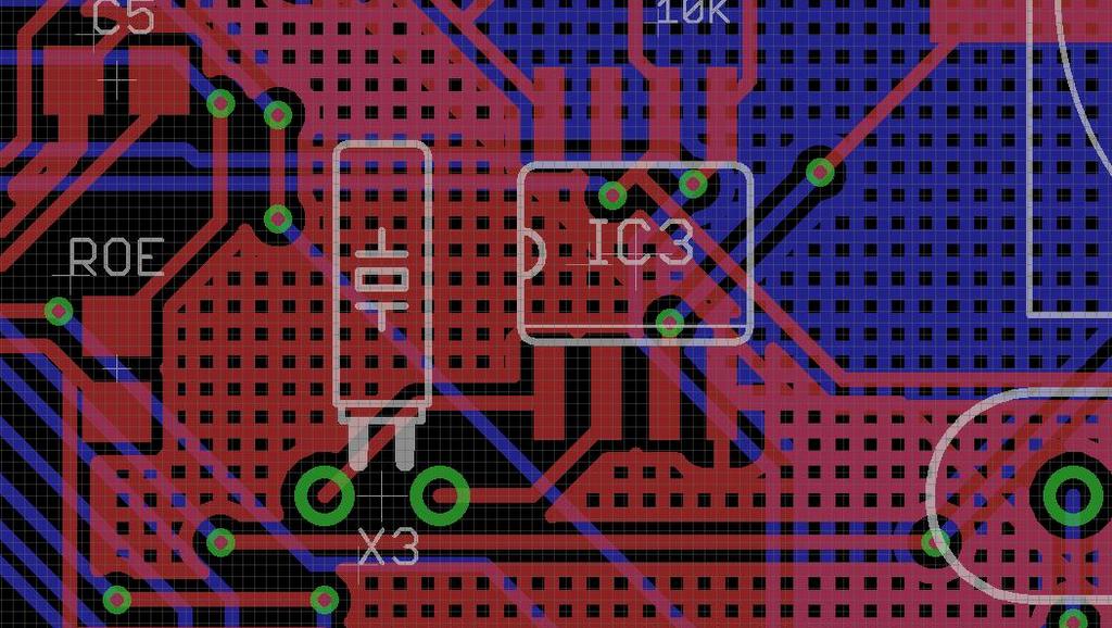
Although they don’t match the recommended layout exactly, they are pretty good at shielding the crystal pins from picking up noise. You know, I have always questioned about those ground planes and wondered whether it’s worth my effort of adding them. Well, in this case it did save me from potentially deep trouble.
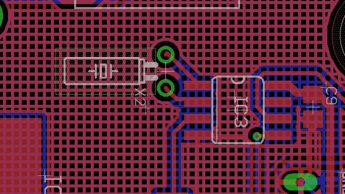
Now, in comparison, on the Nov 2012 version of 2.0, the ground plane is missing around that region (probably because there is not enough space between the traces to allow a ground plane). As a result, here is the PCB image:
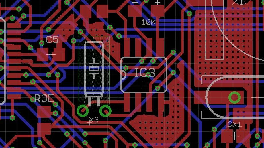
Not only it is missing the ground plane in that region, but also there are all kinds of signal traces nearby, which makes is extra easy to pick up noise. This is bad, bad, bad. Now, that being said, even with the careless design, it’s not like you are guaranteed to have the problem. It more of a reliability thing: it increase the chance of noise coupling, but in many cases the issue probably doesn’t show up. In fact I was trying to reproduce the problem today on a particular PCB version that has no ground plane. After testing 8 of these, one showed a problem of extremely fast clock (5x faster than normal). And it turned out that I forgot to cut the crystal leads, which make them act like antenna to happily pick up noise. After cutting the leads, the clock went back to normal speed. This probably explains why the problem didn’t surface earlier even though I have never paid attention to the PCB trace around RTC previously.
The DIY version 1.42u is also missing the ground traces around that region. So I won’t be surprised if users have encountered a clock speed problem (although so far I have not received any report of it). In case this happens, an easy thing to try is to re-solder the 32.768kHz crystal and try to push it down to the PCB holes as much as you can. This will help reduce the length of the crystal pins and in turn reduce the chance of picking up noise. Another possibility is to simply solder the crystal directly onto the IC pins,
So overall this is a very valuable learning experience for me. I am grateful to those who reported the issue on the forum, and helped me figure out the problem as quickly as I can. There are about 10 of those Nov 2012 assembled boards out there, and I am happy to replace them for free. With that, it’s now time for me to revisit the datasheets. Never overlook them again!