The AASaver kit is now out of stock. In one day I’ve received about 92 orders, pretty crazy 🙂 I’ve placed another order of PCBs, and expect to have the kit back in stock in about three weeks. You can sign up to receive email notifications here: http://eepurl.com/jBK15, or alternatively, subscribe to my blog RSS Feed.
AASaver kit is out there and selling fast
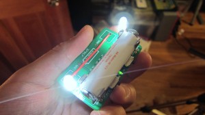
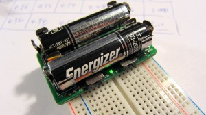
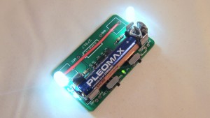
What is AASaver? Well, simply speaking, it’s a small voltage booster that can bump the voltages on your AA batteries to 5V or 3.3V, which you can use to power flashlight LEDs or breadboard circuits. It has some nice features, including on-board flashlight LEDs, voltage selection switch, power switch, and breadboard pin headers. I like it and I find it really useful. It is available for purchase in my online shop. Check out the full product details and a video demo on the product page:
AASaver just got posted on Hack A Day yesterday afternoon. Thanks for the publicity (Hack A Day is awesome!), orders are pouring in! The version without LEDs is already out of stock. I have placed a batch of orders and it should be back in stock in about 3 weeks. If you want to get notified when it’s back in stock, sign up for the AASaver stock notification list, or simply sign up for my blog RSS feed.
Using Rain/Freeze Sensor with OpenSprinkler
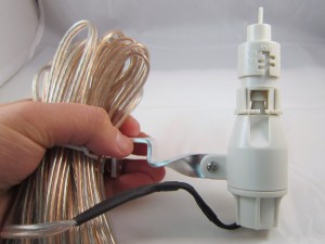
Rain/freeze sensors are useful for detecting rain or freeze conditions, and delays or stops watering accordingly. There are many types of rain sensors on the market. Recently I tried out this Orbit 57069 rain/freeze sensor. It’s very easy to connect to OpenSprinkler, and works quite well. The rain delay time can be easily adjusted by setting the water evaporation speed.
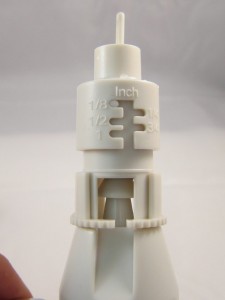
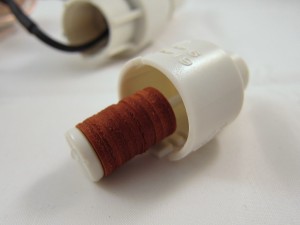
So how does this rain sensor work? It’s pretty simple. The sensor has two wires, which are normally connected to each other inside through a switch. The top of the sensor has a small chamber, which contains a string of sponge pads (see below). When it rains, the water will drip into the chamber and gets absorbed by the sponge pads. The pads will then expand and press against each other as well as the top of the chamber. When it expands to a certain point, the switch inside the sensor will be pressed down, disconnecting the two wires. The height of the chamber can be adjusted to control when the sensor is activated – in other words, the amount of rain that will activate the sensor. There are five options: 1/8, 1/4, 1/2, 3/4, and 1 inch.
Down below the chamber is an evaporation window. The size of the window controls how fast the absorbed water evaporates, thereby controlling the rain delay time. After the rain stops, the sponge pads will gradually shrink, and at some point the switch is released, thus the two wires are connected again. This is a very clever design because it’s purely mechanical, requires no power itself, and is easy to adjust. The downside is that you cannot set the delay time precisely – obviously the local humidity and temperature will affect the evaporation speed.
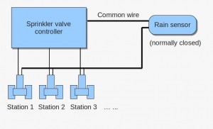
Once you figure out how it works, it’s very easy to connect it to OpenSprinkler. The diagram above shows the connection (Not sure where the ‘common wire’ is? Check out this diagram). Simply put, the sensor acts as a normally-closed switch placed on the common wire. When the sensor detects rain or freezing condition, it disconnects the common wire from the sprinkler valves. As is, it can work with almost any kind of sprinkler timer, without modifying the timer itself.
The sensor should be installed on the roof or next to the gutter. You need to run a wire from the sensor to your sprinkler timer. The sensor itself comes with a relatively long wire, so that shouldn’t be a problem. If you want, you can even get a wireless version at a slightly higher cost.
That’s it – if you need automatic rain delay control, this is an easy, inexpensive option you may consider.
Review of Microchip PICkit 2
Recently I was fortunate to receive a Microchip PICkit 2 from Newark.com to write a review on. I was very excited to get it because I have always wanted to learn about PIC microcontrollers. Why? Well, so far I have been quite experienced with Atmel’s AVR family chips, thanks to the Arduino that first got me into electronics. But it’s time to try something new in a new year 🙂 PICs offer several nice appeals including their product variety and functionality (e.g. support for USB, Ethernet, touch sensing etc.) and they have very competitive pricing. I know there are tons of debates about AVRs vs. PICs online. For now I am going to put them aside and make my own comparisons later after I get a good grip of both.
First Impression
PICkit 2 is a very popular tool for programming and debugging Microchip’s PIC microcontrollers. If you want to learn PIC programming, you almost certainly should get one. With the latest device file, it can support most PICs available on the market (although for some of the newer ones it only supports programming and not debugging). Microchip has an updated version — PICkit 3 which supports everything, but I prefer PICkit 2 because it’s cheaper ($34.99) and provides everything I need.
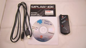
The package (product no. PG164120) contains the programmer itself, two CDs, and a USB cable. The programmer looks very compact. It has a USB port (as well as a key ring) on the top, a red button and three LEDs (power, target, and busy) on the front, and the 6-pin ICSP (In-Circuit Serial Programming) port on the bottom.
 |
 |
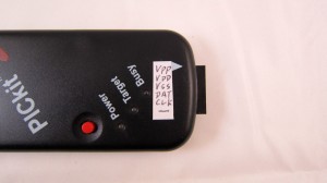
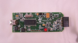
Since I am new to the ICSP pins and can easily get myself confused with the AVR’s ISP pins, I made a small label with all the pin names and attached it to the programmer. This way I will never forget the pins when prototyping circuits! The 6 pins are: Vpp, Vdd, Vss, ICSP-Data, ICSP-Clock, and the last pin is unused. Among them, Vpp can provide +12v for high-voltage programming, and Vdd/Vss can supply 5V or 3.3V to power your circuit, which is very convenient. The picture on the right below shows the circuit inside the programmer. It is based on a PIC18F2550 MCU.
 |
|
At this point I have to say that I like this programmer much better than AVR’s comparable programmer at the same price. Why?
- I like how the ICSP pins are all on one line. This makes it easy for breadboard experiments as it only needs a 1×6 pin header. In comparison, AVR’s ISP programmer requires a 2×3 pin header, which is always a pain for setting up on breadboard.
- It can do high-voltage programming, which means if I somehow messed up with the fuse settings I don’t have to panic. In comparison, AVR’s ISP programmer doesn’t do this (unless if you get a more expensive model). I remember the horrible experience when I first programmed my ATMega328 with wrong fuse values, I had to spend a whole day searching for solutions. Eventually I made a high-voltage rescue circuit and fixed the problem. But what a pain!
- It can provide power (anywhere from 2.5V to 5V) to your circuit.
- Probably the most valuable of all: it is a programmer and a debugger. You can use it for in-circuit debugging too! How nice! For AVRs, the comparable product would be quite a bit more expensive.
So overall, I am really glad to find out that this small and inexpensive programmer packs a lot of nice features in it.
Software Setup
Next I will try to write my first PIC program. There are basically two pieces of software to install: the MPLAB (version 8.6) which is the programming IDE, and the PICkit 2 standalone program (version 2.61). They are in the attached CDs, but you can also download them online at Microchip’s product website.
The MPLAB integrates everything you need: programming environment, compiler, uploader, and debugger. However, it turns out that it won’t support some of the newer chips (such as the one I got) if you are using PICkit 2. That means you can compile the program but won’t be able to upload it to the chip. The upgraded version PICkit 3 can handle all chips, but I don’t have it! Fortunately, PICkit 2 has a standalone program to work with the newer chips. Be sure to download the latest Device File from that website.
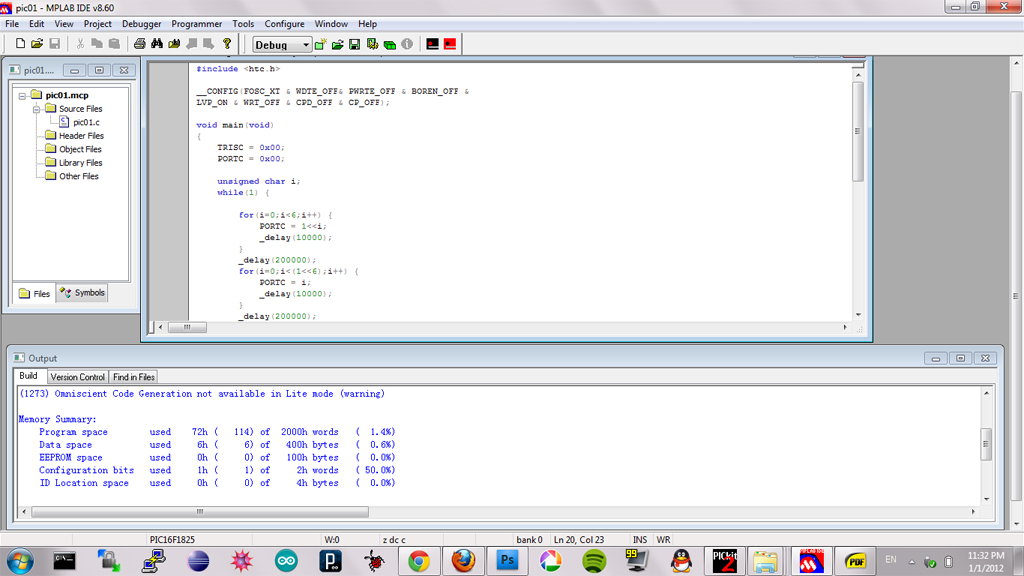
To write a program, you can either use assembly language or use C. I am going with C since I don’t know how to accomplish even a relatively simple program in assembly language. It makes my head blow… Anyway, MPLAB comes with a free HI-TECH C compiler (PICC light version). You can follow the ‘Quick Start’ tutorial, available in the compiler’s installation folder to easily write your first ‘Hello World’ (i.e. flashing LED) program. Here is a snapshot of mine:
The ‘Config’ bits are a bit confusing to me at first. But a read of the microcontroller’s datasheet will make everything clear. These are similar to the fuse settings in the AVRs. The main difference is that here you write the bit settings directly in the program, whereas AVRs separate the program with the fuse settings.
“Hello World” Experiment
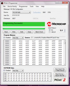
For my first experiment, I picked the PIC16F1825 microcontroller. It has 14KB program flash, 1KB RAM, 256B EEPROM, USART, 12 I/O pins, and it costs only $1.50. I thought I made a good choice. Unfortunately soon I found a small issue, which is MPLAB does not fully support this microcontroller if you are using PICkit 2. You can still write and compile a program, but you can’t upload or debug the program (these are only available with PICkit 3). Fortunately, the PICkit 2 standalone program can still work with it. So the solution is to write and compile the program in MPLAB, and use the standalone program to upload:
 |
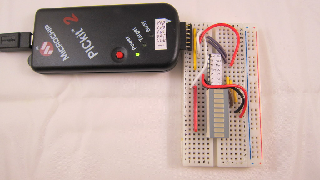 |
I made a simple testing circuit, consisting of the microcontroller, a 1×6 ICSP pin header, an LED bar graph and a resistor network. The goal is to, as we always do, flash some LEDs 🙂 The circuit is very easy to implement on a breadboard (see photo above). I basically started by connecting the 6 relevant pins to the ICSP pin header, then all port C pins (C0 through C5) to the LED bar graph, and finally the resistor network. Note that I also attached pin name labels to the microcontroller. In addition to the standard pin names (like A0, A1, C0, C1…), I especially marked the ICSP pins (VPP, ICSP-DAT, and ICSP-CLK). This makes it really easy to connect wires without having to look back again and again at the datasheet.
Upload a program: This is straightforward. First compile the program in MPLAB, then switch to the standalone program, import the compiled HEX file, and click on ‘Write’. The LEDs on the programmer will flash and after a few seconds it’s done.
Power the circuit: As I said earlier, the programmer can supply VDD anywhere between +2.5V to +5V. Note the checkbox for VDD ‘On’ and the voltage input box in the GUI above. Once you enable VDD, the Target LED on the programmer will light up, and the circuit will immediately start running. Voila, my ‘Hello World’ experiment is now complete!
Programming in Linux
I’ve also tried using the programmer in Linux (Ubuntu 11.04). First, MPLAB software installs and works just fine with Wine. Other than the GUI being a bit ugly, the software seems to be fully functional. Second, there is a tool called PK2CMD from Microchip website that works with PICkit2. You can use it to upload a compiled program to your microcontroller. Probably the only missing feature is debugging — there doesn’t seem to be a way to enable debugging in Linux. Well, you can always using MPLAB’s simulator to do software-based debugging. But if you definitely need hardware-based debugging, you can install Windows as a virtual OS in Linux. This way, all features of PICkit2 will be enabled.
Conclusion
So far my first experience with the PICkit 2 programmer has been very positive. It’s small, inexpensive, feature-rich, and relatively easy to use. I highly recommend it. In fact, if you are planning to learn PIC programming, I suggest getting this kit soon. Why? I’ve read from online websites that Microchip is discontinuing this product in favor of the newer PICkit 3, which is pricier and has actually received some negative comments (search for David Jones EEVblog PICkit 3 and you will find out). So before PICkit 2 runs out, go and grab one for yourself!
Resource Links
- Product page of PICkit 2 on Newark.com (Newark is the trade name of Farnell in the US, or Element14 in Asia Pacific).
- Microchip’s MPLAB IDE and PICkit 2 software.
- HI-TECH C compiler for PIC10/12/16 MCUs and PIC18 MCUs (the lite versions are all free).
- Alternatively, MPLAB C compilers for PIC18 or PIC24 series MCUs.
Finally, there are a few things I am yet to try, and I have put them on my todo list:
- Try the debugging feature.
- Program USB — I’ve already got a PIC that has built-in USB support. There are many PICs that have built-in USB and are in DIP package, great for breadboard prototyping.
- Try USB bootloader.
OpenSprinkler Simple Web-based Control Program
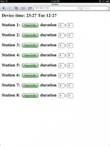
At times you may want a simple web-based interface to directly control each sprinkler valve, without having to set up a complex schedule. I’ve written the svc_simple_web program exactly for this purpose. To start, take a look at the web interface of this program:
 |
 |
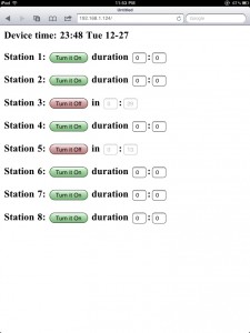 |
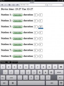
Quite simple, isn’t it. The top line shows the current time; underneath it is the list of eight sprinkler stations. Clicking a button will turn on the corresponding station, and clicking the same button again will turn it off. To make it a bit more useful, you can set a timer (i.e. duration) for each station. The duration is specified by the number of hours following by minutes (hh:mm). Once a station is turned on, the program will keep track of the running time and stop that station when the duration time is reached. Meanwhile, the webpage will display the remaining watering time. You can set an individual time for each station, say 30 minutes for station 3, and 15 minutes for station 5. Setting the duration to 0:0 means there is no time limit: once on, the station will only be turned off when you manually click on ‘Turn it Off’. This way, you can either manually control the stations, or set a timer for it.
If you are interested, feel free to try this program and let me know your comments. The program can be downloaded on the following page:
Note that the software is now released in GitHub for the purpose of better version control. The code will be regularly updated. You can sign up for the RSS feed on the GitHub update history page, in order to track the updates.
OpenSprinkler ‘Weather’ Feature coming soon
This is a heads-up for the upcoming ‘weather’ feature in the OpenSprinkler software. It makes use of the Google Weather API to obtain current weather data in your local area. The Google Weather API returns data in XML format. Unfortunately the OpenSprinkler, which uses a small microcontroller, cannot directly handle the returned data. So what I had to do is to write a Python script that translates the XML data into something that’s much shorter and simpler, so that it can be processed by OpenSprinkler. I’ve put up the script on this website. You can try it by using the following url:
http://rayshobby.net/scripts/getweather.py?location=nyc
It returns a simple html page that’s well within a single Ethernet packet. One nice feature about using the Google API is that you can specify the location in a variety of different formats, such as zip code, city name, or sometimes abbreviated names like ‘nyc’. Feel free to give it a try. This script will be published later, so you can install it on any server you want.
Another feature is the weather forecasts. Right now I have no plan to use this information, but it may be useful for the future. You can get forecast data using:
http://rayshobby.net/scripts/getweather.py?location=nyc&forecast=1
It can return up to four days of forecasts.
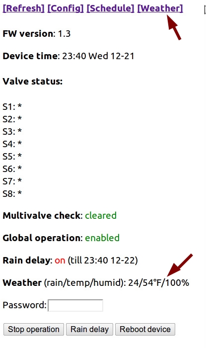
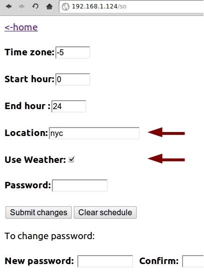
I’ve modified the Arduino code to periodically retrieve weather data from the server. The new OpenSprinkler webpage has the following changes:
What I am currently working on is to update the software code to allow the control by weather data. The simplest way is to use the ‘rain index’ to control rain delay hours. More complicated strategy can be implemented by yourself. That’s the value of open-source and programmable gadgets!
Learn to Make Solder Paste Stencils
I’ve had some rudimentary experience with surface mount (SMT) soldering in the past. The method I learned basically involves squeezing out solder paste from a syringe onto the PCB, placing the components, and then using a hot skillet to reflow. It’s pretty easy to learn. But if I want to produce assembled PCBs in large quantity, the syringe method is not going to work well. Instead, I need to use a solder paste stencil to quickly apply solder paste onto PCBs.
Solder paste stencils (aka SMT stencils) are expensive if you want to order them. Even a small piece would cost $30-$40, and that’s often the price for just one. I wanted to learn how to make stencils myself, so I can produce them quickly, and as many as I want. I don’t own a laser cutter. Fortunately, I found this really clever method from Instructables. After trying it a couple times, I’ve got a good grip of it. Below I document the process with pictures. The method is essentially based on the Instructables article above, but combined with my own experience and tips.
Preparation
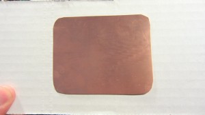 |
To begin, you need thin copper sheet. The thickness of the copper sheet should be around 3 to 4mil (0.003 to 0.004 inch). I got mine from Amazon: 12 inch by 12 inch for a reasonable price. Use scissors to cut a small piece from the sheet. The size should be twice as large as the actual PCB size, to avoid solder paste from running off the stencil. |
 |
Clean the copper surface using some Bar Keepers Friend. |
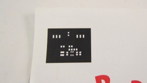 |
Now use a laser printer to print the color inverse of the top stencil mask onto a piece of magazine paper. Use the highest toner darkness. The color inverse means you want the stencil masks to be white, and the rest to be black. After etching, the solder masks will become holes in the sheet, thus creating a ‘stencil’. |
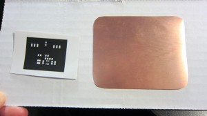 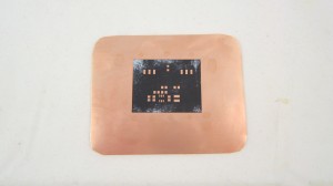 |
Now use the toner transfer method to transfer the print to the copper sheet. There are many online instructions for the toner transfer method, but according to my experience, the following two tips make it really a breeze. 1) Use magazine papers for the printout. Don’t use glossy photo papers — they are expensive and difficult to peel off. Magazine papers work like a charm. 2) Use a GBC laminator for transfer. It’s much, much easier (did I say much?) than a hot iron. Place the printout face down on the copper sheet, and run it through the laminator at least 10 times. Then throw the copper to hot water. After 5 minute you can peel off the magazine paper. Really easy. |
Etching
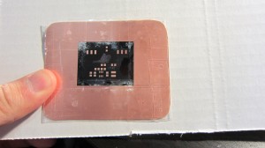 |
The next step is very important: you need to cover the bare copper surfaces with tape. This includes both the front and the back sides. You don’t want them to be etched out. Of course the tape should not run too much into the region of the printout — you don’t want to cover any solder mask holes that should be etched out. |
 |
Now it’s time to throw the thing into an etchant and let the exposed copper be etched out! Instead of Ferric Chloride, I like using the fast solution that consists of one part muriatic acid + two parts hydrogen peroxide. Very cheap in terms of material cost, and very effective. You can get muriatic acid from Lowes. Just be careful: do not let your skin touch it, and do not breath it directly. |
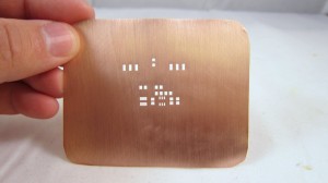 |
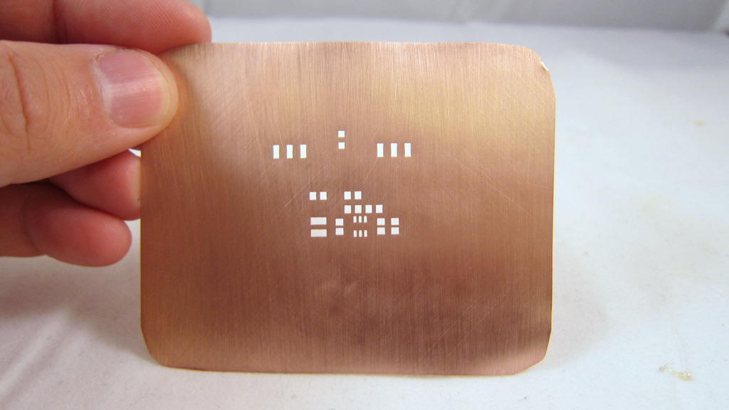
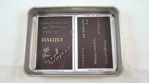
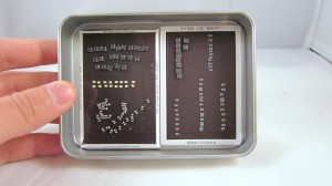
After etching is complete, carefully remove the tapes. Then use Acetone to remove the black toner. Finally, polish the copper surface with a Scotch-Brite scrub sponge. Voila, the solder paste stencil is done! Looks quite pretty. |
If you are experienced, the whole process should take no more than 40 minutes. You can make as many stencils as you want. I haven’t tried making a stencil with really small component footprints. I will try that at some point and see how accurate the stencil can be.
Apply Solder Paste
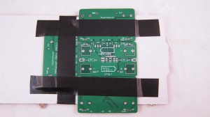 |
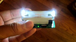
Now it’s time to see some stenciling in action! First, use three spare PCBs to make a tight frame, and insert the target PCB into the frame. My target PCB today is the AASaver / Breakboard Power Supply. This is a little boost converter that bumps a voltage as low as 0.8V to 5V or 3.3V, which can be used to power bright LEDs or serve as breakboard power supply. |
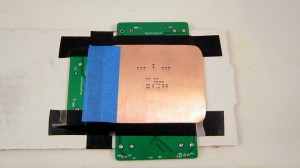 |
Carefully position the stencil on top of the target PCB, and align the holes with the solder pads. After you are satisfied with the alignment, use a tape to fix the left edge of the stencil. This way, you can easily life the stencil up when you are done, and you don’t have to re-align for the next PCB. |
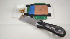 |
The next step is to apply the solder paste. This is a bit nasty. You need to prepare a putty knife (available in home improvement stores) and some solder paste. I got my solder paste from DealExtreme.com. Cheap and works really well (the only downside is the long shipping time). |
| I didn’t make a video to show how to apply the solder paste. Fortunately, Sparkfun electronics has a great video tutorial which I included on the left. Check it out! | |
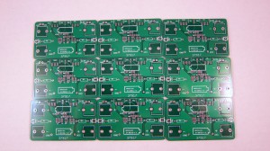 |
This is the outcome of applying solder paste to nine PCBs. Click on the image to see a zoom-in view. It’s really fast. |
Place SMT Components
Hot Skillet Reflow
|
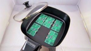
Now it’s time for some hot skillet action. Place several component populated PCBs into an electric skillet. Turn to the maximum power. In about 2-3 minutes the reflow will start to happen. As soon as it’s done, turn off the power and let the PCBs cool down. If you’ve never done the reflow before, check out Sparkfun’s awesome Reflow Skillet tutorial.
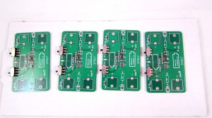
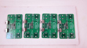
You should do this outdoors because the fumes produced during reflow are toxic, and you certainly don’t want to breathe them! The picture on the left shows the outcome of the reflow. |
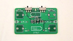 |
Lastly, perform careful visual checking to see if every component is soldered properly. Also do a basic electric test to see if the circuit functions correctly. |
The Final Result
Here you are, a fully functioning AA Saver / Breakboard Power Supply! I will write another blog article shortly to introduce this small yet very useful circuit. Stay tuned.
Vote on OpenSprinkler for the Best Internet of Things!
The OpenSprinkler project was nominated for the Best Internet of Things — Open Source Project category! If you like it, please consider giving it votes. Everyone has 3 votes, you can cast them on different projects, or all on the same project! Thanks!
http://postscapes.com/best-iot-open-source-project-2011
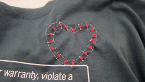
‘Sewing’ Wearable LEDs using Wire Wrap Wires
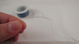
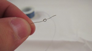
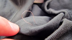
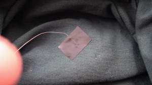
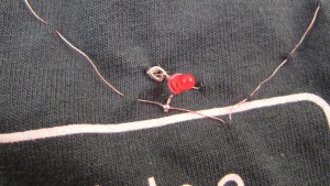
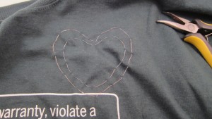
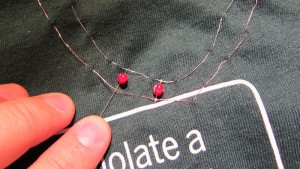
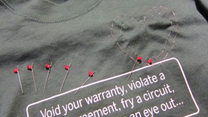
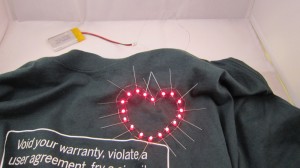
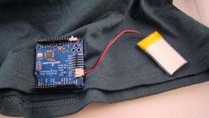
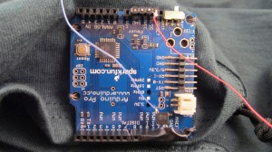
This week I am helping my school to organize a wearable electronics event for undergrads. Since none of us has done this before, the biggest question is to find out how to sew LEDs and other electronic components onto clothes. We ordered 2 spools of conductive threads, but shipping is a bit slow. While waiting for the order to arrive, I am thinking about alternative options to make wearable LEDs. Looking around my toolbox, I found some wire wrap wires. These are very thin, 30AWG wires typically used for wire wrapping. I was curious if it’s possible to use these thin wires for ‘sewing’ electronics onto fabric and clothes. After experimenting with it a bit, I found it is actually a feasible method. Check my end result first:
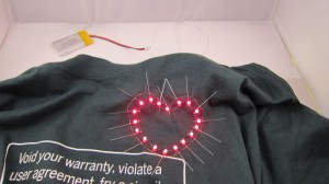
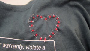
How does this compare to conductive thread?
- Pros
- No needle required, because the wire is stiff enough to go through fabric by itself.
- Solderable.
- Available in many stores and relatively cheap.
- Cons
- May break if stretched too much, again because the wire is stiff.
- Can form small curls during sewing if not careful.
Video demo:
So how does this method work? Just follow my illustrated examples below:
Learning Electronics — 1. Astable Multivibrator
This is the first article in a series that I call ‘Learning Electronics’. The goal is to learn and experiment with basic electronic circuits. The first circuit I will discuss here is the astable multivibrator. This is a very simple oscillator circuit that can be used to generate square waves. Here is the schematic of a standard astable multivibrator:
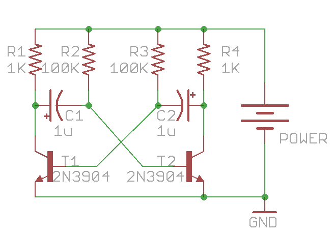
It consists of only two NPN transistors (T1 and T2), two capacitors (C1 and C2), and four resistors (R1-R4), organized in a symmetric fashion. The collectors of T1 and T2 are outputs, which provide complement square wave signals. The values of the capacitors and resistors can vary depend on the desired frequency, and their values do not have to be symmetric.
Update: as some readers pointed out, for square wave output, the resistor values should satisfy: R2 / R1 < h_fe, where h_fe is the transistor's current gain (same for R3 and R4). As h_fe is usually around 80 to 250 for 2N3904, the specific values above (R1=1K, R2=100K) are close to the margin. To improve this, consider increasing R1 or decreasing R2. Alternatively, you can replace 2N3904 with BC547, or even a Darlington transistor (e.g. MPSA14), which have higher h_fe values.
Principles
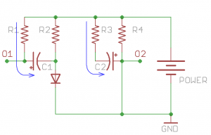
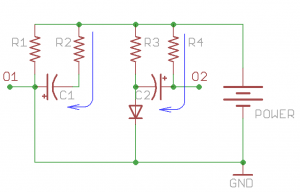
So how does the circuit work? To begin, when power is applied, theoretically both T1 and T2 should turn on, since their base pins are connected through resistors (R2 and R3) to Vcc. However, due to small differences in the electric properties, one of the them will turn on slightly earlier than the other. Without loss of generality, let’s assume T2 turns on first. Therefore, T2’s collector begins to conduct and can be thought of as ‘shorted’ to ground. Note that C2’s right lead is connected to T2’s collector, and since C2 is not charged yet, its left lead also has a voltage close to ground. This immediately shuts off T1, i.e. T1 becomes an open circuit. Therefore C1’s left lead is in floating status, and its right lead is connected to T2’s base, which is about 0.7V due to the forward voltage drop of transistors. This forward voltage drop is the same as a diode. So at this moment, the circuit is equivalent to the following:
During this period, T2’s collector (output O2) remains low, and C2 begins to charge through R3. Thus the voltage on C2’s left lead will rise, and the rising time depends on R3 x C2. At the same time, C1 also charges, through R1, which is typically a small resistor (e.g. 100-1000 ohm). So C1’s left lead (output O1) will quickly rise up to Vcc and remains high.
As C2 continues to charge, a critical moment will happen when its left lead rise up to 0.7V, at which moment transistor T1 will turn on, and its collector will conduct to ground. Note that since C1’s left lead is connected to T1’s collector, it will also drop to ground voltage. As C1 is fully charged, it’s right lead will suddenly drop to a negative voltage (-Vcc). This will shuts off T2 firmly. Therefore the circuit will suddenly transition to the following equivalent:
During this period, output O1 will remain low, and output O2 will quickly rise to Vcc (due to the charging of C2 through a small resistor R4). At the same time, C1 charges through R2 and the voltage on its right lead will rise over time determined by R2 x C1. Now you can predict what’s going to happen: as C1 continues to charge, the next critical moment happens when C1’s right lead rises above 0.7V. At that point, T2 will conduct again while T1 shuts off. The same cycle will repeat. There you go, oscillators!
Analysis
Now we have to do some calculus to find out the frequency of the oscillator. Let me focus on output O2. As it alternates between low and high, it approximates a square wave. How to find out the frequency? Note at the end of stage 1, C1 has a voltage of (Vcc – Vb) across it (where Vb = 0.7V). Again, the voltage establishes very quickly because R1 is small. The moment the circuit transitions from stage 1 to stage 2, C1’s right lead has an initial negative voltage: -(Vcc – Vb), and the circuit remains in this stage until that lead rises up to +Vb. So let’s calculate how long this will take. There are ready-made equations to compute this, but here let me derive it from basic differential equations.
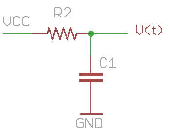 To start, the problem can be simply stated as follows: a resistor R2 and capacitor C1 are connected in series between Vcc and ground. C1 has an initial voltage of -(Vcc – Vb). How long does it take for C1’s voltage to rise up to +Vb? Let’s assume C1’s voltage is V(t): a function that changes over time. According to the law of capacitor, the change of V(t) is equal to the current flowing through it divided by the capacitance:
How much is the current i(t)? That’s equal to the current flowing through the resistor R2, thus
putting them together:
This is a simple differential equation. We can rearrange it to the following form:
By using the fact that
and integrate both sides, we get:
where K is a constant. Using the knowledge that when t=0, V(t)= -(Vcc – Vb), we find out
so:
Recall that our goal is to find hen V(t) is equal to Vb, so substitute Vb to V(t), and solve for t:
Under the assumption that Vcc is much larger than Vb, this is approximately equal to:
This is how long stage 2 will last. Similarly, stage 1 will last for approximately
Therefore, a full cycle will take
before the next cycle begins. The frequency of the wave is thus:
Viola! We are done!
With the given values in the first schematic (C1=C2=1uF, R2=R3=100K), the frequency is roughly 6.5Hz. These symmetric values can produce a square wave of 50% duty cycle. But they do not have to be symmetric. By using different R2 and R3 (or different C1 and C2), you can easily create waves with any desired duty cycle.
Practice
It’s very easy to prototype the circuit on a breadboard. Here is an example:
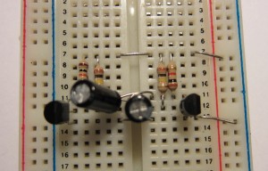
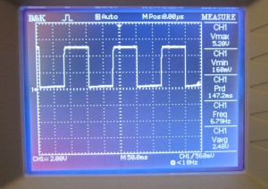
Connecting an oscilloscope to output O2, the result shows a decent square wave with 50% duty cycle at about 6.7Hz. Looks quite nice.
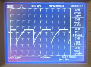 I also checked the signal on T2’s base pin. The result is on the left. As you can see, the beginning of stage 2 is signaled by the jump to a large negative value. During this stage, C1 charges through R2, so T2’s base voltage rises continuously. As soon as it crosses Vb, T2 conducts, and its base remains at Vb until the start of the next cycle.
Next, let’s blink some LEDs with the oscillator. You can either connect LEDs in series with R1 and R4, or directly to output O1 and O2. Check the video below (the circuit below uses C1=C2=10uF):
Finally, if you want, you can make a printed circuit board, so you can carry it around, or use it to decorate a toy with flashing LEDs. Enjoy!
Appendix
Frequency change when connecting LEDs with R1 and R4 in series
As mentioned above, one way to connect LEDs into the multivibrator is by putting them in series with R1 and R4. One interesting thing I noticed is that when doing so the frequency of the LED blinking is much faster than the calculated frequency. So what’s happening? A careful analysis reveals that this is not surprising. The main reason is that because the LED will drop about Vled=2V, C1 and C2 will not be charged all the way to Vcc-Vb anymore. Instead, they are charged to about Vcc-Vb-Vled. Consequently, it takes less time for C1 or C2 to charge from a negative voltage to +Vb, hence the oscillation frequency is faster. The precise formula is actually:
Since Vb+Vled is quite significant compared to Vcc, we cannot make the same approximation as above anymore. For example, with the given values in the first schematic (C1=C2=1uF, R2=R3=100K), and assume Vcc=+5V, the frequency is now roughly 10Hz (compared to 6.5Hz when LEDs are not connected). So this explained why the LED blinking speed seems faster than calculated.





 Stage 1
 Stage 2