WiFi-enabled Color LED Matrix using ESP8266 and WS2812 LEDs

Last Thursday I had a lot of fun doing a workshop at my college (UMass Amherst) where I taught students to use a WiFi-enabled Color LED matrix combined with Javascript programs to create animations displayed onto the LED matrix. The matrix is made of 5×7 WS2812 (NeoPixel) LEDs. I’ve actually designed it two years ago and wrote a blog post about it. Back then I was using an Arduino-compatible SquareWear Mini to control the display patterns. It was fun to play with, but changing the display patterns require modifying the Arduino sketch and upload it over and over again, which took a lot of time.

This time, I improved the design by simply using a ESP8266 WiFi chip mounted at the back of the LED matrix. I wrote a firmware with a minimal set of HTTP GET API, with which you can set all pixels colors, set the brightness, or tell it to scroll a line of text. What’s cool about it is that you can now use Javascripts to send animation frames to it on the fly, which is a lot easier compared to re-writing and uploading an Arduino sketch. In addition, you can take the LED matrix on the go and use your mobile phone to control it, which is nice for wearable electronics.

img_20161029_234314

The video below goes through the details. Take a look at it first. Essentially, combining ESP8266 with the LED matrix makes a little wireless display. The next thing I should work on is to figure out how to stream video to it. It’s going to be very very low resolution for sure, but it’s gonna be fun, and I can always daisy chain multiple matrices to make a larger display.


Workshop Materials

Below you can download the materials I prepared for the workshop, including the Arduino firmware code (compilable in Arduino using ESP8266 core with NeoPixel library), the Javascript programs I wrote, and the powerpoint slides with lots of details and can be used as a 1-2 hour tutorial.

Also, the LED matrix and ESP8266 development board that I used in the demo are both designed by myself. They are attached together by double-sided tape and three soldered wires. The hardware design files are available in my Github repository below:


Introducing SquareWear Mini, with All-New Chainable Color LED Matrix, and an Interactive Animation Design Tool

Liked how SquareWear 2.0 has so many built-in components and yet so compact in size? Introducing SquareWear Mini — the little sister of SquareWear that has the same capabilities (and more!) but is 25% smaler in size!

sqrwear_mini_header

SquareWear Mini

Available for purchase at Rayshobby Shop.

So what is SquareWear Mini? Similar to SquareWear 2.0, the SquareWear Mini is essentially an Arduino running at 3.3V and 12MHz. It is based on the ATmega328 microcontroller, and it has a load of build-in components, including USB port, power switch, pushbutton, buzzer, temperature sensor, light sensor, MOSFETs, lithium battery jack, and lithium battery charger. The pins have enlarged sizes for sewing with conductive threads, for soldering sew-on snaps, and they are great for touch sensing too.

How did I shrink it to be smaller than the original SquareWear? Well, by removing the on-board rechargable coin battery and color LED, and routing some pins to the side. With the space saved, I was even able to add a 16KB I2C EEPROM for storing extra data. Shortly you will see how this is useful. These changes were made because SquareWear designed specially to be attached to a chainable color LED matrix. This will enable a whole new set of exciting projects, as you can see from the video above.

IMG_3015squarewear_mini_annotation

Color LED Matrix

So let me briefly explain the LED matrix. Each matrix contains 35 LEDs arranged on a 5×7 grid with 8mm spacing. It uses the WS2812B color LEDs. These are great because the LED has a built-in chip that allows you to daisey chain them in bulk and still be able to individually set the color of any LED with only one microcontorller pin. Adafruit gave them a name calle the Neopixels. No matter how many LEDs you have, you only need 3 pins to get them to work, namely the VCC, GND, and DATA_IN pins.

These pins are mapped out at the back of the LED matrix. The locations of these pins exactly match the VCC, GND, and digital D10 pins on SquareWear Mini, so you can easily attach SquareWear Mini with the LED matrix by either soldering some sew-on snaps, or directly soldering the two boards together.

IMG_3048IMG_3049IMG_3033IMG_3037

The resolution 5×7 is not a whole lot, but it is sufficient to display ASCII characters and a lot of cute icons:

IMG_3044IMG_3057IMG_3058IMG_3059

The LED matrix is designed to be chainable too. Each board has DATAIND pins on one side, and DATAOUT on the other side. To extend the number of boards in the X direction, just place two matrices side by side and solder across the 6 pins on the boundary. The solder will get the two boards firmly attached to each other. Chain several boards together to make a large display panel, and it’s great for showing text and messages in any color you want. For example, you can use it as a name tag, or a thermometer (remember, SquareWear Mini has a built-in temperature sensor!)

IMG_3050IMG_3107_comb

You can also extend the panel in the Y direction. To do so, use three wires to connect the VCC, GND, and DATA_OUT pins of the previous row to the VCC, GND, DATA_IN pins of the next row. Also solder across the pins on the vertical direction to firmly attach the two rows of boards together. There you go, a bigger panel to display more detailed graphics!

IMG_3051IMG_3110

Software Demos

We’ve re-worked the SquareWear software library to include LED matrix demos. These demos work on both the original SquareWear 2.0 and SquareWear Mini. Check the video above for selected examples. The demos are included in the pre-configured software package, and are also available for downloaded individually at the SquareWear Github repository.

What I want to highlight here is the Flipbook Animation demo. It’s a great demo that allows you to interactively design pixel patterns and even an animation. SquareWear Mini can store the frame data into the I2C EEPROM and play it back later. Even better, it comes with sounds too! So how does this work? First, you upload the Flipbook Arduino code to SquareWear. Then, run the Flipbook host software. The host software is written in Processing and is cross-platform. It uses the HID Serial interface to communicate with SquareWear. In the host software you can click on pixels and assign them color values. These values are immediately transferred to SquareWear so you can preview the frame in real-time. For each frame you can specify the frame time and optionally a music note to play. You can create multiple frames, navigate through each frame, make modifications, save the animation to a disk file etc. At last, when you are satisfied with it, click on ‘Transfer to Device’ and the data will be stored into EEPROM. Next time you turn on SquareWear, just click the pushbutton and it will play back the stored animation. Isn’t that cool? With this tool, you never have to think about converting pixel patterns to programming code any more. Let your creativity and imagination take over!

viscap2viscap11

Hope you like SquareWear Mini, and let us know your cool project ideas!


SquareWear 2.0 used at Mount Holyoke College’s iDesign Studio Class

This past week has been a hectic week. Since SquareWear 2.0 got posted on Hack A Day, things have gone quite wild: we’ve got hundreds of orders, and the SquareWear YouTube video accumulated 80,000 views in just two days. By the end of last week, it has exceeded 100,000 views and has officially become the most popular video at the my YouTube channel.

Among the many emails I received, one common question is what can one use SquareWear for other than the examples demonstrated in the video. Well, at heart SquareWear 2.0 is really just a small Arduino with lots of built-in components (notably built-in rechargeable battery and USB port). The large pin pads make it suitable for wearable electronics projects, and the small size makes it suitable for general-purpose microcontroller projects. For example, I’ve used SquareWear to build a reflow oven controller, a OpenSprinkler Pi tester, a USB-based remote for RF power sockets. It’s really versatile.

If you are looking to make some artistic projects, you will be glad to hear this: SquareWear 2.0 was used at the Mount Holyoke College for their iDesign Studio Class. This class was offered by my friend Audrey Lee last semester, and they’ve just concluded the class last month with a fantastic final presentation. I am going to highlight some of the best projects below. For additional information, check the link above — each project has a website with detailed write-up. I am sure they will inspire you to come up with your own fantastic project idea.

One of my favorite is the Accelexpression project by Madeline Ketley. She combined a SquareWear with a gyro sensor and NeoPixel LED strip to make a smart skirt for dancers. The LED strip displays different colors depending on the standing position of the dancer. It is not only artistic and visually beautiful, but it’s a very useful tool for training dancers: from the color of the LEDs you can easily tell if the dancer is standing straight, or if two dancers are synchronized in their moves. It’s a brilliant idea and I was completely impressed. Here are some rather blurry pictures. I wish I had taken high-quality pictures or even better a video!

IMG_3796IMG_3797IMG_3823

Another favorite of mine is Meaghan Sullivan’s Reading Hardwired. Meaghan made a hand-drawn picture book featuring a timid and cute cameleon. She then combined a SquareWear, copper sheets, some neopixels, and photo-resistors to make the picture book change colors as you turn the pages. It’s so artistic, vivid, and truly brilliant!
IMG_3812IMG_3813

Neopixels seems to be a big hit among students. Alexis Andrus used strips of Neopixels to make a beatuful iDesign Jacket; Ione Brogna also used Neopixel strips to make iTech Accessories, such as these stylish shoulder straps belts. Ione also added a sound sensor to SquareWear and made her iTech accessories respond to music and beats.

IMG_3780IMG_3783IMG_3786IMG_3822

Next up, with Julia Rycyna’s La Coeur du Dragon project, we enter the fantasy land of dragons. She first made a plush dragon with flapping wings using a SquareWear and some muscle wires. Thanks to the build-in MOSFETs on SquareWear, no external muscle wire drivers were needed. Then she added a ultrasonic distance sensor and a LED heart to the dragon, so that the heart blinks faster as you approach the dragon. Quick, hold it tight, how can you bear with putting such a lovely dragon down!

IMG_3807IMG_38202534840_orig

Safae Lahgazi Alaoui presented an amazingly artistic project called the Interactive Mirror. The mirror is decorated with LEDs and responds to sound, touch, and motion. Check the images below and appreciate the complexity of the mirror.

IMG_3802

Eva Snyder’s musicTouch project is a great educational tool to teach kids about music and tones. It uses conductive ink and touch sensing to let you play music interactively. If you are interested, be sure to check out my previous blog post about how to use SquareWear to create a touch-based digital piano without any additional hardware.

IMG_3808

Thinking of some other creative uses of SquareWear? Saadia Gabriel made a solar charging jacket called The Turtle? It makes use of SquareWear to charge a lithium battery, which is then bumped to 5V using a boost converter for charging cell phones. Athena Donta and MJ Lee created the Bad Weather Wear project, which combines a SquareWear, LED matrix, and conductivity sensor onto a pair of mittens. When it rains or snows, the LED matrix displays smileys and different patterns to keep you happy in bad weather. Isn’t that sweet?

IMG_3793IMG_3789IMG_3790

If you are inspired by these projects, consider getting a SquareWear 2.0 from our shop. It’s a great little gadget to help explore the creative and artistic side of you!

Announcing AASaver 2.0 (with USB and LiPo charging)

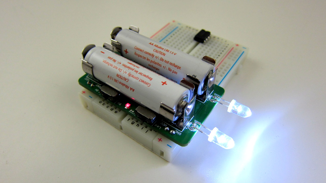
Three months after its first prototype version, I am glad to announce that the long-awaited AASaver 2.0 has finally become available! In case you haven’t seen the first version of AASaver: it is basically a versatile boost converter that takes two AA (or AAA) batteries and bumps them to 5V so you can use it to power flashlight LEDs, or use it for breadboard experiments. The nice thing is that since it’s based on an efficient boost converter chip that has low start-up voltage, it can work with both new and used batteries. Even if the batteries can no longer work in other devices, like remote control, electronic toys, you can still use the AASaver to light up LEDs and run circuit board experiments for a long time. It’s a great way to harvest the remaining energy (or in layman’s term, suck the remaining juice) in your ‘dead’ AA batteries 🙂


The New Design

IMG_3016IMG_3011
IMG_3009IMG_3017
AASaver 2.0 is a completely redesigned circuit from its 1.x version. Here is a list of new changes:

  • Added USB port, which allows charging of USB devices such as mobile phones, MP3 players etc. To support up to 500mA charging current, the booster converter is changed to use NCP1450A, an upgrade from the previous MCP1640.
  • Added lithium battery charger (based on MCP73831), which allows charging of lithium polymer (LiPo) batteries from AA batteries. There is an on-board LiPo battery jack, and an SMT pot (trimmer) to provide adjustable charging current.
  • There is also an input LiPo jack, so the circuit can take source either from AA batteries or external LiPo battery. There is a good reason to provide this functionality, as explained below.
  • The original battery clips are changed to a plastic battery holder, which is mounted with screws on the back of the component side. This frees a lot of room on the component side, which in turn reduces the PCB size.
  • The breadboard pin headers are now changed to the battery holder side. The AASaver now takes much less space when plugged into breadboard. An additional pair of pinouts are also added to fit breadboards with extended width.
  • It’s also possible to use the circuit for solar charging, and charging LiPo battery from external USB port.

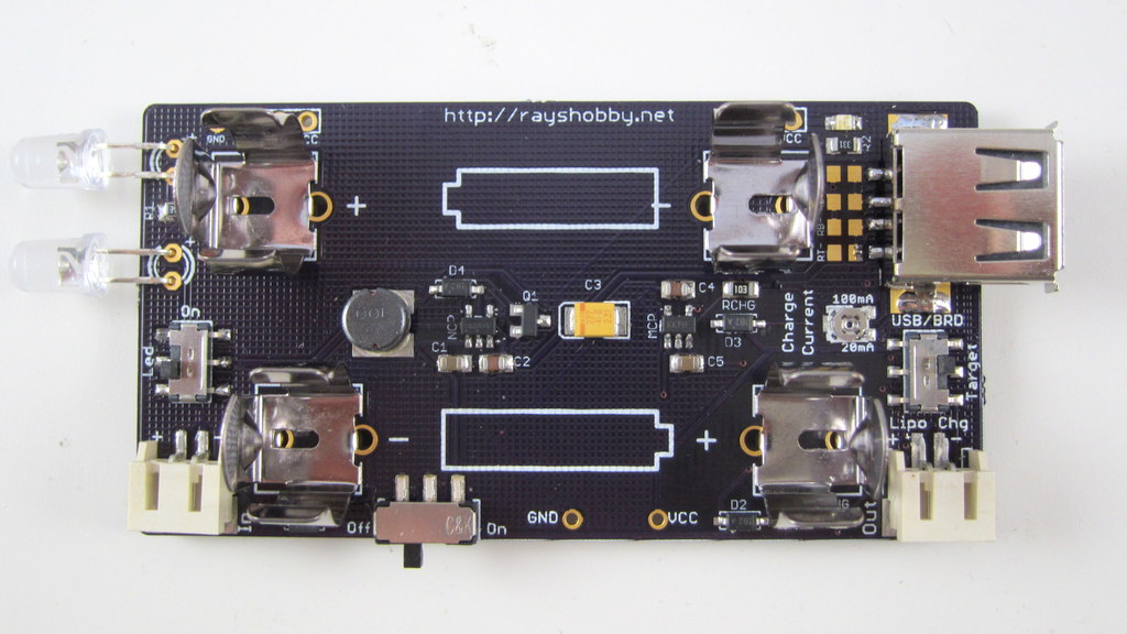
In sum, this version preserves the same basic functionality as before, which is to take two AA (or AAA) batteries and serve dual functions as an LED flashlight and breadboard power supply. But it also has a lot of new features and improved usability, most of which were adopted from user suggestions on the original version. Here is a quick summary of the spec:

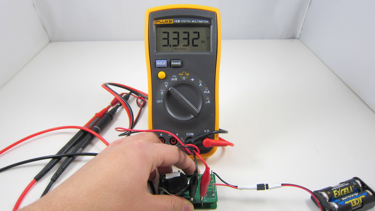
  • Power Source: two AA/AAA batteries, or external 3.7V LiPo battery (selecctable by an on-board switch). Can also be modified to work with a single battery, or with a solar cell.
  • Power Output: any of the following: flashlight LEDs (seletable by a switch), breadboard pin headers, USB, or LiPo charger. The LiPo charging current is adjustable from 10mA to 200mA through an on-board trimmer.
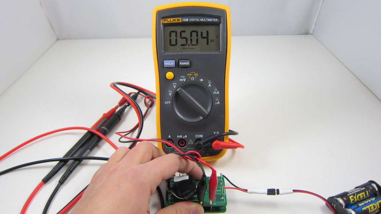
  • Output Voltage: 5V up to 500mA.

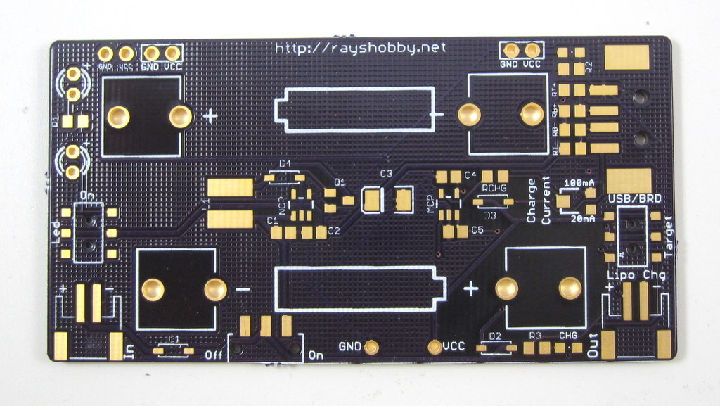
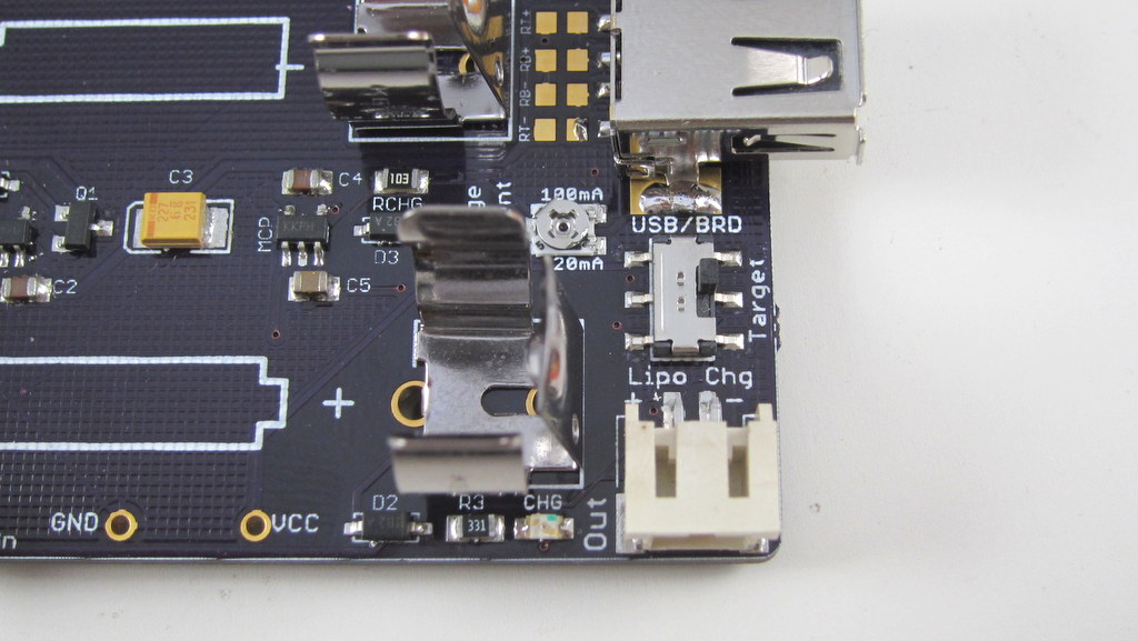
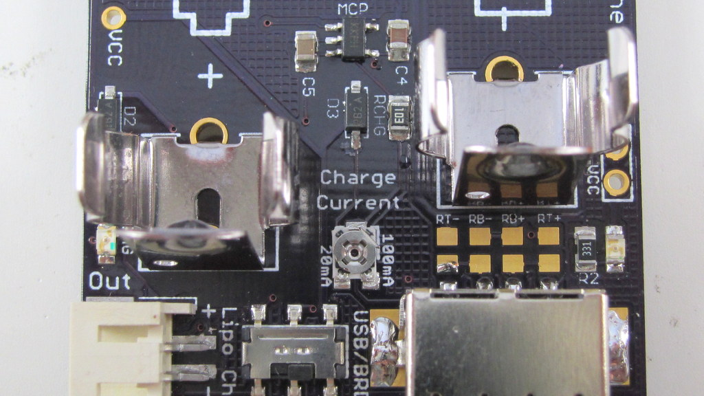
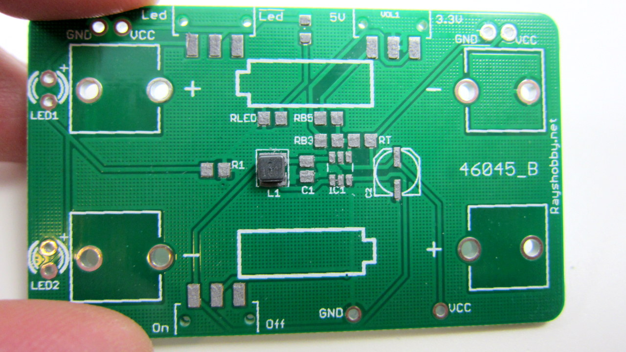
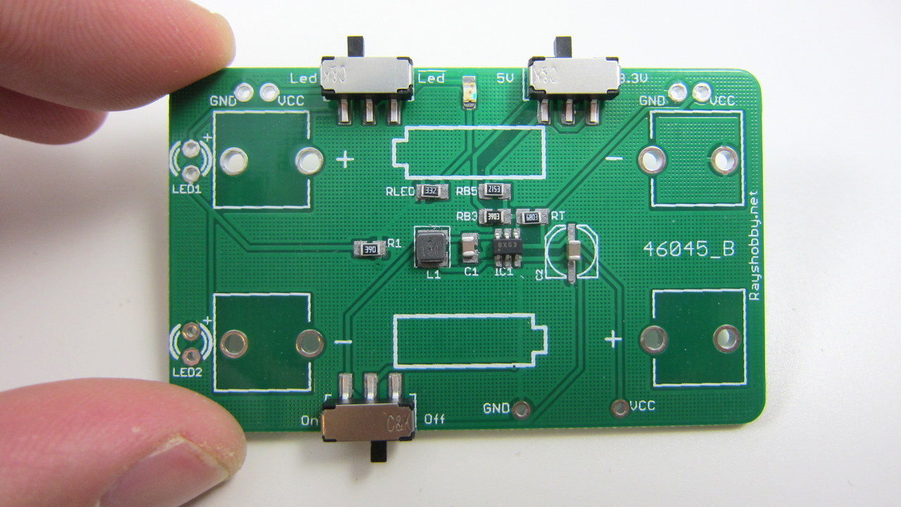
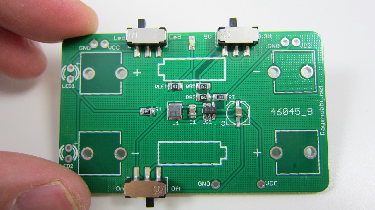
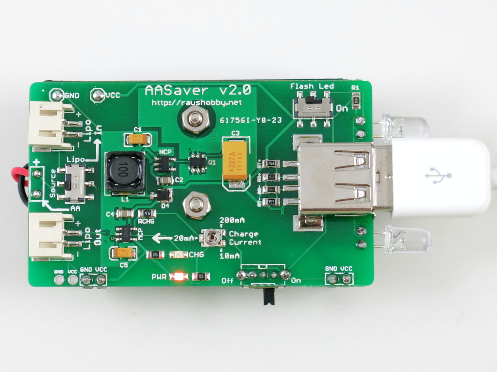
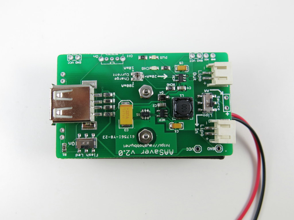
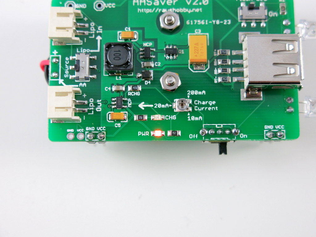
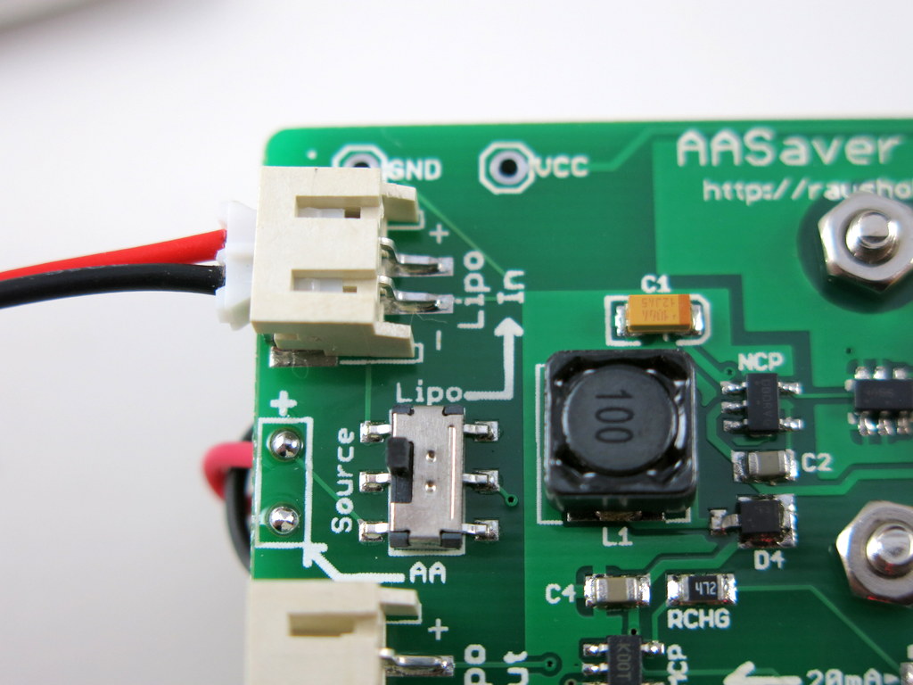
Here is an annotated diagram for the various on-board components:aasaver2_diagram

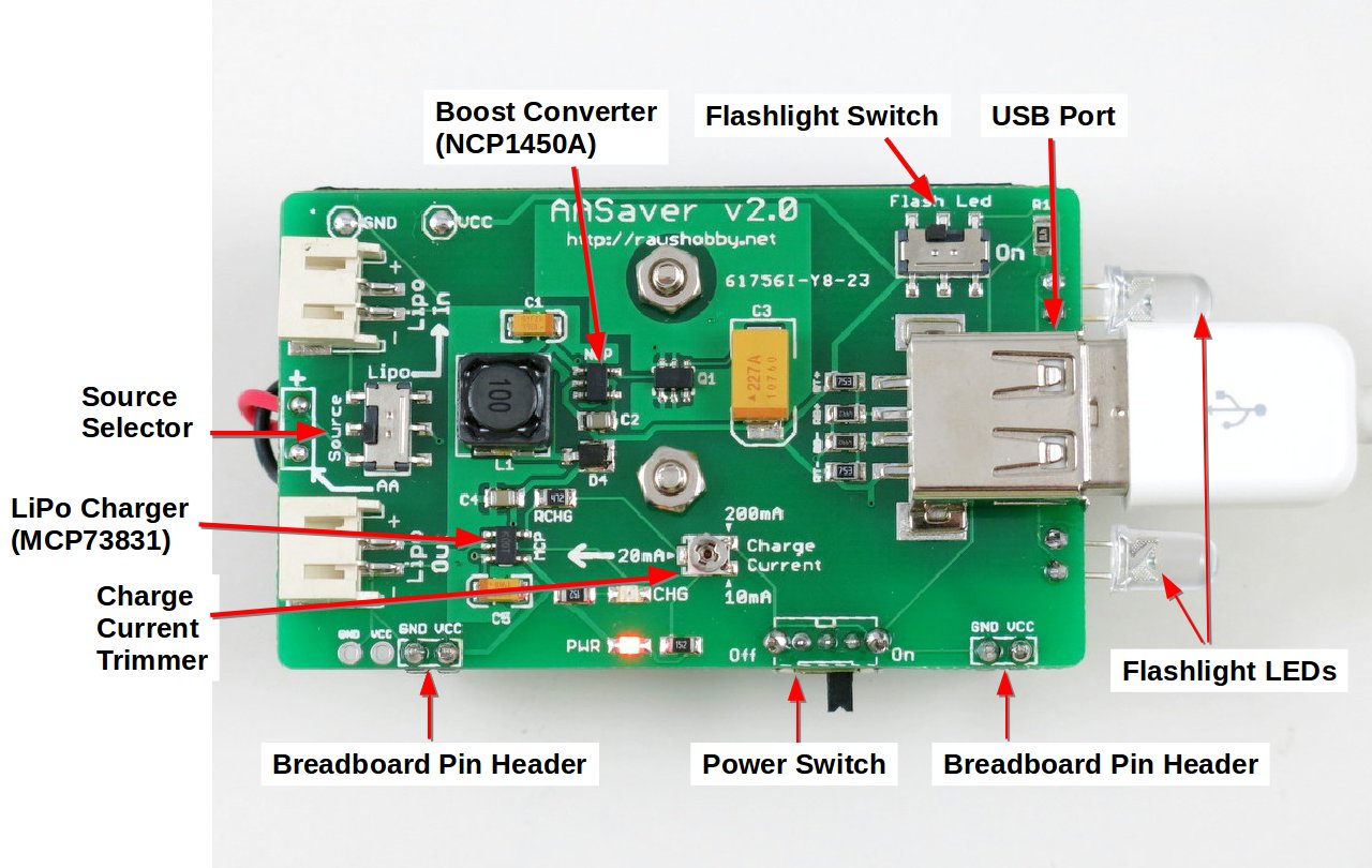
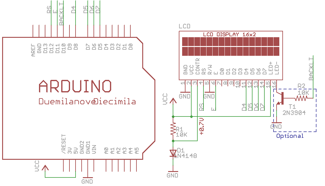
Schematic and Board Design

Acknowledgement: the USB charging circuit, particularly the D+/D- line voltages, references the design of the MintyBoost by Lady Ada. Check the details about USB charging therein.

Technically AASaver 2.0 is different from the MintyBoost in that 1) it uses a different boost converter chip (NCP1450A vs. LT1302); 2) it has a built-in LiPo charger; 3) it uses SMT components and is mostly assembled. Also, AASaver is designed to be versatile and serve multiple functions, including LED flashlights, breadboard power supply, USB charging, and LiPo charging. Its primary goal is to make use of old batteries (hence the name AASaver 🙂 ).


The Kit

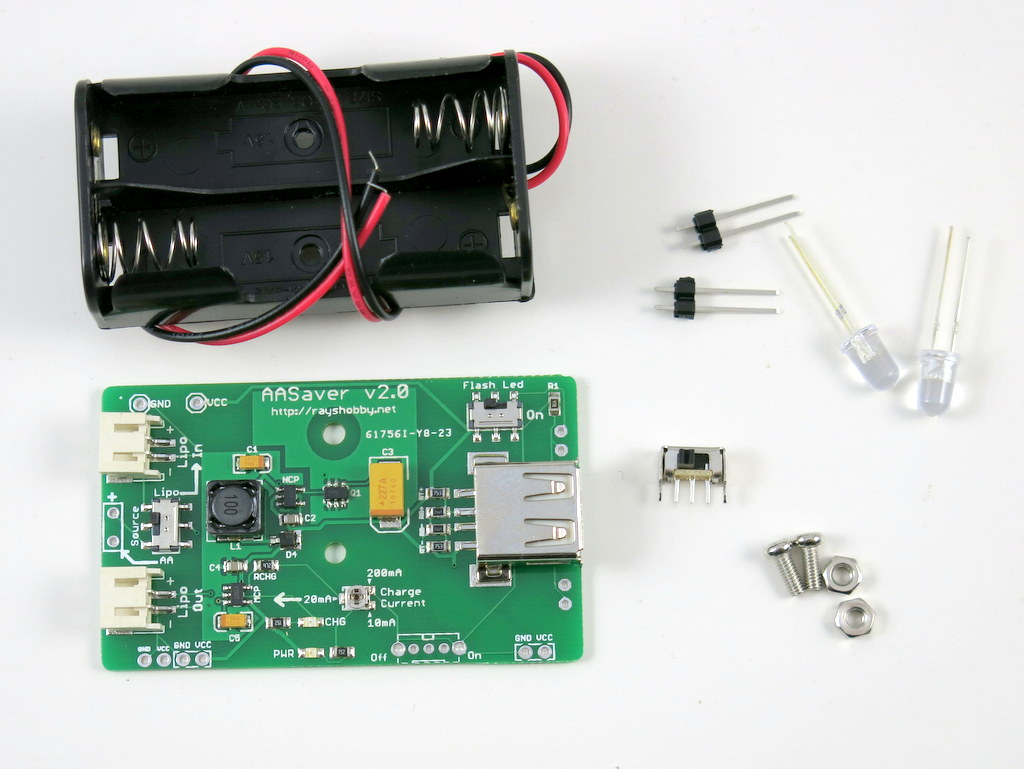
A limited number of the AASaver 2.0 kits are now available on Rayshobby Shop. More will become available in the upcoming weeks. Included in the kit are one assembled and tested AASaver 2.0 circuit board, battery holder, two pin headers, two bright flashlight LEDs, a power switch, two screws and nuts.

IMG_2982IMG_2981


Assembly and Usage Instructions

Although the circuit board is mostly assembled, it does require a few simply assembly and soldering steps to get it fully functional. If you’d rather not assemble and solder anything, you can order a completely assembled AASaver at additional cost. The instructions are posted below with high resolution images. These instructions will soon be posted on the AASaver homepage.

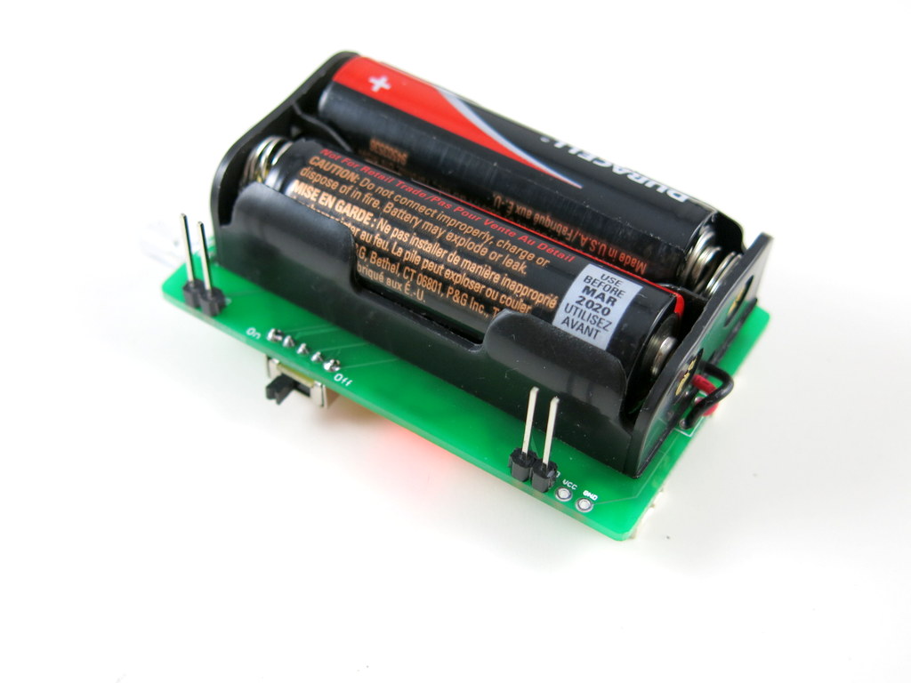
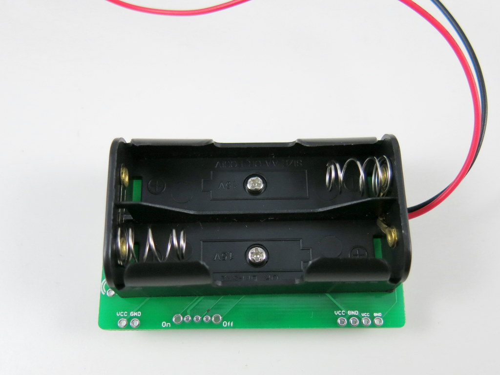
Step 1. Attach the Battery Holder

Use the two screws and nuts to fix the battery holder at the back of the PCB. Make sure that the battery holder wires are close to the side with the AA/LiPo Source Selector (i.e. the opposite side of the USB port).
IMG_2983IMG_2984

Next, cut the battery holder wires to about 1 to 2 inches long (don’t cut it too short, or otherwise you will have difficulty soldering it later). Then use a wire stripper to strip the lead, and then insert the wires to the PCB holes and solder them. Make sure that the red wire goes into the hole marked ‘+’, because this is the positive wire. Double check yours with the image on the right below.
IMG_2985IMG_2986

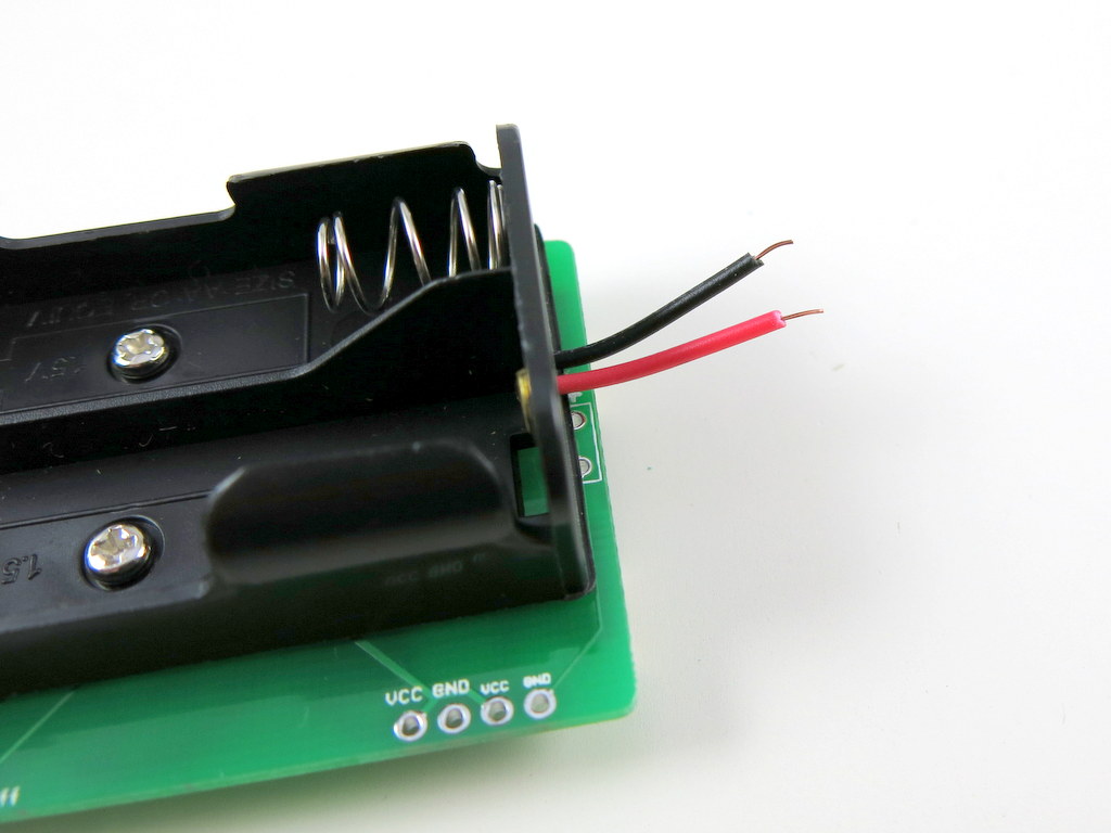
If you want, you can use a little bit of hot glue to fix the wires in place. This is not required, but is helpful as the wires are very thin and are prone to breaking if you wiggle them too much.

Step 2. (Optional) Solder the Breadboard Pin Headers and LEDs

Now you need to solder the breadboard pin headers and flashlight LEDs. NOTE: these steps are optional, and depends on what you want the AASaver for. If you don’t need it to run breadboard experiments, you don’t need to solder the pin headers (or you can always solder them later).

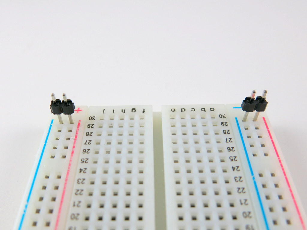
To solder the pin headers, first insert the two pin headers towards the end of a breadboard. This will help fixing them in place during soldering. Next, align the PCB holes on the AASaver with the pin headers. The height of the pin headers are designed to match the height of the battery holder, so if everything is correct, the battery holder should sit flat on the same surface with the breadboard. Note that this only works if the pin headers are inserted towards the end of a breadboard — if they are inserted in the middle of a breadboard, the battery holders will sit on top of the breadboard and this won’t work.

Also note that on the left side there is an additional pair of VCC-GND pin holes. These are designed for breadboards with extended width. So if your breadboard is wider than the one shown in the picture below, use the extended pair of pin holes.
IMG_2990IMG_2991

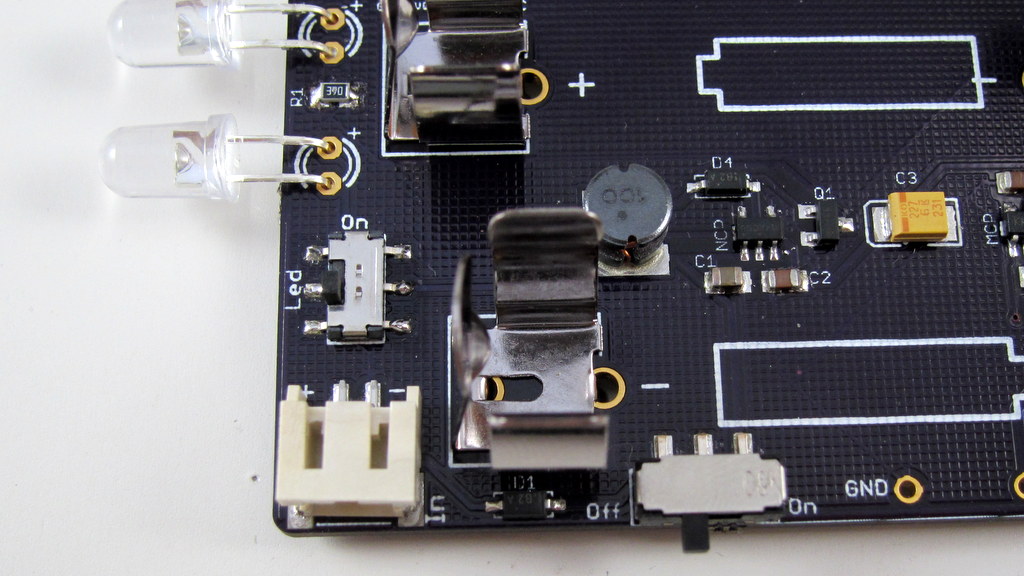
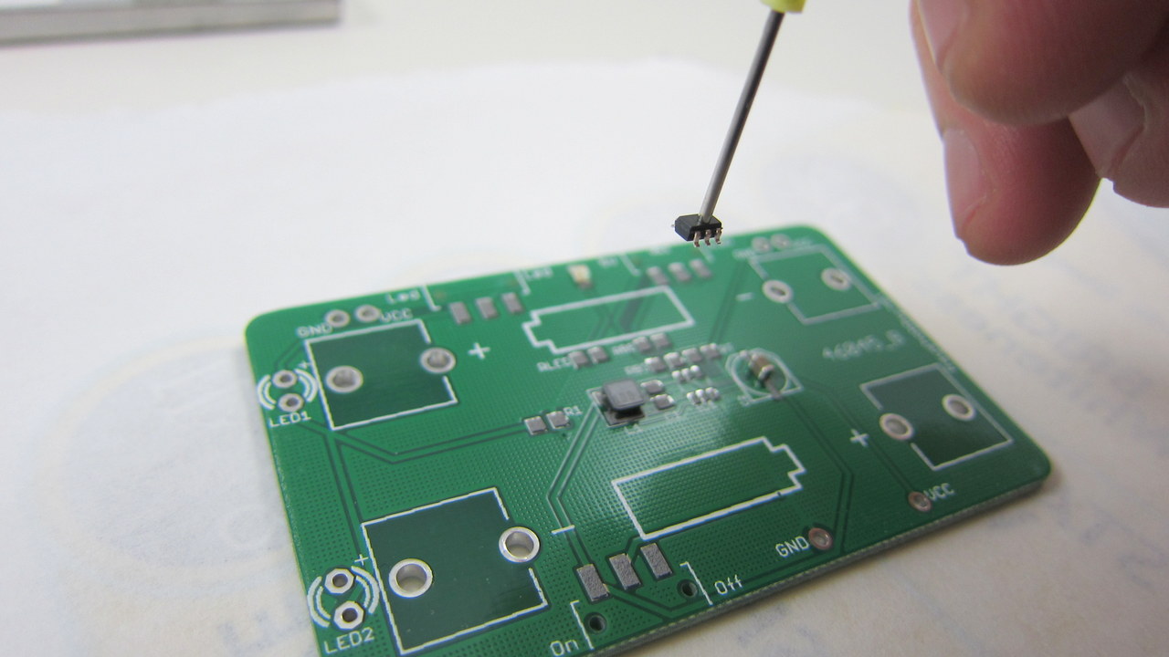
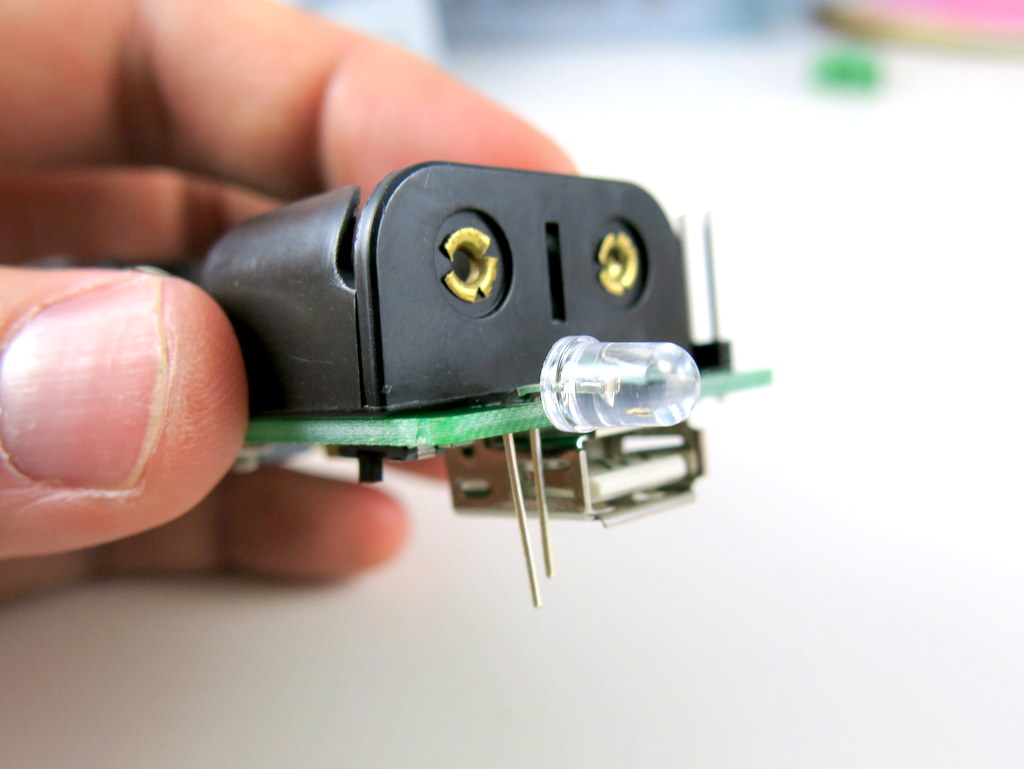
Next, to solder the flashlight LEDs, first insert the LEDs to the LED pin holes. These pin holes are located on the same side as the USB port. Make sure the longer lead of the LED goes into the hole marked ‘+’, as the picture below shows. Then gently bend the LED to 90 degrees, and solder the two leads. You can decide how long the LED should stick out of the circuit board, but in general, keep the LED close to the circuit board so that it doesn’t get accidentally bent. Once the LED is soldered in place, remember to cut the excessive leads. Follow the same process to solder the other LED.

IMG_2992IMG_2993

Now the AASaver is completely assembled! Below are the usage instructions.

Step 3. Power it On and Flashlight LEDs

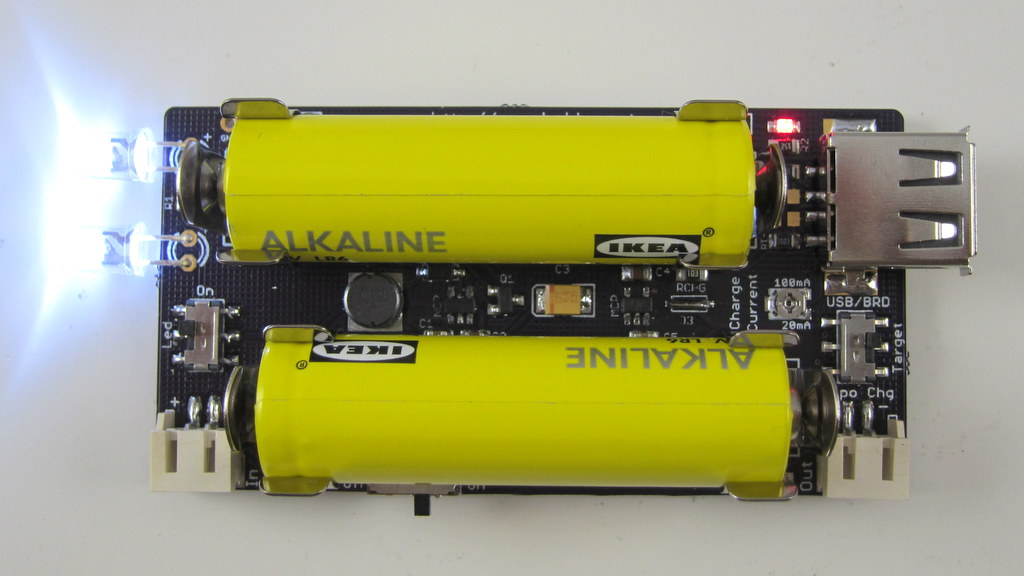
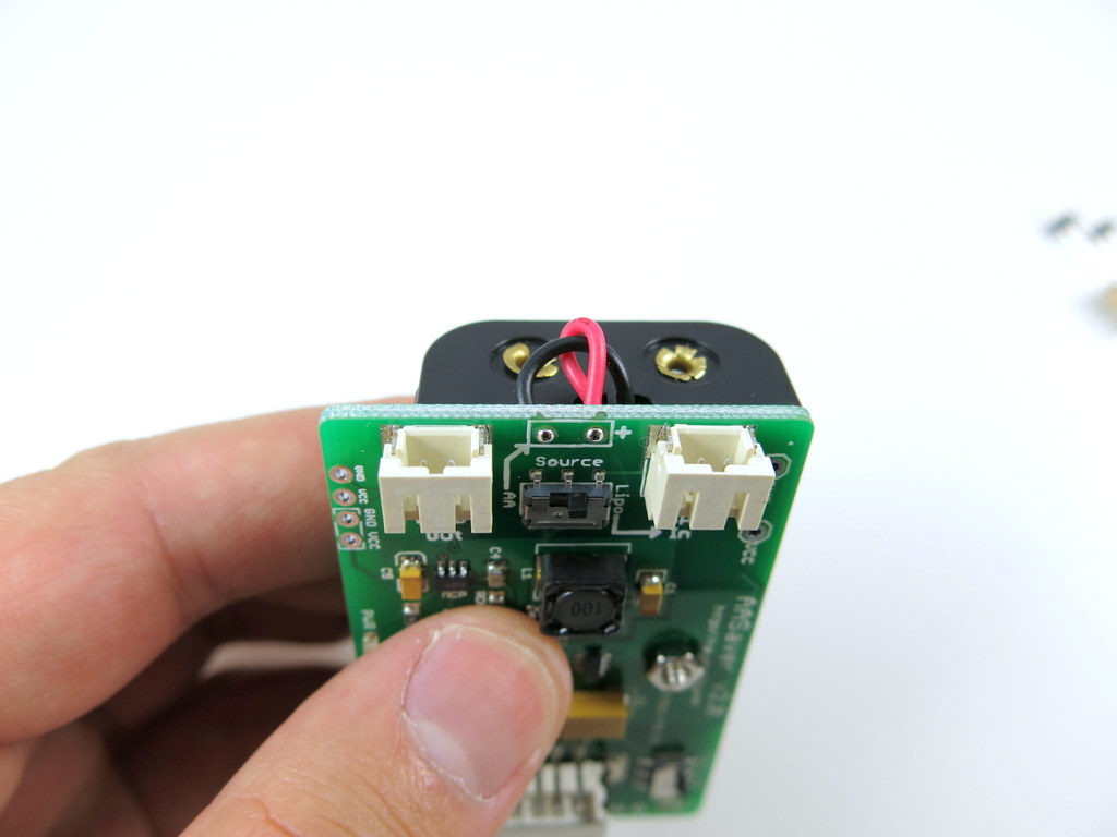
Pop in two AA batteries. Make sure you insert them in the correct orientation. Then turn on the power switch. The red Power Indicator LED should light up. If not, check the Source Selector Switch, and make sure it’s turned to ‘AA’ (instead of LiPo In). The Source Selector allows you to select either AA or LiPo as the power source.

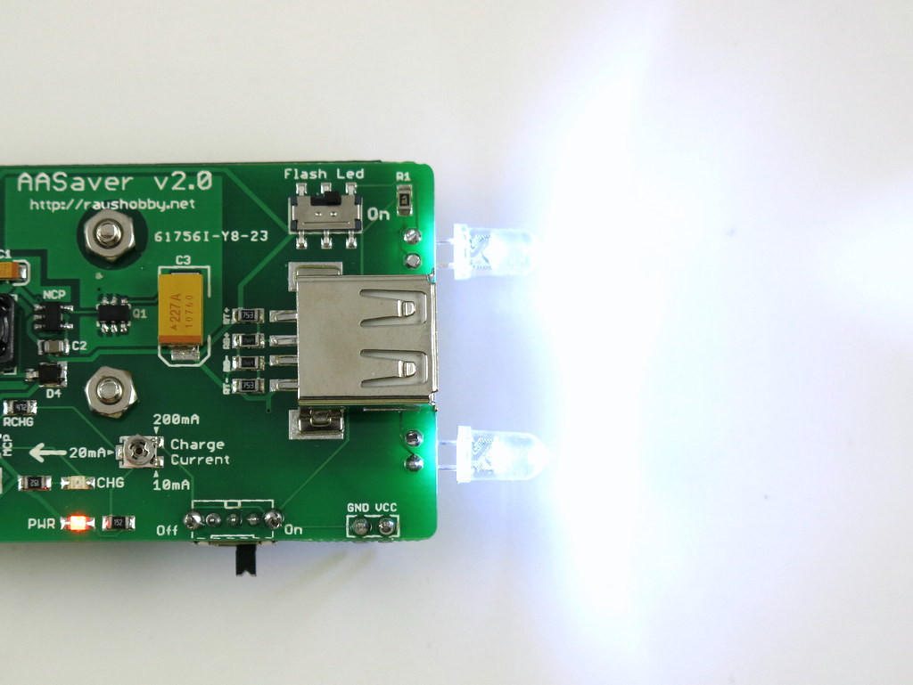
Next, turn Flash LED switch to ‘On’, and the two flashlight LEDs should light up. These are two bright flashlight LEDs, which work really well in the dark.

Note that the battery holder also sort of works for AAA batteries, although the contact is not very reliable. So if you want to pop in AAA batteries, try to use a small piece of aluminum foil to fill the gap between the AAA battery with the battery clips inside the holder. This should make it work perfectly.
IMG_2996IMG_3017

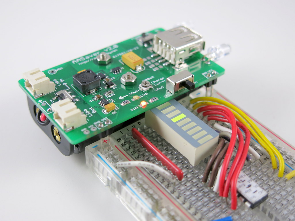
Step 4. Use it as BreadBoard Power Supply

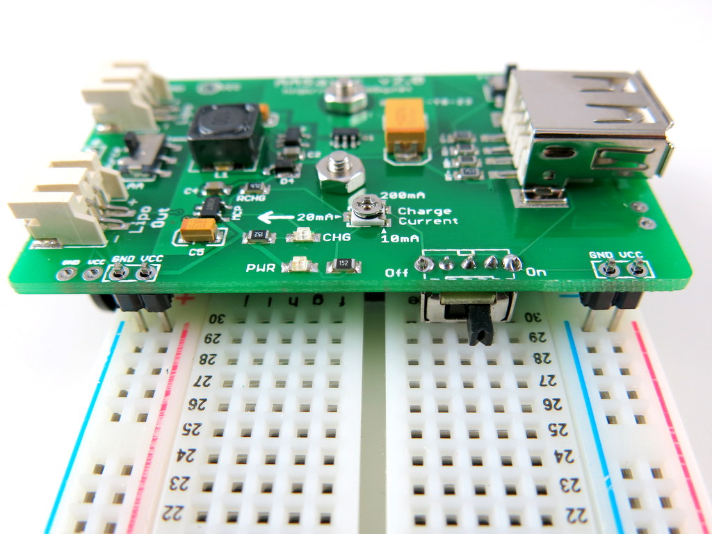
AASaver is also designed to function as a breadboard power supply. It provides regulated 5V, which is great for many circuit board experiments. To use this function, simply plug the AASaver (with pin headers down) into a breadboard. Note that unlike the AASaver 1.x, the body of the AASaver 2.0 will stay out of the breadboard, so this gives you more room on the breadboard.
IMG_3009IMG_3011

Step 5. USB Charging

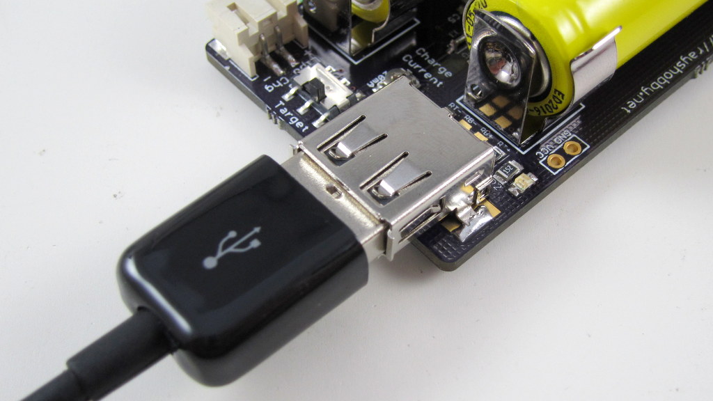
This is probably the most exciting new feature of the AASaver 2.0: you can now use it to charge USB devices. There is a built-in USB port that fits most standard USB cables. use it to charge your mobile phones, MP3 players, or anything that can charge through the USB port.

IMG_3001IMG_3016

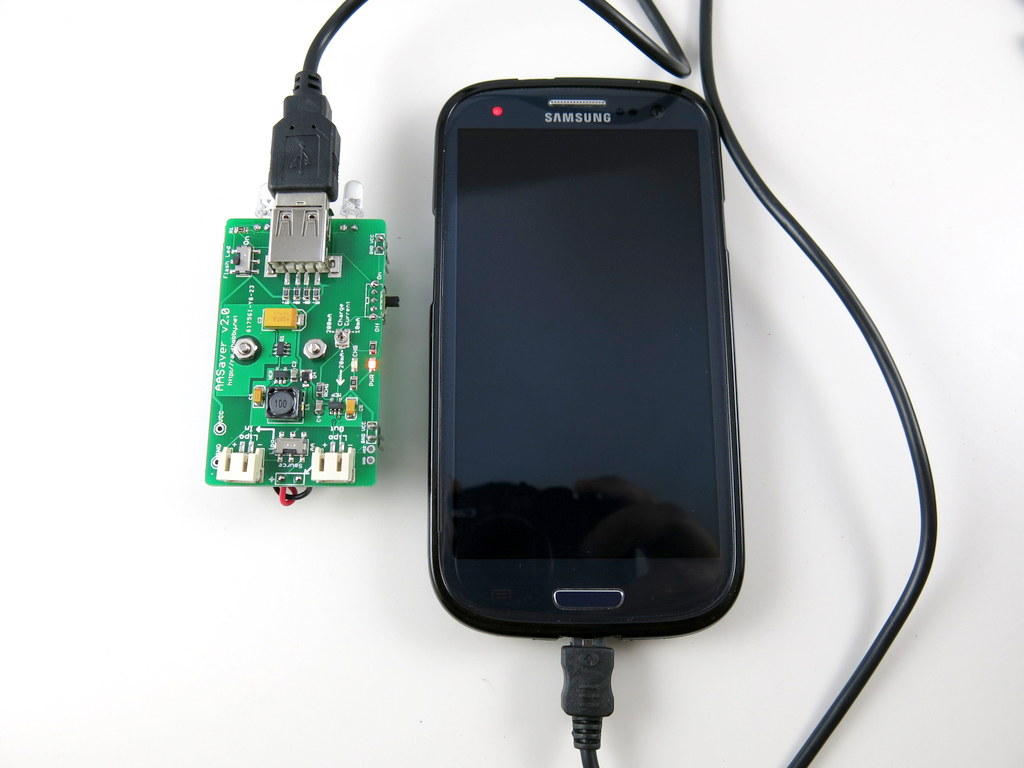
Using a fresh pair of batteries, the circuit can provide up to 500mA charging current @ 5V output, which is sufficient for most USB devices. Also, empirical results show that with a fresh pair of batteries, you can charge the iPhone and the Samsung Galaxy S3 phone up to 20% to 25%. This is not a whole lot, but is good enough as an emergency charger, since AA batteries are really easy to get at convenience stores.

Now, there is a tricky question: since the hallmark of the AASaver is to save old AA batteries, can I use old or even almost ‘dead’ AA batteries for USB charging? The answer is mostly NO. Well, there is no magic: most USB devices require a certain amount of charging current in order to charge properly. Mobile phones are particularly power hungry. To provide 100mA @ 5V output, the AA batteries need to output at least (100mA x 5V) = 0.5 Watt power, and usually more to account for the non-perfect efficiency of the boost converter. Depending on the battery condition, you may or may not be able to draw that much power from a pair of AA batteries — for fresh batteries, no problem; for close to depleted batteries, almost certainly no. Technically, the problem with old batteries is that as soon as you start to draw higher current, the voltage of the battery will drop, and so the boost converter will start sucking more current from it, causing the voltage to drop further. At some point, the boost converter will not be able to maintain a regulated output voltage, hence it will stop charging.

What if you really want to dump the juice from old AA batteries to your phone? There is actually a solution, and you should keep reading below.

Step 6. LiPo Charging

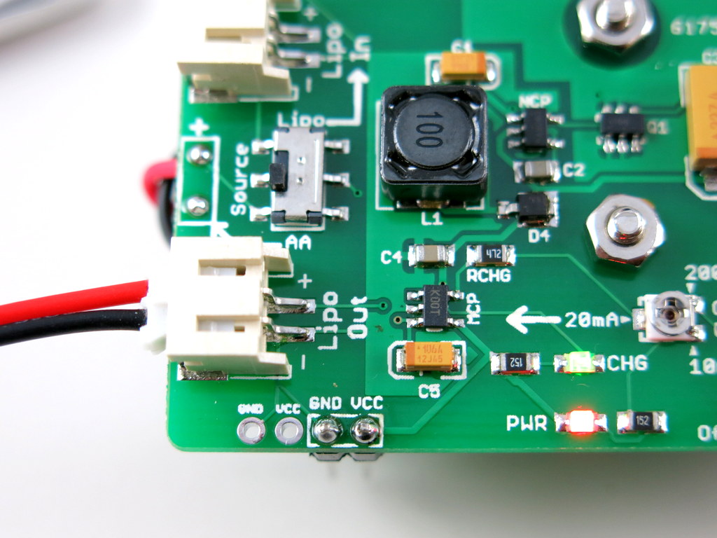
In addition to USB charging, one of the new features of the AASaver 2.0 is LiPo charging. If you have a 3.7V LiPo battery (we carry an inexpensive 700mAH LiPo battery at Rayshobby Shop), you can plug it in to the LiPo Out jack. This allows you to charge the LiPo battery from AA batteries with an adjustable charging current (from 10mA to 200mA). Once the battery is charging, you should see the green Charge Indicator LED light up.

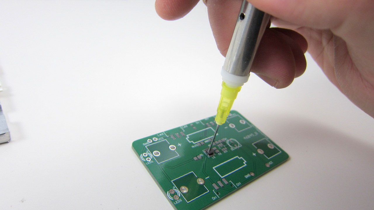
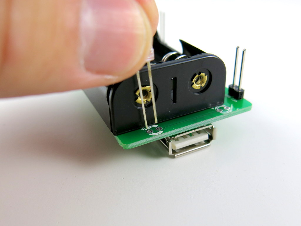
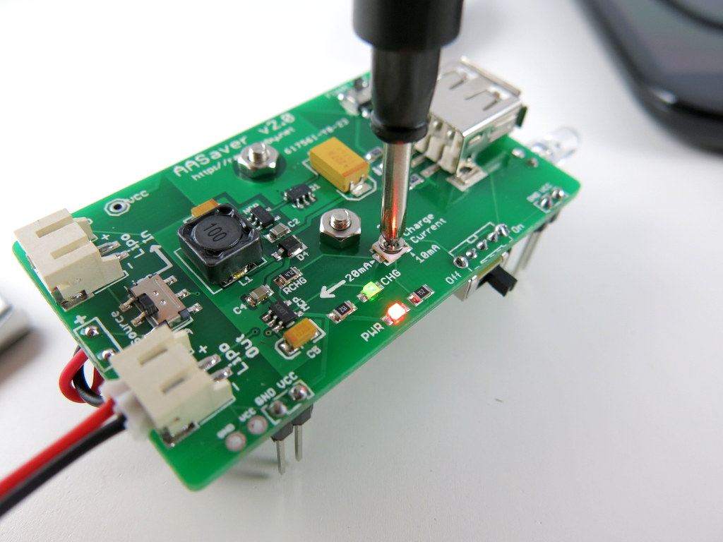
To change the charging current, use a small screw driver to gently rotate the trimmer (SMT POT). The trimmer is very fragile, so be careful when adjusting it. The flat side of the trimmer top is the tail, and the opposite side is the head. The charging current is indicated by where the head is pointing to.

How does the adjustable charging current help? As I described above, the issue with old batteries is that they cannot provide much output current. But they should still work if you ‘dump’ the power slowly. For example, they probably can’t provide 100mA output current at 5V, but they are probably good with 20mA current at 5V. So the trick is to dump the power slowly into a LiPo battery. This is analogous to having a water pipe with very limited capacity: you can’t draw water from it at a high speed, but you can let it drip slowly into a bucket (in this case the ‘bucket’ is the LiPo battery). Then later you can dump the water from the bucket at a much faster rate.

So all in all, if you have an old pair of AA batteries, you can’t charge USB devices directly. But you can still use them to charge a LiPo battery at a slow rate. To do so, adjust the trimmer so that the green indicator LED will remain on. If the LED goes off, it mean either the charge current is too high, or too low. So adjust the trimmer to keep it on. As you will see in the next step, with the LiPo battery, you can then charge USB devices with much ease.

IMG_2999IMG_3002

Step 7. Using LiPo Battery as Power Source

To use a LiPo battery as the power source, simply plug it in to the LiPo In battery jack, then make sure that you turn the Source Selector Switch up to point to LiPo In. This selects the LiPo battery as the power source, and everything else works the same way as before.
IMG_3000


All right, this is the end of the story. I know this post is very long, but most of it will be moved to the AASaver Homepage after I refine the text and hear back comments and suggestions from users. If you are interested, please place an order for the AASaver from the Rayshobby Shop. We have a limited amount right now and more stock will become available in the upcoming weeks.

Questions and comments? Post them below or on the Rayshobby Forum.


New Development PCB in the Mail Today

Yup, I opened my mail box and found the lovely purple envelope from OSHPark. What’s in it?
IMG_2720IMG_2721

Ah ha, it’s the new AASaver 2.0 prototype PCB. I can’t help getting my hands on it, so I quickly assembled two. Here is what the assembled board looks like (without and with AA batteries):

IMG_2722IMG_2723

AASaver 2.0 is sort of a ‘mega’ version of AASaver 1.0: like 1.0, it takes two AA batteries and serves dual functions as both an LED flashlight and breadboard power supply. But it can do much more. First of all, I’ve added a LiPo charger circuitry so that you can use two AA batteries to charge an external LiPo battery:
IMG_2728IMG_2726

I’ve also added an SMT potentiometer (trimmer) to adjust the charge current (see the picture on the right above), anywhere from 20mA to 100mA. This is not a random addition — there is a good reason to have this feature, which you shall see in a minute.

Another BIG addition is the functionality to charge USB devices like cell phones. Yup, you heard it right: there is a built-in type A USB receptacle that allows you to plug in a USB charging cable to add juice to your phone, MP3 player etc.

IMG_2725

So this is similar to Adafruit’s MintyBoost, except that there is a catch: on MintyBoost, you use a pair of fresh battery to charge the phone, but with AASaver the whole point is to harvest the remaining energy in used or old batteries. How does this affect anything? Well, used batteries typically cannot supply a high amount of current, so you can’t use them directly to charge the phone — it simply won’t provide enough current to charge. The trick is to dump the energy slowly into a LiPo battery, then charge the phone through the LiPo battery later! Essentially the LiPo battery serves as a ‘water bucket’, which accumulates charges slowly (like water drops), so that even used AA batteries can charge it; once the ‘water bucket’ has accumulated enough charges, it can dump the ‘water’ at much faster rate. This is the same idea as how solar chargers work: solar cells are too weak to charge phones directly, but you can build up the charges by leveraging a battery. Now you see why there is a built-in LiPo charger!

The picture below shows where the LiPo battery should be plugged in when you want to use it to charge USB devices. In sum, if you have a fresh pair of AA batteries, you can charge USB devices directly; otherwise you first charge the LiPo battery with a controllable charging current (20mA recommended), then use the LiPo to charge USB devices. The circuit of AASaver 2.0 accepts either AA or LiPo as the source of its boost converter, and directs the boosted 5V to either USB port, or LiPo charger, selectable through the ‘Target’ switch at the right-end of the board. On top of these, there is a separate switch for turning on the flashlight LEDs, and there are pin headers spaced appropriately to match a standard breadboard, so you can use it as a battery-based breadboard 5V power supply. As you can see, it has a load of new features to provide better and more flexible ways to save your AA batteries 🙂

IMG_2727IMG_2728

IMG_2727IMG_2724

The Making of the AASaver

A few weeks ago I received a new batch of the AASaver PCBs at home. I thought, now that I am fairly experienced, it would be interesting to document the process of how I assembled the circuit boards. As you will see below, my assembly setup is manual and is nowhere near the capability of making more than a hundred boards at a time (for that I would outsource the assembly to a professional company). Still, it’s reasonably efficient such that I can enjoy the process of making without losing my mind or temper :).

IMG_2264


Step 1. Stenciling

AASaver is designed with all surface mount components. So the first step is to apply solder paste by using a stencil. I used my recently purchased laser cutter to make a stencil out of a Kapton film sheet ordered from Amazon. There are plenty of online tutorials on how to use a laser cutter to make solder paste stencils, so I won’t repeat them here. If you don’t own a laser cutter, you can easily make a stencil using copper sheet with the standard toner transfer and etching method. The tutorial can be found in my previous blog post here. Before I had the laser cutter, I have always used home-made copper stencils, and they work just as good.

IMG_2265IMG_2300
(Left: stencil made from Kapton sheet; Right: stencil made from copper sheet with home PCB method).

Next, I used old PCBs to make a 3-sided frame that fits the PCB tightly. Then align the stencil with the PCB such that the holes and solder pads match together. I then taped the stencil to the frame for easy lifting up. This allows me to quickly insert and remove a PCB. Since the AASaver board uses fairly big components (0805 and SOT23-6), the alignment does not have to be extremely accurate. Now, before proceeding, you need some tools, including some gloves for hand protection and stencil wipes for cleaning (both are available from from Amazon),

IMG_2266IMG_2273

as well as solder paste (which I got from dealextreme.com) and a credit or membership card as applicator. Now, put a sizable amount of solder paste onto the applicator, and then start pressing it down onto the stencil. I usually do two passes: the first swipe leaves a thick layer of solder paste; then the immediate second pass scrapes the excessive paste off the stencil sheet. Use only medium pressure — you don’t need to press very hard. After stenciling, lift up the stencil and remove the PCB from the frame. Check the solder paste on each pad and make sure everything looks ok. If something is wrong, use stencil wipe to clean the solder paste off the PCB and start over.

IMG_2268IMG_2269

IMG_2270IMG_2272

The stenciling step doesn’t take much time. Once you are experienced, you can do it quite quickly: finishing 100 AASaver PCBs took me less than 20 minutes.


Step 2. Populating Components

The second step is populating components onto the PCB. This is the most time consuming step and you will probably want to take short breaks in between :). I used to do it with tweezers, which required a lot of patience. Recently I discovered a couple of tools that can help increase productivity quite a bit. The first tool is a vacuum pen. It comes with a portable vacuum pump, two plastic tubes, and a pen with several different needle sizes. This is available on eBay if you search ‘pick and place vacuum pen‘. Be careful that the unit only works with 220V (designed for Chinese market). So in order to use it with 110V, you need a step-up transformer, which I got from Amazon for about 7 bucks. Well, if you plug it directly into 110V power line, there shouldn’t be any damage, the pump probably just won’t start.

IMG_2274IMG_2275

The second tool I discovered is the SMT feeder. Again, this is available from eBay by searching ‘SMT feeder‘. These are similar to feeders found on automatic pick and place machines, except they are static and do not automatically advance the tapes. I made some labels to help me remember the components on each line.

IMG_2276IMG_2277

With these tools, placing components is much easier than using tweezers: I no longer have to dump components out of the tape, or flip components to face up, or spend a lot of time adjusting the orientation of the components. Such a time saver :).

So how do you use the vacuum pen? Notice that on the side of the pen there is a small hole. When you cover the hole with a finger, it creates vacuum suction pressure through the needle of the pen, which allows picking up components. Then when you remove your finger, the air flows through the hole, and releases the component from the needle. I typically use my index finger for this.

IMG_2279

To demonstrate: first, get the needle close to a component and cover the hole; then pick up the component (as long as your finger covers the hole, the component won’t fall off); finally, carefully approach the PCB, press down the component to where it should be placed, and release the finger. The placing step definitely requires some practice. You can use your other hand to help stabilize the movement and the ‘touch-down’.

IMG_2280IMG_2281

IMG_2282IMG_2283

The first few times I used the pen, I was shocked at how poorly the components were placed. I felt it’s a complete piece of junk. But then as I used it more, I realized that I do get more experienced with practising (feels kind of like playing a video game :). Anyways, now I can place components at pretty good speed and accuracy. Practice maker perfect. Note that sometimes you need to change the orientation of a component, and that can be done by simply rotating the PCB around with your other hand. Here is another example of picking and placing an SOT23-6 component, and lastly a picture of the fully-populated board:

IMG_2286IMG_2287

IMG_2288IMG_2284

These are 25 boards that have components placed and ready to be toasted:

IMG_2290


Step 3. Reflow Soldering

The next step is the fun step, which is the ‘cook’ the PCBs so that the components will be reflow soldered onto the boards. I used to do this step with a toaster oven and a digital thermometer to monitor the temperature. Because I was lazy, I didn’t implement any sort of feedback control. As a result, there were a couple of times that I ‘over-cooked’ the PCBs till they burned and smelled terribly. So I decided to buy a real reflow oven. The one I purchased is model T-962A from eBay (which used to sell at ~$400 but is now more expensive). Note that its sister model T-962 is cheaper but also has a much smaller soldering area.

IMG_2241IMG_2247

This reflow oven does the basic stuff: it lets you select a pre-programmed reflow temperature profile, or program a custom profile if you want; it follows the selected profile quite accurately, by using an internal infared heating element, a cooling fan, and microcontroller-based feedback control; it also has a glass slit window on the front to allow you to monitor what’s happening inside the drawer. The user manual even describes how to use it to solder double-sided PCBs, which I haven’t tried yet.

IMG_2242IMG_2245

The oven also has its drawbacks: the standard profile takes 7~8 minutes to finish one cycle of reflowing, which is not very fast but perhaps can be accelerated using a custom profile; also, the heating is not entirely uniform — the area close to the boundary is cooler than the center, causing PCBs placed nearby the boundary to be poorly soldered. But once I am aware of these limitations, I can cope with them.

One important thing to keep in mind is that you should place the reflow oven outdoors. Even with lead-free solder paste, the exhaust from the reflow process is unpleasant at least, and probably harmful to your health. So keep it out of your living area.

Once the reflow is done, I get back a tray of freshly baked ‘cookies’. Satisfied 🙂 Take a close look at the PCBs and see if everything looks ok. Especially check if there are any un-soldered paste. If so, put them back and bake again.

IMG_2291IMG_2293


Step 4. Testing

We are not done yet, so don’t bite. The last step is testing, to make sure the circuit board functions as expected. First, perform a quick visual examination. Occasionally components may drift off its position, probably due to insufficient solder paste. These are easy to fix with a hot air gun or even a standard soldering iron. To facilitate testing, I built a simple rig using an existing AASaver PCB and some pogo pins I got from eBay. Here is my setup:

IMG_2295IMG_2298

Because AASaver is a regulated voltage booster, the main things I need to test are whether its output voltages are within spec (5V and 3.3V), and whether it maintains the voltage levels (within 5-10% tolerance) under a given current load (320mA). So my test setup includes a multimeter, AA battery holder, and a power resistor to produce the required current load. If the board passes the test (i.e. outputs and maintains the designed voltage levels with load), it will be put into the ‘success’ bin; otherwise, it will be put into the ‘to-be-fixed’ bin for further checking. For a simple board like AASaver, the success rate (yield) is close to 100%.

IMG_2296IMG_2297

This is a picture of a fully-assembled AASaver in action. It takes two AA batteries, new or used, and can function as an LED flashlight as well as breadboard power supply with switch-selectable 5V and 3.3V output.

IMG_2299

That’s all. Feel free to leave your comments, questions, and suggestions. Thanks!


‘Sewing’ Wearable LEDs using Wire Wrap Wires

This week I am helping my school to organize a wearable electronics event for undergrads. Since none of us has done this before, the biggest question is to find out how to sew LEDs and other electronic components onto clothes. We ordered 2 spools of conductive threads, but shipping is a bit slow. While waiting for the order to arrive, I am thinking about alternative options to make wearable LEDs. Looking around my toolbox, I found some wire wrap wires. These are very thin, 30AWG wires typically used for wire wrapping. I was curious if it’s possible to use these thin wires for ‘sewing’ electronics onto fabric and clothes. After experimenting with it a bit, I found it is actually a feasible method. Check my end result first:

How does this compare to conductive thread?

  • Pros
    • No needle required, because the wire is stiff enough to go through fabric by itself.
    • Solderable.
    • Available in many stores and relatively cheap.
  • Cons
    • May break if stretched too much, again because the wire is stiff.
    • Can form small curls during sewing if not careful.

Video demo:

So how does this method work? Just follow my illustrated examples below:

First, get some 30AWG wire wrap wires,. These can be found in many stores (Sparkfun, Digikey, RadioShack etc). Use a wire stripper to strip the plastic exterior. You can also get 28AWG stringing wires (used for beading) available from craft stores. These wires are un-insulated, so you don’t even need to strip them.
Next, pick the fabric or textile you want to sew LEDs onto. I happen to have this awesome Make T-shirt. So let me use that!
Sketch your design with a chalk. I am going to have a string of LEDs connected in parallel along a heart shape. Here is my sketch. Not too bad.
Cut a piece of stripped wire, about 20 inch long. At one end, make a small knot and tighten it.
Hold the other end using your thumb and index finger, and push it through the fabric, just like how you would use a needle. Since the wire is quite stiff, it can penetrate fabric quite easily.
Follow your sketched pattern and move the wire forward, just like how you sew normally. When pulling the wire out, be careful not to form small curls. Use your finger to keep the wire as smooth as possible. Watch the video above for demonstration.
This is the outer layer of the heart shape.
On the inner side of the fabric, use an electric tape to fix the wire, and also to avoid shorting it with other wires.
One advantage of using the wire is that you can solder electronic components directly onto it. But if you want to avoid soldering, you can still use the wire to sew the component leads to the fabric (in the same way as conductive thread). In this image, the upper lead of the LED is sewed using the wire (without soldering), and the lower lead is soldered.
Now the inner layer is also finished. I didn’t draw a sketch for the inner layer, so it’s not perfectly parallel to the outer layer 🙁
Now I will solder LEDs onto the two wires. All LEDs are connected in parallel. The outer wire corresponds to positive lead, and inner wire negative.
A good way to keep everything organized is to first prepare all LEDs: bend their leads, and cut the negative leads short. This way, you won’t forget which lead is positive!
Try to keep an even spacing between LEDs, and fix them with a small amount of solder. After this is completed, connect the two wires to a battery to test if all LEDs are working.
Now use a wire cutter to cut all excessive leads. I actually like the spikes in the previous image. Looks more artistic :).
To provide programmable LED patterns, I use an Arduino Pro from Sparkfun. I sewed it onto the bottom of the shirt using normal threads.
I use Arduino Pin 11 to provide PWM control. Since there are 18 LEDs connected in parallel, driving them together requires a current that exceeds the limit of a single IO pin. So I use a BS170 MOSFET to switch the LEDs directly from power supply.
Here I am, wearing the Make T-Shirt customized with an LED heart! The LEDs are programmed with three modes: constant on, flashing, and fading. See the video above for demo. Enjoy!

Fun with Flashing LEDs on a Heavy Snowstorm Night

Last night, a heavy snowstorm mixed with strong winds hit Massachusetts. Many cities lost power, due to fallen trees and broken power lines. Snow in October? Rare and totally unexpected. When I woke up this morning, I found huge tree branches fallen everywhere. Driving through any road requires special attention. This is a picture of a tree in front of my office building that got split in half:

The damage is clearly much more serious than the much anticipated Hurricane Irene in August, which caused very little harm. Even now I still don’t have power at home, and more than 60% of the city is out of power. Looks like I might have to stay at the office for tonight…

Anyways, due to the power outage, the web server went down for almost an entire day. I got a couple of emails about what’s happening. The good news is that it’s now back online, so that’s a relief.

So what did I do last night? Well, most of the night we were just sitting in the dark, with candles, and chatted. That’s not the whole story though. The rest of the time, I was…having fun with flashing LEDs! How come? Well, we had planned a small gathering with friends to carve pumpkins together, and I came up with the idea of making a few flashing LEDs to decorate the pumpkins. I was lucky enough to finish making two pairs of them before the power went out. We didn’t have any pumpkins to decorate, but I put one pair on a plush Totoro, and made an angry, dark Totoro. Check it out (sorry that the video is really short because my phone was running out of battery!):

So how did I make the flashing LEDs? It’s by using a circuit called the multivibrator. Sounds funny? Well, hold your thought… The multivibrator is a very basic oscillator, involving only two transistors, two capacitors, and four resistors. In the next blog article, I will explain how to make it and the principles behind it. There is nothing particularly novel, and most people would probably go with a 555 rather than transistors. But it’s really fun to learn how such a basic circuit works. Stay tuned!

Cheap 16×2 LCD with LED Back light

Recently I was looking for a cheap 16×2 LCD, and I found several interesting models on eBay that come with great price. I purchased one with blue backlight. The total is only $3.49 including shipping. The product was shipped from Hong Kong, so it took about 2 weeks to arrive. Here are two images of the front and the back:

The model number is 1602a and the spec is easy to find online by searching the model number. It’s HD44780 compatible, so it can work directly with the Arduino LiquidCrystal library. The blue LED backlight looks quite pleasant. Here is an example:

One downside is that the back LED is a bit noticeable (see the glow on the right edge of the display); also, the text will be almost completely invisible if the LED is turned off, so the LED has to remain on, consuming more power.

Making it work with Arduino is straightforward by following the LiquidCrystal example. I made small changes to the pin assignment. Here is what I did: LCD RS, Enable, D4, D5, D5, D6 pins are connected to Arduino pin 12, 11, 8, 7, 6, 5 respectively. Normally the display contrast (V0) pin of the LCD is connected to a potentiometer in order to adjust the contrast voltage. After some experiment, I found that the desirable voltage is about 0.65V, which can be supplied by the forward bias voltage of a standard diode, such as 1N4148.

In order to control the back LED brightness, I made use of a transistor (2N3904) and Arduino’s PWM (pulse width modulation) to adjust the effective voltage supplied to the LED. The transistor serves as a current sink, and its base is connected to Arduino pin 10 to apply PWM control. This is very standard design, refer to the schematic below. With this, I can easily control the brightness of the backlight. Just to demonstrate it, I wrote a simple program based on the Scroll example provided in Arduino. The program scrolls text left and right, meanwhile I use a timer interrupt to brighten and dim the backlight. See the video below.

Some ghosting artifacts are noticeable as the words move left and right. The video probably exemplified them, the actual LCD looks better than the video.

Update: It’s ok to connect Arduino pin 10 directly with LED- or LED+ to supply the PWM signal without using a transistor. Arduino’s I/O pins can source or sink more than 20mA of current, which is sufficient to drive the backlight LED. Other microcontrollers might not be able to do so directly from their I/O pins.

In summary, this is an decent and inexpensive LCD, which works nicely with Arduino. Right now it occupies 7 Arduino pins (1 of them has to support PWM), but this number can be reduced to 3 by using a shift register. The schematic and source code for the example program are attached below. Comments and suggestions are welcome!

Download Arduino source code lcd1602a.pde.