Fun with Flashing LEDs on a Heavy Snowstorm Night

Last night, a heavy snowstorm mixed with strong winds hit Massachusetts. Many cities lost power, due to fallen trees and broken power lines. Snow in October? Rare and totally unexpected. When I woke up this morning, I found huge tree branches fallen everywhere. Driving through any road requires special attention. This is a picture of a tree in front of my office building that got split in half:

The damage is clearly much more serious than the much anticipated Hurricane Irene in August, which caused very little harm. Even now I still don’t have power at home, and more than 60% of the city is out of power. Looks like I might have to stay at the office for tonight…

Anyways, due to the power outage, the web server went down for almost an entire day. I got a couple of emails about what’s happening. The good news is that it’s now back online, so that’s a relief.

So what did I do last night? Well, most of the night we were just sitting in the dark, with candles, and chatted. That’s not the whole story though. The rest of the time, I was…having fun with flashing LEDs! How come? Well, we had planned a small gathering with friends to carve pumpkins together, and I came up with the idea of making a few flashing LEDs to decorate the pumpkins. I was lucky enough to finish making two pairs of them before the power went out. We didn’t have any pumpkins to decorate, but I put one pair on a plush Totoro, and made an angry, dark Totoro. Check it out (sorry that the video is really short because my phone was running out of battery!):

So how did I make the flashing LEDs? It’s by using a circuit called the multivibrator. Sounds funny? Well, hold your thought… The multivibrator is a very basic oscillator, involving only two transistors, two capacitors, and four resistors. In the next blog article, I will explain how to make it and the principles behind it. There is nothing particularly novel, and most people would probably go with a 555 rather than transistors. But it’s really fun to learn how such a basic circuit works. Stay tuned!

OpenSprinkler Backup Battery Option

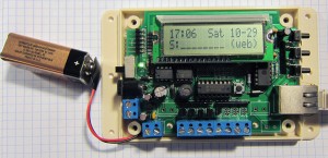
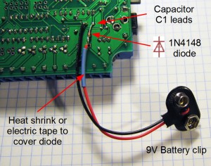
Matt asked about the option of having a backup battery for the OpenSprinkler, so I prepared a short blog article to show how it can be done. Basically, you just need to get a 9V battery (or any battery that can provide 6V or above voltage), connect the positive lead with a diode (such as 1N4148) in forward direction to the positive lead of C1 (100uF capacitor), and the battery’s negative lead to C1’s negative lead (which is ground). See pictures below for illustration. Make sure to use a heat shrink or electric tape to cover the diode after it’s soldered.

With the backup battery, the microcontroller (and hence the time) will keep running when there is power outage. Once the main power is back on and the Ethernet connection is available, the controller will be able to obtain more accurate time through NTP sync (the default setting is one sync per hour).

But there is a catch (as always!), which is: the controller draws a lot of current (~140mA), so with a standard 9V battery (the typical capacity of which is 560mAh) it can only last for about 4 hours.
The large current draw is mainly due to the Ethernet controller. One solution is to use a higher capacity battery (such as AA or Li-Poly). Another option is to put the Ethernet controller to sleep when it cannot get a connection. This can be done in software. In any case, there is now a temporary solution for battery backup, and a better option will be provided in the next hardware update.

OpenSprinkler v1.0 Known Issues Documented on the F.A.Q. Page

Thanks for everyone who ordered the initial batch of the OpenSprinkler controller. A couple of issues have been reported and documented on the F.A.Q. page. If you are learning to use the controller, be sure to check that page.

The most recent bug turned out to be caused by the Arduino’s shiftOut function (thanks Matt for discovering the problem initially). This bug has now been reported to the Arduino forum. The symptom is that whenever you open the sprinkler zones, station #8 always turns on, and will remain on even if you stop the controller’s operation. This is caused by the shiftOut function missing a rising edge for the shift register. You can simply re-program the microcontroller to fix this bug. Orders sent on or after Oct 23, 2011 have already included this bug fix.

Use Arduino to Interface with a Remote Controlled Power Switch

Update: check out the RFToy — an easy-to-use standalone gadget to control remote power sockets. Also, support for remote power sockets have been added to OpenSprinkler firmware 2.1.1.

For a while I’ve been looking for a way to switch household power line (110V) devices. One of the simplest options is to use a relay that is connected to the power line. This is easy in concept but quite dangerous to work with. You don’t want to accidentally touch the power line wire and shock yourself. A much better option is to use the powerswitch tail, which insulates the relay and the relevant circuity inside a plastic enclosure, leaving only two MCU pins to interface with. Much safer. But you still have to run wires between your MCU and the power socket. I am more interested in an wireless option.

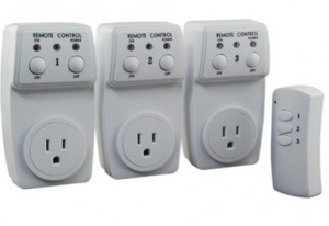
Recently I purchase a set of remote controlled switch sockets from Amazon. It comes with one remote and three sockets, each of which can be individually switched. The whole package is quite cheap. The way this works is that you plug the sockets into the wall, and when you press a button on the remote, the corresponding socket will switch, thus turning on or off the device connected to the socket.

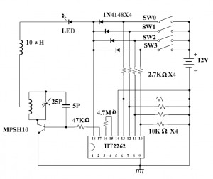
I took apart the remote control and found that the circuit is quite simple. It’s based on an HT2262 remote control encoder and a 434 MHz transmitter circuit. In fact, the schematic of the circuit is well documented in the datasheet of the encoder:

From the schematic, it’s quite clear that when a button is pressed, the input voltage is fed to one of the encoder pins (as well as the VCC pin of the encoder). Then the encoder will send the signal to the RF transmitter circuit. The RF signal will be received at the power socket side and decoded. Very simple. Now, to use my Arduino to interface with this power switch, all I need to do is to simulate a button press by sourcing a positive voltage to wires labeled SW1, SW2, SW3 etc. It turns out that the HT2262 can work with a fairly wide range of voltage: from 4V to 18V. Clearly the 5V output from an Arduino IO pin falls within the acceptable range. So I can simply connect those wires individually with Arduino I/O pins, and write a program that outputs HIGH momentarily when I need to switch a device. The only downside is at 5V the transmitting range is limited. The higher the input voltage, the longer distance it can transmit. So a more flexible design is to have a ‘source’ driver to supply higher than 5V to the encoder.

Update: check out the RFToy — an easy-to-use standalone gadget to control remote power sockets. Also, support for remote power sockets have been added to OpenSprinkler firmware 2.1.1.

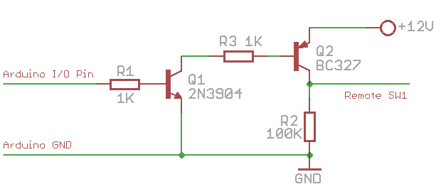
This can be done by using a transistor based high-side switch. Here is a schematic:

Basically, when the IO pin outputs low, transistor Q1 (NPN) turns off, and its collector is in high impedance status. Hence Q2 (PNP) is also off. Now, when the IO pin outputs high, Q1 conducts, driving the gate of Q2 low. Therefore Q2 also conducts, sourcing +12V voltage to the encoder. The reason to use such a high-side driver is to be able to switch a high voltage (>=12V) using a relatively low-voltage (<=5V) control signal from the MCU.

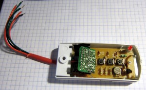
I implemented this method on a small proto-board. Since the remote control has 3 buttons, I made 3 copies of the above high-side driver, and the entire circuit fits nicely inside the remote control cover. I soldered five wires out: +12V, GND, and three control wires. A picture is shown on the left.

With this modification, I can now switch power line devices such as home lights and heaters using a microcontroller. Better, I can connect the remote control with my OpenSprinkler Controller, thus I am able to control power line devices through a web interface. The video below show a demo. Enjoy!