Recent News and Updates on ESPToy

This post is a quick update on the recent development of ESPToy. I made a video and here is a brief summary of what I covered:

  • New version 1.22 which has added LiPo battery jack and charger (see previous announcement here).
  • New startup demo with more polished user interface and better reliability across browsers.
  • Overstocked ESPToy printed circuit boards (PCBs) available at Rayshobby Shop.
  • Comparisons with NodeMCU and Adafruit’s upcoming Huzzah.
  • Power socket modified with ESPtoy.

Here are some snapshots.
esptoy_update_startupesptoy_update_compare

esptoy_pcb_frontesptoy_update_powersocket

Here is the video. Enjoy!

Introducing RFToy 1.0

Today I am introducing the first version of RFToy — an Arduino-compatible gadget for interfacing with Radio Frequency (RF) modules. First, let me show you a few pictures of RFToy and a video introduction:

IMG_0419IMG_0428IMG_0426
IMG_0427IMG_0431


RFToy is available for purchase at Rayshobby Store.


Features
  • ATmega328p @ 3.3V, 8MHz, with CH340G USB-serial converter and Arduino bootloader.
  • Programming in Arduino using the on-board mini-USB port.
  • One 128×64 OLED display, three tactile buttons.
  • 20mm coin battery holder, and slide switch to select between USB or battery power.
  • Pin headers for plugging in 433/315 MHz RF transmitter and receiver modules, and MOSFET power switches for them.
  • 3.5mm audio jack to output receiver signals to a computer’s line-in port, to monitor RF waves.
  • Pin headers for plugging in nRF24L01 transceiver.
  • Pin headers for connecting external components and/or breadboard experiments.

So in essence, RFToy is a 8MHz Arduino with buttons, OLED display, battery holder. It’s compact (1.5″ x 2.3″) and it’s suitable for a variety of projects involving RF modules.

rftoy_annotated


Demos

As shown in the video above, I’ve written a couple of examples to demonstrate the basic features of the RFToy.

  • RF Recorder: this demo shows how to use RFToy to decode signals from the remote control of a typical wireless power socket, store the decoded signal in EEPROM, and play it back to simulate the remote control. You can store up to 7 different signals, allowing you to control up to 7 power sockets. The demo is based on the RCSwitch library, and it has a basic UI using the OLED display and buttons.
  • Wireless Temperature Sensor: this demo uses a pair of RFToys — one RFToy has a thermistor (connected to analog pin A1) and sends out the temperature reading periodically through its 433MHz transmitter; the other has a 433MHz receiver, and displays the received value to the OLED. This demo is based on the VirtualWire library, and uses the watchdog timer and power-down sleep to save battery life when the sensor is not transmitting data. A variant of this demo is also provided using a pair of nRF24L01 transceivers and the Mirf library.
  • Interfacing with Off-the-Shelf Wireless Sensors: previously I’ve written several blog posts about using Arduino to interface with off-the-shelf wireless temperature, humidity, rain, and soil moisture sensors. Since these sensors all work in the 433MHz frequency band, these demos can all run on RFToy, with sensor values displayed onto the OLED.

With the built-in buttons, display, and Arduino compatibility, there are tons of other projects you can build with RFToy.


User Manual

RFToy is open-source. You can check out its Arduino library code at http://github.com/rayshobby/rftoy, and hardware design files at http://github.com/rayshobby/rftoy-hw. Some technical details are provided below:

Note: the content on this page is published under Creative Commons Attribution-ShareALike (CC BY-SA) 3.0 License. Content reuse is allowed. If you have a project/product based on RFToy, please acknowledge my contribution. The software code and hardware design are published for educational purpose.


Purchase Link


Reflow Toaster Oven with Bells and Whistles

A reflow oven comes in handy when you work regularly with SMT circuits. I’ve had the T-962A reflow oven for about a year now. While it has worked reasonably well, recently it has started showing some signs of aging. First of all, the total reflow time is quite long, about 15-16 minutes. This is really slow. Worse even, occasionally the internal temperature sensor would have a hiccup and the boards would come out under-heated or over-heated. Also, I hate the built-in buzzer, which produces a very loud, high-pitched beep when reflow is completed. This is very annoying — since I keep the reflow oven outdoors, I didn’t want my neighbors to think the beep is my fire alarm. So it’s time to find an alternative / backup solution.

After some online research, I’ve decided to build a reflow toaster oven using an Arduino-based controller. Toaster oven is cheap and provides better, more even heating than a hot skillet. I know toaster oven reflowing has been blogged about everywhere, but I do want to give my version some bells and whistles to provide more convenience. For example, I typically keep the reflow oven outdoors on my porch while working in the basement. So I’d like to receive a remote notification when reflow is complete (no loud beep please!). Also, I’d like an automatic way to open the oven door and blow air into the oven to accelerate the cooling time. For remote notification, I’ve decided to use an 433MHz RF transmitter to send signals to a remote power socket. I have a lamp connected to the power socket, and this way I will get notified when reflow is done. For faster cool-down time, I will use a servo tied to the oven door handle with a string — rotating the servo shaft can pull the door open. I will also put a second remote power socket connected to a circulation fan to blow air into the oven. Since I am using remote power sockets anyways, I am going to throw in a third one for the oven. This way all power line devices are controlled by power sockets, so there is no messing around with cutting cables etc. If you want better reliability, you can certainly use a relay or an SSR. I just decided to go with RF power sockets for the convenience.


Materials
Here is the list of materials I used:

IMG_3591IMG_3593IMG_3594IMG_3595
I have an existing set of RF power sockets and I don’t remember where I got them. But the link provided above looks similar, so they should work fine. A quick note: there are cheaper RF power sockets which only support toggling, but I would suggest getting the type that has separate on/off buttons for each channel, because you can know for sure whether the socket is on or off. Also, there are some types which work in the 315MHz frequency band. In this case, you need to get 315MHz RF transmitter instead of 433MHz.


Step 1. Temperature Probe
The reflow oven is a temperature-controlled device, so the first thing to do is to have the microcontroller sense temperature. The cheap kitchen thermometer is perfect for this: it has a thermistor (i.e. temperature-sensitive resistor) wrapped around a metal probe. Just open the thermometer, desolder the two wires, and extend the wire length by soldering two pieces of longer wires. I also used some hot glue to fix the joints so they they won’t move around and break.

IMG_3597IMG_3598IMG_3607IMG_3596

Next, measure the diameter of the temperature probe (mine is about 0.147″), and at the back of the toaster oven drill a hole that’s slightly bigger (I used 5/32 drill) than the probe size. The hole should be located at roughly a quarter to one-third on the height, so that when the probe is plugged in it would neither touch the top heating element nor the tray. Next, wrap a layer of Kapton tape around the temperature probe, and insert it through the hole, so that it stays tight in place.

The oven should be set to the highest temperature, convection, and stay on. This way we can bypass the oven’s internal control mechanism and instead use the microcontroller to turn heating on and off.
IMG_3599IMG_3602IMG_3603IMG_3606

For the microcontroller to sense temperature, just use the 2.32K resistor to form a voltage divider with the thermistor (i.e. probe). See the schematic on the right below. The divided voltage is connected to Arduino’s analog pin A0 for reading.

IMG_3608t_volt_divider


Step 2. Temperature Calibration
The next step is to perform temperature calibration. If you’ve got the same kitchen thermometer and 2.32K resistor as I have, you can skip this step. But if you have a different set, you need to perform a calibration step to find out the relationship between the actual temperature with the analog reading. To do so, I used an existing digital thermometer (my EX330 multimeter) to serve as reference. Insert its temperature probe to the oven and get the tip close to the center; then I wrote a simple Arduino program to print out analog values from A0 once every second. Turn on the oven to let it heat up. The temperature will rise, and the analog reading also rises.
IMG_3609IMG_3610IMG_3611

When it reaches about 210°C (Celsius), turn off the oven, and record the analog reading. Then do another reading when the temperature drops to about 170°C, and the last one when it drops to about 80°C. Basically 210°C is when we should stop heating (the temperature will climb up a little more beyond 210), 170°C is when the oven door will open and the fan will kick in, and 80°C is when the reflow is considered finished. My readings corresponding to these three temperature values are roughly 830, 790, and 360. These will be used in the Arduino program later.

IMG_3612IMG_3613IMG_3614


Step 3. Oven Door Opener
Next is a fun step. I built a oven door opener using a servo. The basic idea is to attach a piece of string between the servo and the oven door handle. Rotating the servo shaft will be able to pull the door open. To do so, I picked up some pieces of wood from HomeDepot and build a wooden frame. To make the whole assembly stable, the base of the frame should be sufficiently heavy. Then I secured the servo to the frame using some long #4 screws and nuts. Since the servo doesn’t come with a long shaft, I used a small piece of wood and attached it to the servo gear. This can extend the sweeping distance of the servo. Be careful not to make it too long though, otherwise you may overdrive the servo’s torque.
IMG_3620IMG_3621

The video below shows the servo in action. This is using Arduino’s built-in Servo example called Sweep. The servo’s three pins are connected to 5V, pin D9, and ground.


Step 4. Remote Power Sockets
The next step is to interface with the remote power sockets. I’ve written a previous blog post about this. Since then I have discovered the RC-Switch Arduino library. This is a very useful library that can automatically decode the signal patterns from most common remote power sockets. All that’s required is an Arduino and a RF receiver. I wired up my 433MHz receiver to the Arduino, and used the library’s receiver example to figure out the following binary code for my power sockets:

  • Channel 1 on: 010101010011000101000011; off: 010101010011000101000000.
  • Channel 2 on: 010101011100000101001100; off: 010101011100000101000000.
  • Channel 3 on: 010101010000110101110000; off: 010101010000110101000000.

Once the patterns are figured out, I can then connect a 433MHz transmitter to Arduino to simulate the remote control. This way I can reliably turn on and off each socket individually.


Step 5. Putting Everything Together and Testing
Now all the ingredients are ready, it’s time to put everything together for testing. The Arduino pin assignments are: temperature probe on analog pin A0, servo on digital D9, and RF transmitter on D10. The power sockets assignments are: toaster oven on channel 1, fan on channel 2, and lamp on channel 3. Since the controller will be used outdoors on the porch, I found an enclosure that can fit everything nicely inside. I also soldered a wire to the RF transmitter as an antenna to extend the transmission range. The power comes from an external 5V adapter. Please check the video at the beginning of the post for demonstration. The controller program source code can be downloaded here:

IMG_3622IMG_3623

With the capability of opening oven doors and blow air into it, the cool-down time is significantly faster. The total reflow time is about 6 minutes now, which is a lot better than 15 minutes before. That’s it, my reflow toaster oven with bells and whistles. It can certainly be improved by adding PID control, The hardware cost, everything included, is about $120. It’s inexpensive and pretty easy to replicate. Much better than my professional reflow oven!


OpenSprinkler Zone Expansion Board Upgraded to v1.1

One of the hallmarks of OpenSprinkler / OpenSprinkler Pi is the capability of expanding the number of zones. While the main controller can only interface with 8 zones, you can expand beyond 8 zones by daisy chaining Zone Expansion boards. Each expansion board adds another 8 zones. Because the zone expansion is implemented using shift registers, there is no hardware limitation on the total number of zones (although there is a software limitation due to the memory space required to store the information and data for each zone). This provides an economic way to implement a large number of zones. On commercial sprinkler controllers, zone expansion is relatively expensive, sometimes requiring you to upgrade to a new controller all together. On OpenSprinkler, if you need more zones, just buy more expansion boards. The software is designed to handle all zones in a consistent user interface.

Previously, the zone expansion board is based on the same PCB as the main controller, and they share the same enclosure. This makes it easy to use a consistent enclosure design for both. However, the zone expansion circuit is actually very simple (just a shift register, a couple of resistors, and eight triacs), so it’s no need to commission a PCB as large as the main controller for something that can be much smaller. So I’ve decided to give the expansion board an upgrade, to version 1.1, which uses a much smaller PCB footprint, and its own dedicated enclosure (based on Serpac WM011).

IMG_3017IMG_3014

The new version is just a little over half the size of the original one. So in the same amount of space you can almost fit two expansion boards. This is particularly useful for people who has a limited space to fit a main controller and one or more expansion boards.

In addition, the zone expansion cable has been upgraded to use a polarized connector. Specifically, the connector has a small bump at the top, which matches the notch on the cutout of the enclosure. This way, there is only one possible orientation to insert the cable connector, thus preventing incorrect orientation:

IMG_3011IMG_3013

The picture on the left above shows the polarized cutout on the expansion board, and the picture on the right shows a similar cutout on the upcoming injection molded OpenSprinkler enclosure. This can help avoid mistakes when inserting the expansion cable. A special note that this cable has different pin connections with the previous version of expansion boards. So you should NEVER use the polarized cable with previous versions of zone expansion boards, or you may risk damaging your main controller!

Finally, expansion board v1.1 has added a 10K pull-down resistor, which when coupled with OpenSprinkler 2.0, allows the main controller to automatically detect the number of zone expansion boards. This feature is already included in hardware design, but hasn’t been implemented in software yet. The basic principle is that the main controller has a 1.5K pull-up resistor, and each expansion board has a 10K pull-down resistor. When multiple expansion boards are linked together, the pull-down resistors are connected in parallel, thus changing the divided voltage. By using an analog pin (which is internally wired to the voltage division point), the controller can easily calculate how many boards are linked together. A very simple solution!

To conclude, here is a short summary of the new features on OpenSprinkler Zone Expansion Board v1.1:

  • Reduced form factor, and dedicated enclosure.
  • Polarized expansion cable connector.
  • Added pull-down resistor for automatic detection of the number of expansion boards.
  • Besides, the new expansion board retains the on-board PCB holes to fit one MOV per zone, and it works with both OpenSprinkler and OpenSprinkler Pi.

That’s all for the update. This new version is in stock and available for purchase at Rayshobby Shop. Same old price!

24VAC to 5VDC Conversion

Voltage conversion from 24VAC to 5VDC is quite useful, because a lot of home automation devices use 24VAC, including sprinkler solenoids, home surveillance systems etc. Having a conversion module makes it easy to use a single power supply, without a separate 5V adapter for your control circuit. There are plenty of resources you can find online about it. But these resources are rather scattered. So in this blog post I will summarize and discuss the common choices.


AC to DC Rectification

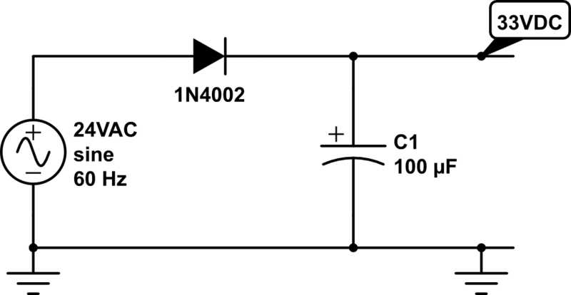
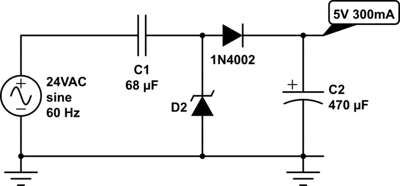
Before we begin, the first step is to have a rectifier that converts voltage from AC to DC. The common choices are half-wave rectifier (which requires just one diode) or full-wave rectifier (which requires four diodes). For simplicity, I will use half-wave rectifier as an example. The typical schematic of a half-wave rectifier is as follows:

half-wave-rectifier

It’s simply a diode followed by a capacitor to smooth out the rectified AC waves. As we know, diode only allows current to flow in one direction, so after the AC voltage passes through the diode, only positive voltage remains. The diode must be selected based on the maximum reverse voltage and the maximum current. One thing easy to forget is that when we talk about 24VAC, we mean the RMS (root-mean squared) magnitude of the voltage is 24V. Since AC voltage is a sine wave, the peak voltage is actually 24 * sqrt(2) = 34V, which is quite a bit higher. The maximum reverse voltage applied on the diode is therefore 34 – (-34) = 68V, which is when the AC voltage runs to the negative peak. So a diode with 70V peak reverse voltage is sufficient.

In practice, transformers that are rated 24VAC usually have a higher no-load voltage, which can vary between 26VAC up to 28VAC. This is typical, and the voltage is supposed to drop close to 24VAC under maximum load (i.e. the current rating of the transformer). As a result, when the circuit is powered on, the transformer can output a peak instantaneous voltage of up to 28 * sqrt(2) = 39.6V.

In the schematic above, I’ve picked a 1N4002 diode (70V reverse voltage, 1A current) and a 100uF/50V capacitor. These should work well for common scenarios. Note that the voltage output on the capacitor is approximately 34V – 1V (diode’s forward drop voltage) = 33VDC. Again, when the transformer is well below maximum load, the output voltage can go as high as 39.6V – 1V = 38.6V.

So next time if you see a power transformer rated 24VAC, after rectification, gives 39VDC, don’t be surprised!!


Now that we have a DC voltage, the next part is to step it down to 5VDC. We want it to be regulated, so that the voltage won’t fluctuate much. There are a variety of solutions:

1. Zener Diode

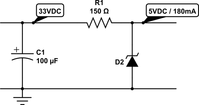
Probably the simplest solution is to use a Zener diode. As we know, a Zener diode can force the voltage across it to remain constant (break-down voltage) when it’s in the break-down condition. This condition is met when the current flowing through it (in reverse direction) is at least a few milli-amps (5mA typical) but less than the maximum current allowed (e.g. the diode’s power rating divided by its break-down voltage). For example, a 5V/1W Zener will remain in break-down condition when the reverse current is between 5mA and 1W/5V = 200mA. The typical schematic is shown as follows:

zener_regulator

Here resistor R1 is used for current limiting. Assume D2 is a 5V Zener diode, and the circuit on the right-hand side draws about 180mA current. R1 must be selected such that the current flowing through it is 180mA plus at least 5mA to keep D2 in break-down condition. So we have R1 = (33 – 5) / 0.185 = 150 ohm. Note that D2 should be rated at least 1W, because in case of open-circuit, it needs to absorb the entire 185mA without burning out.

Now let’s take a look at the power rating of the resistor R1. Since the current flowing through it is 185mA, the power is 0.185 A * 0.185 A * 150 ohm = 5.1 Watt. Wholly crap — this is gotta be a big resistor, isn’t it :). Well, this is the unfortunate drawback of a Zener diode based regulator, that is, it can waste a lot of power and require a bulky resistor. Fundamentally, it regulates the voltage by converting the voltage differential to heat. In this case, the voltage differential is quite big (33V vs. 5V), and the current draw is fairly large (180mA) too, so it ends up wasting a lot of power in heat.

Another drawback is that to increase the current draw, we must decrease R1. Otherwise, if the output circuit starts to draw, say 250mA, that will take D2 out of its break-down condition, and the output voltage is not regulated any more. So overall it is only suitable if the current draw is constant and small (e.g. tens of milliamps).


2. Linear Regulator

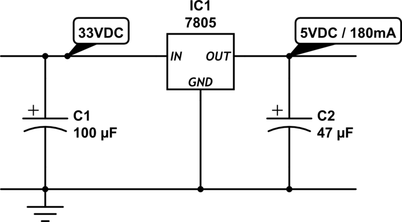
Another simple solution is to use a linear regulator, such as the popular 7805. The typical schematic is as follows:

linear_regulator

The circuit is quite simple, and the output current can vary across a wider range. However, linear regulator shares the same drawback with Zener diodes, that is, it fundamentally works by converting voltage differential to heat. As a result, it wastes the same amount of energy (5.1 Watt in this case) in heat. This is not only a matter of waste, but also it requires a large heat sink to dissipate the heat, otherwise the regulator will burn and smoke. So clearly not an efficient solution. In fact, the efficiency of a linear regulator is the ratio between the output and input voltages. In this case, it is 5 / 33 = 15.15%, which is very poor.


3. Switching Regulator

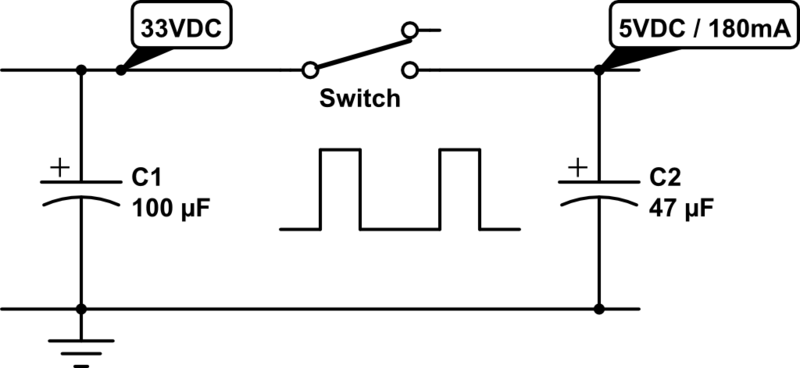
Now we have come to my favorite topic: switching regulator, also known as switching converter, or switch-mode power supply (SMPS). It uses transistors and a reactive component, namely inductor, to convert voltages much more efficiently. Ideally the switching converter works by simulating the following:

smps_ideal

That is, imagine there is an automated switch between the input and output. When the switch is turned on, it connects the input to output, and when it turns off, the input and output are disconnected. This essentially generates a square wave with 33V peak voltage, and the duty cycle is determined by the switch. Suppose the duty cycle is 15.15%, as long as the switching frequency is sufficiently high, at the output it would seem as if you have a constant voltage of 33 * 15.15% = 5V. That’s it, simple!

The main advantage of switching regulator is that since there is no resistive element, theoretically there is no energy loss at all, so the conversion efficiency is 100%! Of course in practice there will be some energy loss due to the imperfections of electronic components. Still, even at 75% efficiency, we are talking about a power waste of only (5V * 0.18A / 0.75) – (5V * 0.18A) = 0.3 Watt, much better than the 5.1 Watt waste you saw previously with a linear regulator.

The schematic above may look very simple. But it doesn’t tell the whole story. Implementing the switch is more complicated than you might think. That brings out the drawback of a switching regulator, namely cost and circuit complexity. It typically involves a transistor or MOSFET that functions as a digitally controlled switch, an oscillator circuit that generates a control square wave, a voltage reference and feedback module that monitors the output voltage, and finally a current sensing or thermal shutdown module that protects the regulator. That’s why switching regulators are typically provided as integrated circuits.

MC34063
Probably the cheapest and most widely used switching regulator is MC34063. The volume pricing (quantity 100+) is only 20 to 30 cents. Dave Jones at the EEVblog has a nice video tutorial about how to use MC34063. Also, there are a lot of MC34063 calculators you can find online, which will help you figure out the component values and parameters.

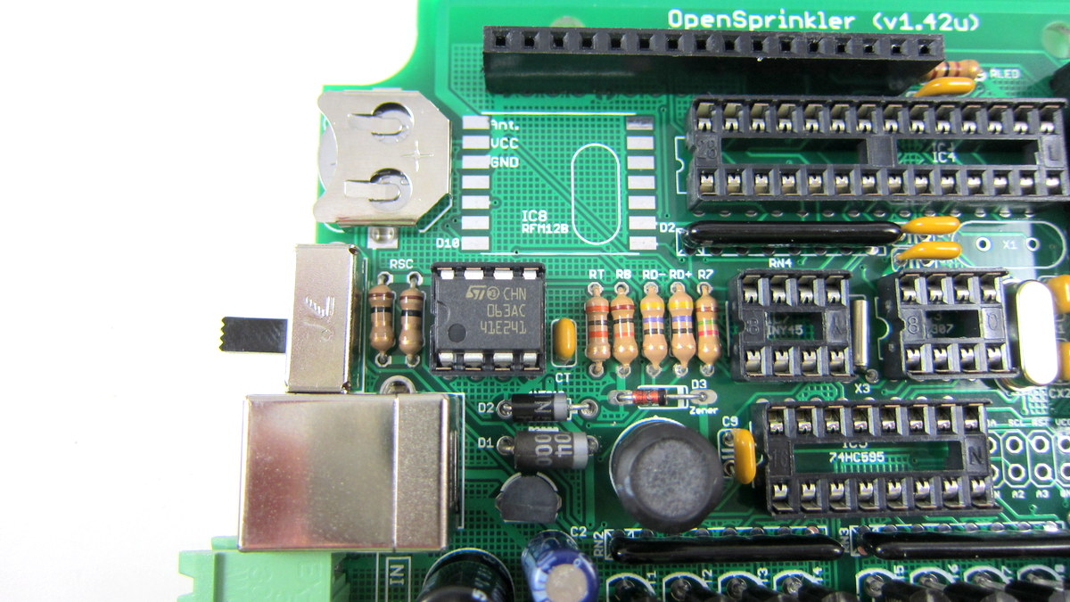
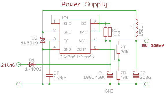
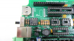
The schematic on the left below shows what I have been using for OpenSprinkler. MC34063 has a maximum input voltage of 40V (and some manufacturers make it 45V), so it’s perfect for our purpose. The main peripheral elements include inductor L1 (150uH), Schottky diode D2 (1N5819), timing capacitor CT (which controls the switching frequency), current limiting resistors Rsc (0.5 ohm), and feedback resistors RT and RB. This circuit can provide 5V 300mA output. The image on the right below shows a picture of the switching regulator section on OpenSprinkler 1.42u DIY kit.

mc34063_schIMG_2627

IMG_2666
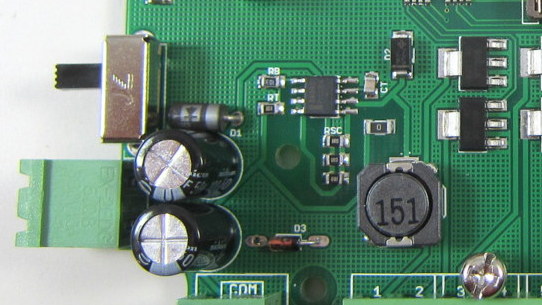
On OpenSprinkler Pi, Rsc is reduced to 0.33 ohm (three 1 ohm resistors in parallel) in order to provide higher current required by RPi. The picture on the left shows the switching regulator section on OpenSprinkler Pi, which uses all surface mount components.

MC34063 is quite flexible. It’s not only useful for step-down voltage conversion, but it can also do step-up conversion (i.e. the output voltage is higher than input voltage), and voltage inversion. On the other hand, it requires a number of peripheral components, and picking the right component values can be tricky, especially if the output current can vary across a wide range. It’s also prone to noise (remember those annoying humming noise from cheap power adapters), and its maximum current is limited to 1.5A.

Overall if you want a cheap switching regulator, and your circuit draws roughly a fixed amount of current well below 1.5A, then MC34063 is a great choice to consider.

LM2596
More recently I’ve started using LM2596 as a replacement for MC43063. I came across it when I was shopping for a modular step-down converter and noticed this one from Amazon.com. LM2596 provides up to 3A output current, requires only a small number of peripheral components, and is more reliable and less noisy. In fact, when I started working on OpenSprinkler, I have used a similar product LM2574 for a while, but that has a current limit ot 500mA, and the switching frequency is much lower.

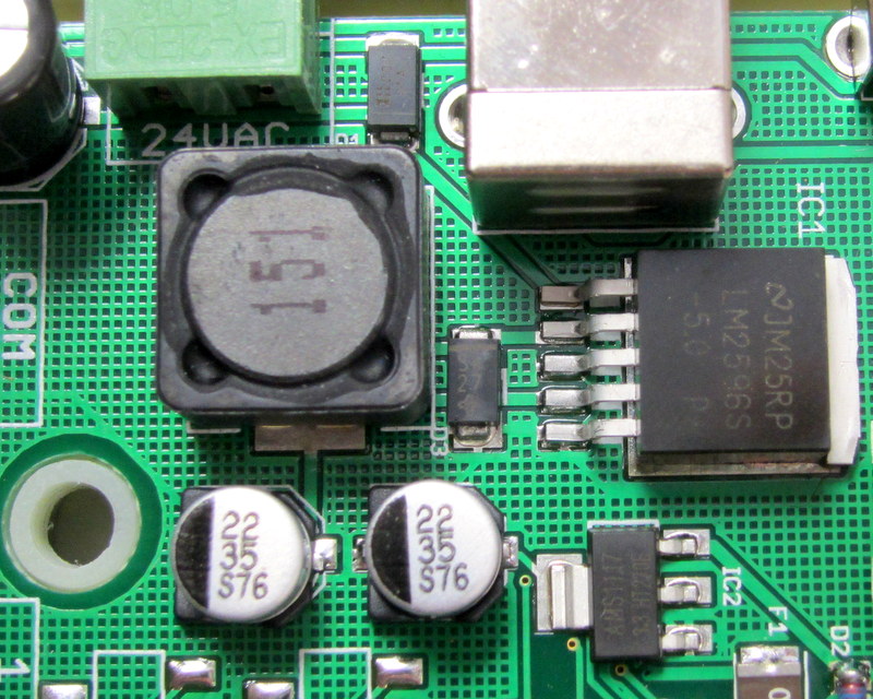
Here is the new design of the voltage conversion section in the upcoming OpenSprinkler 2.0 and OpenSprinkler Pi 1.1:

lm2596_schIMG_2709

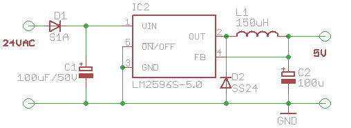
It uses LM2596-5.0, which has a fixed output voltage of 5.0V. The number of peripheral elements is minimal, and the circuit design is very clean. The main downside is that it is considerably more expensive than MC34063. So the extra capabilities don’t come for free 🙂 Still, for reliability and clean design, I have decided to adopt it for all future circuits.


4. Other Solutions

The above has summarized the common choices I’ve learned through my experience. There are certainly other solutions as well. For example, you can use a transformer to step 24VAC down to 5VAC, then from that point on you can use a rectifier followed by a linear regulator to convert it further to 5VDC. This is fairly efficient because transformers can have high efficiency, and the linear regulator in this case is also efficient because the voltage differential is small. However, transformers are bulky and expensive. and this solution is not suitable if the input voltage varies across a wide range.

Another choice is to use a capacitor for current limiting, in conjunction with a rectifier and a 5.6V Zener diode for voltage regulation. The idea is similar to solution 1 above, except it uses the capacitor’s reactance (instead of resistor’s resistance) to limit current. Since there is little energy loss, this is very efficient and is similar to the transformerless power supply design, which is frequently found in small wall adapters. Unfortunately, to provide sufficiently high output current (more than tens of milliamps), you will a capacitor that has high capacitance (e.g. 100uF) and is non-polarized. This is not easy to find in real life.

transformerless_sch

Finally, you may be wondering why not use a resistor-based voltage divider to split 5VDC out of the 33V rectified input? Well, this is a terrible idea in almost any circumstance I can think of. The reason is that the output voltage will fluctuate considerably depending on the current draw. In other words, it is not regulated. So I can’t think of any real use of it other than providing voltage reference.

That’s all. I hope this blog post provides useful information for your own power supply design.


Interface with Remote Power Sockets – Final Version

Update: check out the RFToy — an easy-to-use standalone gadget to control remote power sockets. Also, support for remote power sockets have been added to OpenSprinkler firmware 2.1.1.

In previous blog posts, I’ve described two ways to use an Arduino to interface with an off-the-shelf remote power sockets / switches. The first method uses transistors to simulate button presses. It involves some soldering and hacking the remote control unit. The second method uses an oscilloscope to sniff the signal sent by the remote control, and then simulates the same signal using an RF transmitter. But what if you don’t have an oscilloscope, or don’t know where to place the probe to take the measurement? In this post, I will describe a very simple method to sniff remote control signals. It only requires a 434 MHz RF receiver, a couple of resistors, an audio cable, a sound card (with line-in), and an free audio processing software. (Note: some RF remote sockets work at 315 MHz frequency range).

Update: check out the RFToy — an easy-to-use standalone gadget to control remote power sockets. Also, support for remote power sockets have been added to OpenSprinkler firmware 2.1.1.

To get started, I picked a set of indoor wireless power sockets from Amazon. This is different from the model I had before, and it’s not based on the PT2262 encoder, so I cannot predict the RF signal by just looking at the circuit board connections. The reason I picked this model is because it has separate On and Off buttons for each socket, instead of just a Toggle button. So if you want to make sure the socket is on, just repeatedly send the on signal. With only a toggle button, if there is a power reset or if the previous command was not successfully received, you will mess up the control and end up with completely flipped on/off status.


RF Sniffing Circuit

Ok, here is the fun part: how can we sniff the signals sent by the remote control to the sockets? It turns out that most of these remote controls work in the 434 MHz band (note: some work in 315 MHz), so we can use a cheap 434 MHz RF receiver to intercept the signal. To record the signal, a simple way is to use your sound card and an audio recording software. The sound card can digitally sample the signal at high speed (e.g. 48,000 Hz), and it can record a signal over a long time, so it is more convenient than using an oscilloscope.

This is by no means a new idea. I found it when reading this forum post. Scroll down and you will see the schematic to make the sniffing circuit. One important thing is that you should plug the audio cable to the Line-In jack on your sound card, not the Mic jack.

The picture on the left is my implementation of the circuit. I used my handy AASaver to provide the +5V needed by the RF receiver. This way, the whole circuit sits on a breadboard without any external power adapter. I can easily insert it to the sound card at the back of my desktop PC.


Record the Control Signals

I used the open-source Audacity software in Linux to record the signals. All I have to do is to start recording, and press each of the 6 buttons on the remote control. Then I will zoom in and analyze the signals. Below is a snapshot:

Basically when you press a button, the same sequence is sent multiple times. Each sequence consists of two types of square waves: a long on followed by a short off, which I call a ‘1’, and a short on followed by a long off, which I call a ‘0’.

How can we find out the timing (i.e. the width) of the signal? In Audacity, if you zoom in the signal to the extreme, you will see the actual signal sample points. Remember that we know the sampling rate, which is 48000 Hz by default. So if we count the number of sample points, and divide that by the sampling frequency, then we will get the timing. For example, below is a snapshot of a short on. I counted that there are about 21 sample points, so the width of it (i.e. a short on or short off) is

Similarly, I figured out that a long on or long off is about 1300 us, which is three times the width of a short on or off. Also, there is about 12.5 ms delay before re-sending the same sequence. These timings don’t have to be very accurate.

With the timings figured out, I can now write down the complete sequence corresponding to each button:


Socket 1 on: 1001 0000 0010 1000 00000000000
Socket 1 off: 0101 0000 0010 1000 00000000000
Socket 2 on: 1001 0000 0010 0100 00000000000
Socket 2 off: 0101 0000 0010 0100 00000000000
Socket 3 on: 1001 0000 0010 0010 00000000000
Socket 3 off: 0101 0000 0010 0010 00000000000

Each ‘1’ is a 433 us on followed by a 1300 us off, and each ‘0’ is a 1300 us on followed by a 433 us off. The first 4 bits indicate socket on/off, the next 8 bits are always the same, and the 4 bits following from that indicate the index of each socket.

With these patterns recorded, I can reproduce the signal using an Arduino and a 434 MHz RF transmitter. The RF transmitter has one data pin, which can be connected to any Arduino I/O pin. Since there is a little bit of overhead when using Arduino’s delayMicroseconds function, I reduced the short delay time to 410 us. This way, the signal generated by the code is almost identical to the that produced by the remote control.

Download
  • Download example Arduino code here. This example program assumes the RF transmitter data pin is connected to Arduino pin D3, which you can change at the beginning of the file.


Use OpenSprinkler to Control Power Sockets

Now that my Arduino can talk to the remote power sockets, how about adding Internet-based control? For example, sending control signals through a web interface, or even setting a time schedule to turn on or turn off sockets automatically during a day? Aha, my OpenSprinkler is perfect for this purpose. There are two reasons, first, the OpenSprinkler is an integrated circuit that includes ATmega328 + Ethernet + LCD + USB programmer; second, the latest OpenSprinkler software provides a nice web interface where you can set an interval schedule or switch to manual control mode. All that I have to do is to connect the RF transmitter using one of the available pins on board, and then add a few lines of code to send the RF signal wherever the corresponding sprinkler station is turned on or off. This way, I can easily use the same web interface to control power sockets. Internet of things instantly!

The image above shows my implementation. I used a half-built OpenSprinkler, with everything except the switching regulator section and the solenoid driver section. The RF transmitter is connected to the controller using three wires. Again, one of the nice things is that I can directly use the software already written for OpenSprinkler, to set a time schedule for automatically turning on or off power sockets. In addition, I can switch to manual control mode, which also has built-in timers.

What’s Next?

My next plan is to use the sniffing circuit to reverse engineer RF signals sent from wireless temperature, humidity, and rain sensors. This will allow me to use an Arduino and a RF receiver to decode the wireless data and get local temperature, humidity, and rain information. Of course the tricky part is to figure out how the data is encoded. So I will have a couple of posts in the next week or so about RF hacking. Stay tuned!

A New Way to Interface with Remote Power Switches

Update: check out the RFToy — an easy-to-use standalone gadget to control remote power sockets. Also, support for remote power sockets have been added to OpenSprinkler firmware 2.1.1.

Note: the RF transmitter used in this article is available for purchase in the shop page.

In a previous post I described a way to use an Arduino to interface with remote controlled power sockets. The idea was to make use of the original remote control, and a high-side transistor switch to simulate button presses. This approach is generic: you don’t need to know how the remote control signal is encoded, instead, just treat the remote control as a black box and simulate the button presses. However, the downside of this approach is that it requires soldering wires and components to the remote control, which is quite a bit of work.

Update: check out the RFToy — an easy-to-use standalone gadget to control remote power sockets. Also, support for remote power sockets have been added to OpenSprinkler firmware 2.1.1.

Recently, inspired by the JeeLabs KAKU remote switch article, I figured out a new way to interface with these remote power switches. The method published by JeeLabs uses an RFM12B transceiver, which is cool because my OpenSprinkler design has a reserved spot for RFM12B. Unfortunately after many experiments I was unable to get it to work with my switches. However, I did succeed by using a 433MHz RF transmitter purchased from SparkFun. So below I document the process of how I did it.

To begin, I took apart the remote control. The goal is to reverse engineering the signal sent from the remote control, so that I can use an Arduino to simulate the same signal. This will allow me to use a program to control the power sockets. The schematic of the remote control circuit can be found in the previous post. Basically it consists of an encoder IC (HT2262 or PT2262) and a 433MHz RF transmitter circuit.

By connecting an oscilloscope to the circuit I was able to analyze the signal patterns. Details can be found in the video attached at the end of this post. Below are the patterns I observed when button 1 is pressed (corresponding to power socket 1).

The signal consists of two basic patterns: a short HIGH followed by a long LOW, which I call a ‘0’ all together, and a long HIGH followed by a short LOW, which I call ‘1’. The long part is roughly 500us and the short part is roughly 160us (so it’s about a 3:1 ratio). Each signal sequence consists of 25 bits: the first 16 bits are always ‘0000 1111 0101 0101’, which I call the ‘signature’; and the next 8 bits are the ‘command’, which correspond to the index of the power socket; finally, there is always an ending ‘0’.

For example, the entire sequence to toggle socket 1 is

0000 1111 0101 0101 1100 0001 0

the entire sequence for socket 2 is:

0000 1111 0101 0101 0011 0001 0

and for socket 3 it is:

0000 1111 0101 0101 0000 1101 0

Again, a ‘1’ means a 500us HIGH followed by a 160us LOW, and a ‘0’ means a 160us HIGH followed by a 500us LOW. When a button is pressed, the sequence is repeated several times, for robustness I guess.

Interestingly, you can OR the command part in order to toggle two or three sockets at the same time. For example, the sequence below will simultaneously toggle socket 1 and 2:

0000 1111 0101 0101 1111 0001 0

Next, to simulate the remote control signal using an Arduino, I used a 434MHz RF transmitter from SparkFun. This transmitter has only 4 pins: Gnd, Vcc, Antenna, and Data. The data pin can be connected to any digital pin on the Arduino in order to send the control sequence as analyzed above.

For demonstration, I used Arduino pin 10 to send the control sequence through the Data pin. The connection is as follows: VCC->+5V, GND->GND, DATA->Digital 10, ANT->a short wire. The supply voltage for the RF transmitter can be anywhere between 1.5V to 12V. The higher the voltage, the longer the transmission range. Normally 5V should be good for at least 15-20 meters. If you want the highest range, use a +12V power adapter to power your Arduino, and connect the RF transmitter Vcc pin to the Arduino VIN pin. Alternatively, you can add a voltage boost converter to bump +5V to +12V.

Below you can download the Arduino program I wrote. The code should be easy to follow.

If you have a different remote controlled power switch, you can follow the same procedure to find out the control sequence, then modify the program accordingly. A video demo is provided below:

Credits: the method is based on JeeLabs KAKU remote switch and the code is based on the kaku_demo sketch included in their RF12 Arduino library.

Note: the RF transmitter (434MHz) is available for purchase in the shop page.


Update 1: apparently if you look at the datasheet of PT2262, which I found a copy here, it explains how the encoding pattern is computed. The ‘signature’ part has to do with the status of each pin from A0 to A7 on PT2262 – whether the pin is connected to GND, VCC, or floating, and the ‘command’ part is determined by the status of each pin from D0 to D3. I compared the circuit with the datasheet and verified that the pattern I observed from the oscilloscope matches the calculation. Also, according to the datasheet and the resistor value I found on the remote control, it looks like the long delay should be about 400us and short delay 133us, which is a bit different from the 500us and 160us observed from the oscilloscope. Also, the ending ‘0’ in my sequence turns out to be a ‘sync’ bit, which is 133us high followed by 4200us low. The fact that my original sketch has worked means there is a some level of tolerance in the timings. So they do not have to be highly accurate.

Update 2: new version of remote control. A reader of this post, Chuck, sent me a question that the sketch doesn’t seem to work with his remote control. After researching this issue, we found that the new version of the remote has changed to use SMT components and also has changed the coding pattern. Chuck sent me an image of the back of the PCB. From the image and the datasheet of PT2262, I figured out the new coding pattern. Basically, the ‘signature’ part of the code has been changed from

0000 1111 0101 0101

to

1101 0111 0101 0101

More technically, the coding pattern can be derived from the connections of Pins 0-7 of PT2262. In the newer version (from the PCB image on the left), the first 4 pins are connected as HIGH, FLOAT, FLOAT, HIGH, whereas the older version is connected as LOW, LOW, HIGH, HIGH. Here HIGH means connected to Vcc, LOW means connected to Ground, FLOAT means unconnected. Taking a look at the datasheet, you can easily figure out the actual code: LOW -> 00, HIGH -> 11, FLOAT: 01.

Chuck sent me his modified code, which you can download here.


Use Arduino to Interface with a Remote Controlled Power Switch

Update: check out the RFToy — an easy-to-use standalone gadget to control remote power sockets. Also, support for remote power sockets have been added to OpenSprinkler firmware 2.1.1.

For a while I’ve been looking for a way to switch household power line (110V) devices. One of the simplest options is to use a relay that is connected to the power line. This is easy in concept but quite dangerous to work with. You don’t want to accidentally touch the power line wire and shock yourself. A much better option is to use the powerswitch tail, which insulates the relay and the relevant circuity inside a plastic enclosure, leaving only two MCU pins to interface with. Much safer. But you still have to run wires between your MCU and the power socket. I am more interested in an wireless option.

Recently I purchase a set of remote controlled switch sockets from Amazon. It comes with one remote and three sockets, each of which can be individually switched. The whole package is quite cheap. The way this works is that you plug the sockets into the wall, and when you press a button on the remote, the corresponding socket will switch, thus turning on or off the device connected to the socket.

I took apart the remote control and found that the circuit is quite simple. It’s based on an HT2262 remote control encoder and a 434 MHz transmitter circuit. In fact, the schematic of the circuit is well documented in the datasheet of the encoder:

From the schematic, it’s quite clear that when a button is pressed, the input voltage is fed to one of the encoder pins (as well as the VCC pin of the encoder). Then the encoder will send the signal to the RF transmitter circuit. The RF signal will be received at the power socket side and decoded. Very simple. Now, to use my Arduino to interface with this power switch, all I need to do is to simulate a button press by sourcing a positive voltage to wires labeled SW1, SW2, SW3 etc. It turns out that the HT2262 can work with a fairly wide range of voltage: from 4V to 18V. Clearly the 5V output from an Arduino IO pin falls within the acceptable range. So I can simply connect those wires individually with Arduino I/O pins, and write a program that outputs HIGH momentarily when I need to switch a device. The only downside is at 5V the transmitting range is limited. The higher the input voltage, the longer distance it can transmit. So a more flexible design is to have a ‘source’ driver to supply higher than 5V to the encoder.

Update: check out the RFToy — an easy-to-use standalone gadget to control remote power sockets. Also, support for remote power sockets have been added to OpenSprinkler firmware 2.1.1.

This can be done by using a transistor based high-side switch. Here is a schematic:

Basically, when the IO pin outputs low, transistor Q1 (NPN) turns off, and its collector is in high impedance status. Hence Q2 (PNP) is also off. Now, when the IO pin outputs high, Q1 conducts, driving the gate of Q2 low. Therefore Q2 also conducts, sourcing +12V voltage to the encoder. The reason to use such a high-side driver is to be able to switch a high voltage (>=12V) using a relatively low-voltage (<=5V) control signal from the MCU.

I implemented this method on a small proto-board. Since the remote control has 3 buttons, I made 3 copies of the above high-side driver, and the entire circuit fits nicely inside the remote control cover. I soldered five wires out: +12V, GND, and three control wires. A picture is shown on the left.

With this modification, I can now switch power line devices such as home lights and heaters using a microcontroller. Better, I can connect the remote control with my OpenSprinkler Controller, thus I am able to control power line devices through a web interface. The video below show a demo. Enjoy!