First Try on Panelized PCBs

As I am getting more experienced with the TM-240A pick and place machine (in the following I will call it the PNP machine, as in PNP transistors 🙂 ), I’ve been thinking of ways to improve productivity. One obvious way is to panelize PCBs, meaning to assemble multiple copies of the PCB onto the same board. This can help greatly reduce the overhead time of stenciling and PNP loading time. I have to admit, I’ve never done PCB panelization before. I did search online and found various tutorials, but it’s unclear to me how to exactly indicate the ‘V-cut’ layer to the PCB manufacturer.

But I found an easier route. Recently I’ve been ordering PCBs directly from a Chinese company called 深圳嘉立创 (http://www.sz-jlc.com). I got to know this company very randomly, actually through watching the beginning clip of the SparkCore Kickstarter video. The company has a very streamlined PCB manufacturing process, where you can track each step of the PCB making, all the way from drilling, to printing layers, to etching, to optical inspection, to solder-mask and silkscreen printing, to testing, and to shipping. It’s completely amazing (except the website only has Chinese version…). Anyways, when you order PCBs from their website, apparently you can specify how you’d like to panelize your PCBs. You don’t need to panelize the PCB yourself in Eagle (which I haven’t learned how to do yet), but you just need to describe your panel design (like 2×3, 4×4 etc.), and they will do the panelization free of charge. Isn’t that awesome?

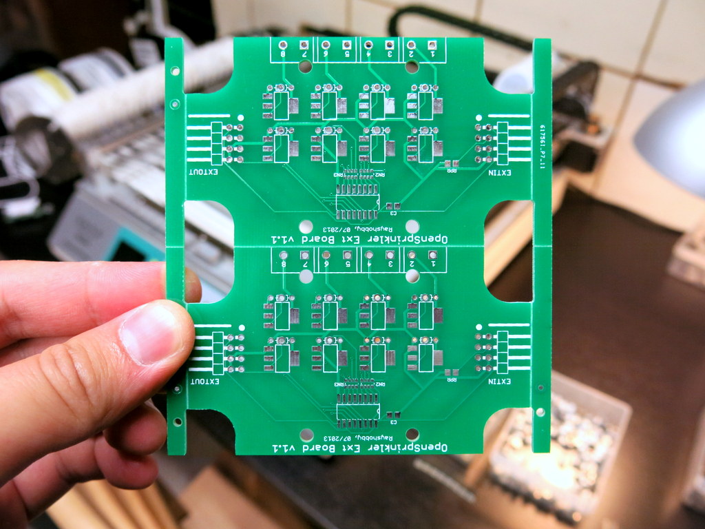
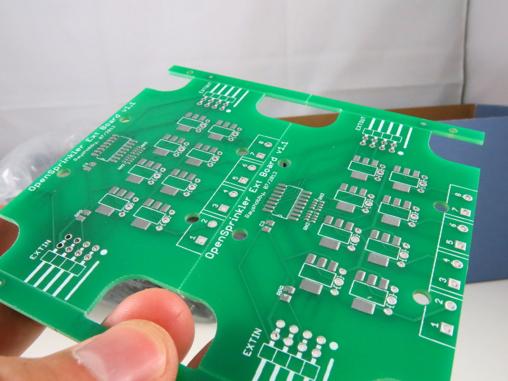
Since this is the first time I’m ordering panelized PCBs, I wanted to be careful. So I ordered a very simple board — the OpenSprinkler Zone Expansion board, with the simplest panelization — 1×2. And the image on the left below shows what I received. Very neat. I also asked them to add an extra 10mm border on each side, and fiducial points (these I paid extra for). Since the board is not rectangular shaped, the panel comes with routed edges on the curved sections, and V-cuts on the straight lines. This way, it can be easily de-panelized by simply snapping each board off along the straight edges. Pretty awesome, especially considering I didn’t have to do anything in Eagle to create the panel design 🙂

IMG_0066IMG_0065

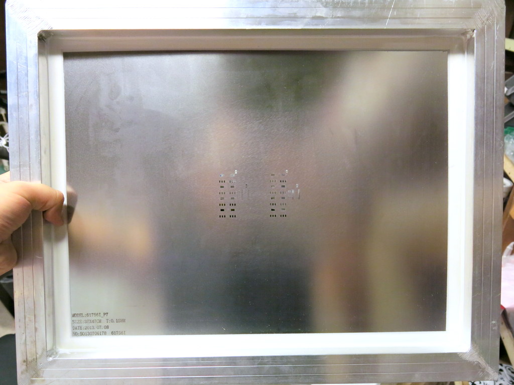
So what’s the picture on the right above? This is also something new to me: apparently when you order PCBs from the company, you can also order a laser-cut solder paste stencil to go with your PCB order. It’s only 10 extra bucks, almost a no-brainer. I ordered one for this particular batch, so I can experiment with it. The stencil is made from a steel sheet, and mounted on a metal frame. It’s quite large (37cm x 47cm), so you will need a stencil printing machine that can handle a board of this size. Fortunately I got a fairly big manual stencil printing machine a while back, so I can put it to good use now.

IMG_0067IMG_0069

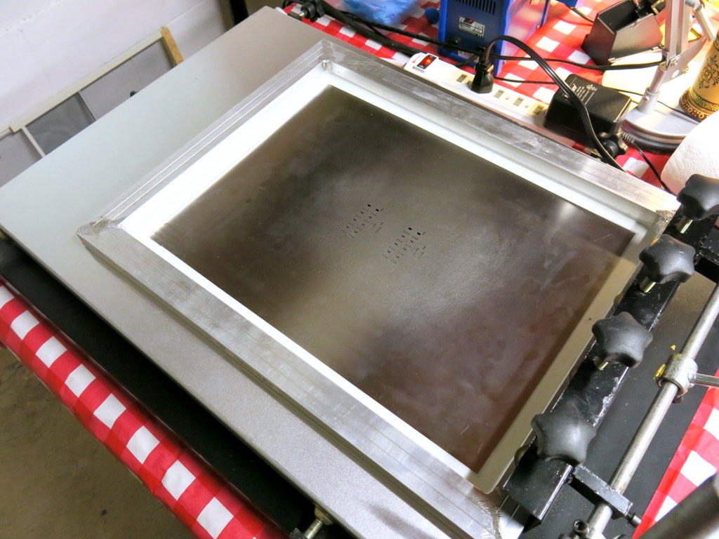
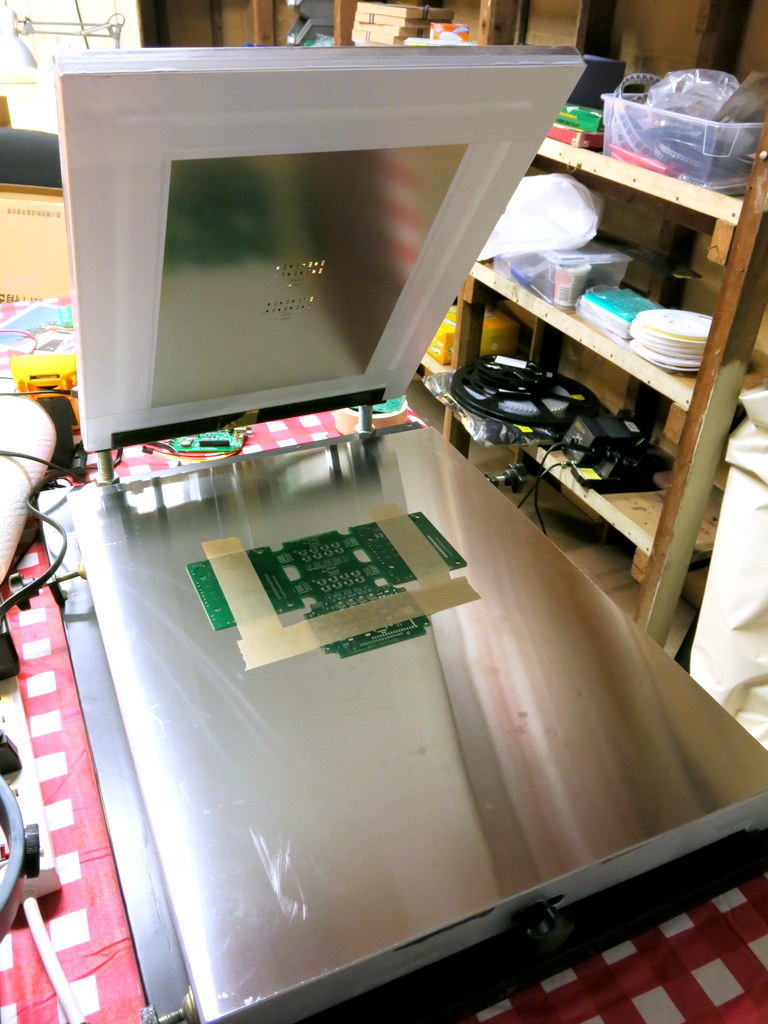
In order to use the stencil, the first thing I did was to mount the stencil frame onto the printing machine. Once mounted, you can easily lift the stencil up and down, to quickly insert and take out stenciled PCBs. Then I aligned the PCB to the stencil holes. This is very tedious — since the stencil is made of steel, which is opaque, there is no easy way to align them. I had to do a lot of trial and error and eventually was able to get them perfectly aligned. Once aligned, temporarily fix the PCB in place by using some tape. Finally, use three old PCBs to make a frame around the center PCB. Then you are all set.

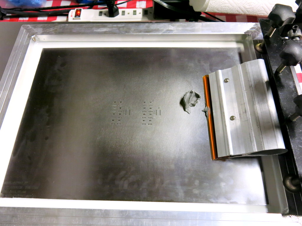
With the stencil printing machine (albeit manual), applying solder paste works like a charm, and is much faster than using my home-made stencils. The stenciling quality is also excellent (see the picture on the right below). Apparently they optimized the stencil design, and created small ‘crosses’ around relatively big (0805 or above) components. This prevents the solder paste from smearing underneath the stencil. Very smart!

IMG_0072IMG_0079

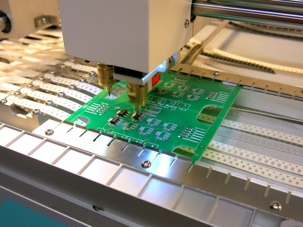
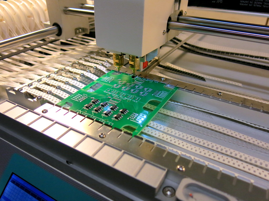
Next step is to populate components. The TM-240A pick and place machine supports PCB panelization. All that I had to do was to open the existing PCB configuration file, and add a new line for each additional sub-board, indicating the amount of shifting from the first sub-board. With this simple change, the PNP machine can now populate twice as many components, a real time-saver!

IMG_0074IMG_0076

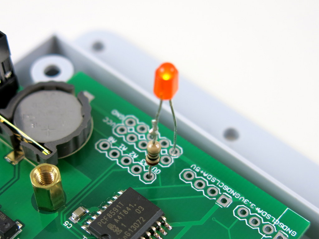
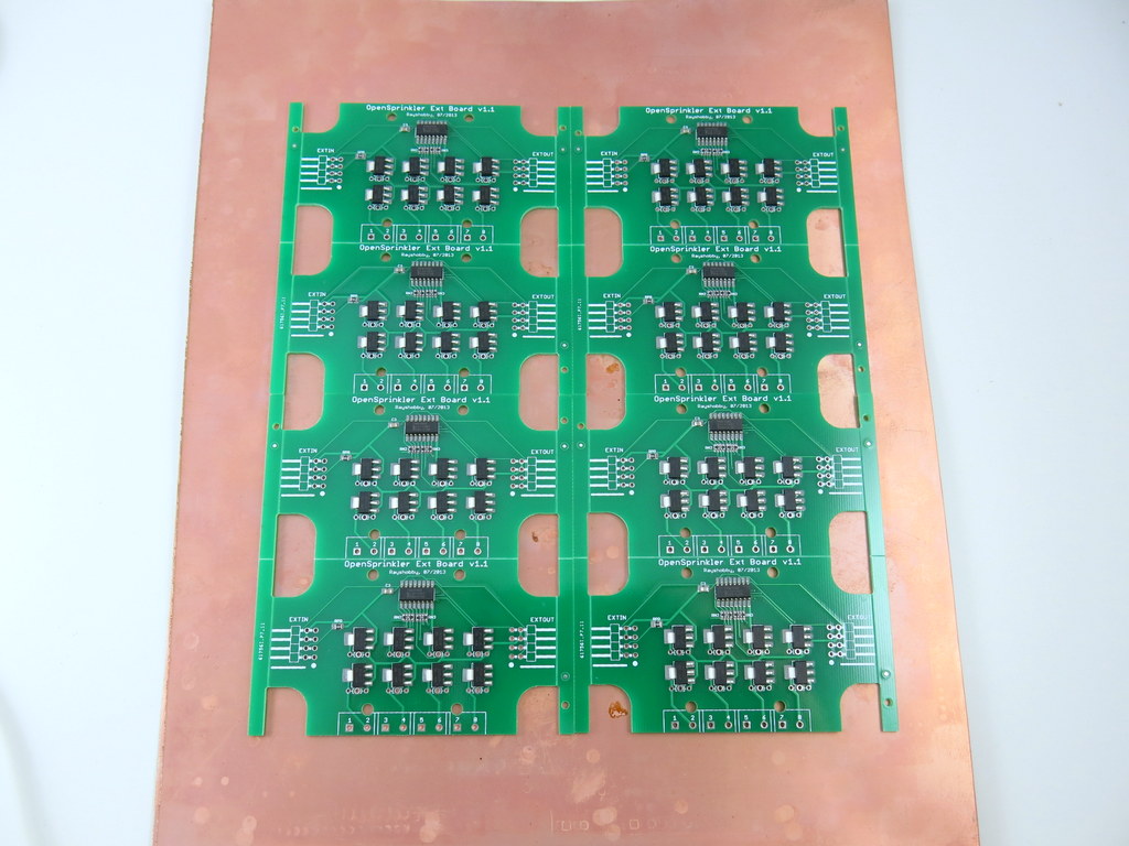
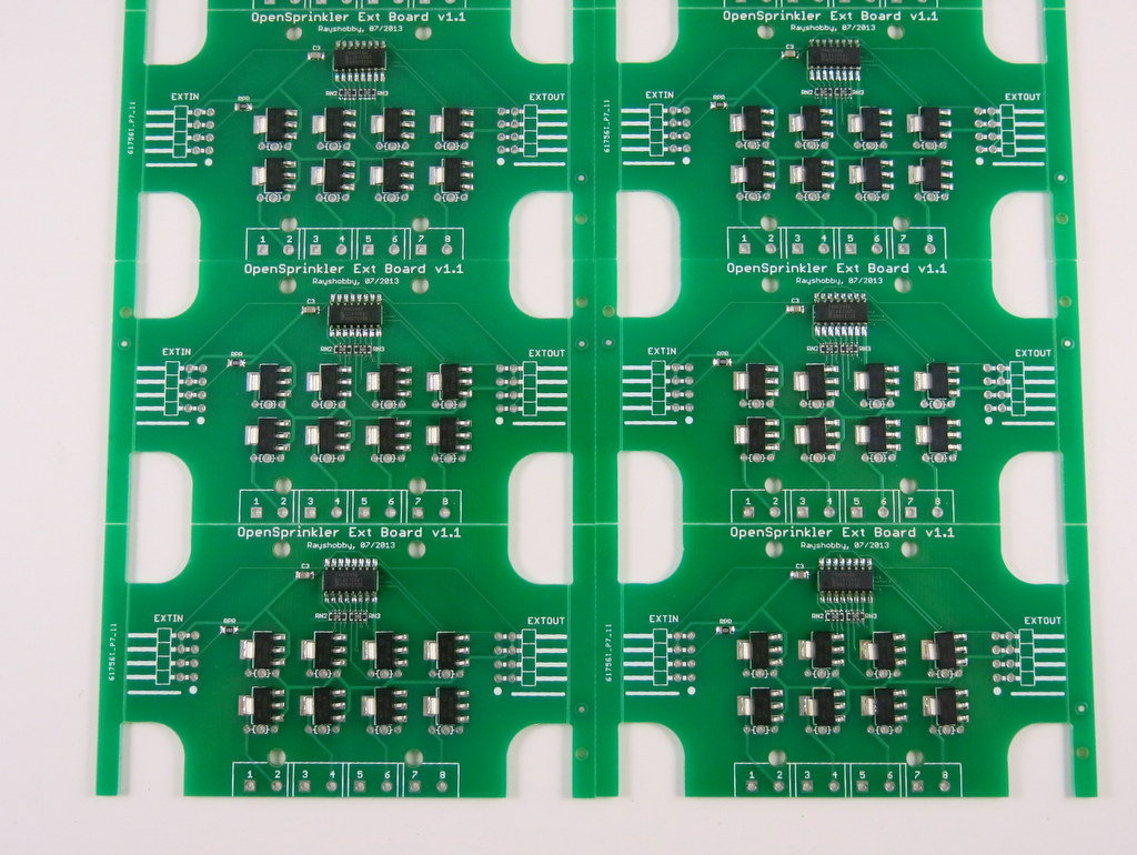
Here are pictures of four boards before and after reflowing. The reflowing quality is pretty good.

IMG_0077IMG_0081

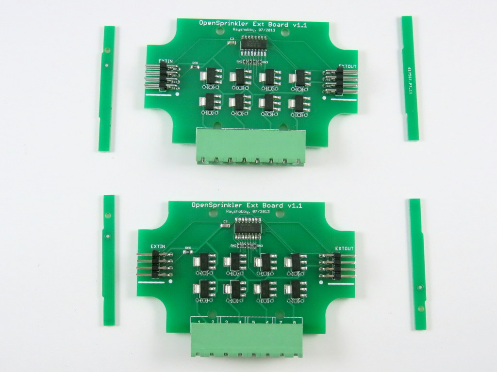
Finally, to separate the boards into individual pieces, as I said, just snap the boards along the V-cuts. Use some strength along the cuts, and they should come off pretty easily. Here are the final results (with the through-hole pin headers and screw terminals soldered in place). Neat, isn’t it 🙂

IMG_0082

So, to summarize, it takes very minimal effort to make panelized PCBs. First, when ordering PCBs, tell the manufacturer how you would like to panelize the board. They will do the work for you. Next, order a professionally made solder paste stencil with the PCB order. Finally, modify the pick and place configuration file to reflect the number of sub-boards and the shift amount of each. That’s it. Not bad at all!

OpenSprinkler Mobile Web App Instructions (with Video)


Update: OpenSprinkler new mobile app (native version) is now available on all platforms. Search ‘opensprinkler’ in iOS App Store, Android Play Store, or Windows Phone Store, then download and install the app. Additional details can be found in this blog post.


In this blog post, I will walk you through the basic steps to set up and use the OpenSprinkler mobile web app developed by Samer Albahra. I’d like to thank Samer for making this app available, and credits should be attributed to him. Initially I was planning to write a long post with textual instructions. But then I felt this app is such a significant contribution that it deserves its own video tutorial. So please take a look at the video below first. As the video is already quite long, I will keep the textual information short, with only a summary of the necessary steps, download links, and pointers to resources. Since the app is a work in progress, feel free to leave your comments and suggestions at the Rayshobby Forum.


Prerequisites

In order to use this app, you will need a working OpenSprinkler setup, such as

  • OpenSprinkler 1.x running firmware version 1.8.2 or above (note: firmware 1.8.3 preferred);
  • or OpenSprinkler 2.0 running firmware version 2.0.0 or above;
  • or OpenSprinkler Pi any version running Dan’s interval_program (equivalent to firmware 1.8.2).

If you have OpenSprinkler 1.x with firmware earlier than 1.8.2, please follow the Firmware Update Instructions to re-flash the microcontroller with the latest firmware.

Also, if you are not familiar with the concept of a mobile web app, please take a look at my previous post about the app. Simply speaking, it’s an app that runs in a browser. It’s somewhat slower than a native app, but the biggest advantage is that it’s cross-platform (i.e. same app runs on both iOS, Android, etc., even desktop browsers). By adding the web link to home screen, the app will appear like a true native app.

NOTE to keep in mind: the app provides an alternative front end to the OpenSprinkler controller. The default front end, which is the controller’s webpage (accessed by typing in the controller’s ip in a browser), is still available and functioning. Any operation you apply through the app will also be reflected in the default front end.


Version 1: Hosted App on Rayshobby.net

Samer made the app available in two versions. The first is a hosted app available at the following url:

http://rayshobby.net/apps/sprinklers/

Type this in the browser on your smartphone, tablets, or even desktop computer, and you can start using it immediately. However, before you proceed, make sure you have port forwarding set up on your router. See below.

Port Forwarding: because the hosted app needs to communicate with your OpenSprinkler through HTTP commands, your controller must be accessible by the rayshobby server. To do so, you need to set up port forwarding on your router, so that an external HTTP request to your router will be mapped to your OpenSprinkler controller. This requires knowing your OpenSprinkler’s IP address and port number (default is 80). Please refer to your router’s user manual for instructions. In addition, you can use dynamic DNS service (such as dyn.com, freeDNS etc.) to set up a DNS name for your router (i.e. an easy-to-remember name such as rayshobby.dyndns-web.com instead of the router’s IP). Most routers support dynamic DNS service as well.

Logging in: going back to the app, on the log-in page, type in your router’s IP (or dynamic DNS), optionally followed by the port number (if it’s not the default 80), and your OpenSprinkler’s access password (the default password is ‘opendoor’). Then click on the button.

Add Link to Homescreen: most mobile browsers support adding (or bookmarking) a link to homescreen. This creates a homescreen icon, which you can simply click to start the app each time.

Features: the app has implemented all features available on the latest OpenSprinkler firmware. It provides a more stylish and intuitive interface than the default front end. For example, you can use slidebars to set values, there is a status bar that shows the currently running station with count-down timer, the app’s program preview provides an easy way to switch to a different day, everything is optimized for mobile viewing experience, and finally since the app is a front end itself it does not require external Javascript as required by the default front end. Please follow the video tutorial above and try out the app yourself. Most of the features are self-explanatory.

Donation: Samer wrote the app and shared it for free. I can’t thank him enough for making this app available and so polished. If you like the app, please consider donating some money to support his work. The donation link is available on the app’s ‘About’ page (accessible by clicking the control panel button at the upper-left corner of the app).

Summary: to summarize, in order to use the hosted web app, all you need is to set up port forwarding on your router, and use the hosted web app’s url above. That’s it!


Version 2: Self-Installed App on A Local Web Server

The second version is a self-installed app that requires using a local web serer. Most of the features in the second version are shared with the hosted web app above, however, by using a local web server you gain two additional features that may be very useful: logging, and weather-based rain delay.

Installation: for installation, simply follow the instructions on my previous post about the web app, particularly the How to Set it Up (using Raspberry Pi as example) section.

Logging Feature: the self-installed app records stations runs and keeps the history of station runs in a log file. On the app’s homepage you will see a button. Clicking on it brings out the log view, which categorizes log data by station names.

Weather-based Rain Delay: having a local web server also allows weather-based rain delay. This feature is developed by Andrew Shilliday (thank you, Andrew!). Basically, it’s a script that periodically pulls data from Yahoo Weather API (using your location information), and enforces rain delay if certain weather conditions are met. Technically, the data from Yahoo Weather contains a condition code that tells the local weather condition (e.g. showers, thunderstorm etc.). The script is associated with a data file that defines the amount of rain delay hours when a certain condition code is detected. For installation and setup instructions, please refer to Andrew’s GitHub page:

https://github.com/andrewshilliday/OpenSprinkler-WebRainDelay

This is a work in progress, and we are planning to integrate this feature into the OpenSprinkler firmware so that in the future it will not need installation any more.


Resources and Links

I am really glad to see these wonderful user contributions. They tremendously help make OpenSprinkler a better product, and I learned a lot through the forum discussions, which in turn inspired new ideas. Below I list the currently active forum threads that are related to the mobile web app development and the weather feature:

We are actively working on making the weather-based control a firmware feature. If you have ideas and suggestions, please feel free to leave them at the forum. Thanks!


Announcing OpenSprinkler Pi v1.2

Hi, this is a new product post for OpenSprinkler Pi (OSPi) v1.2. Since its original release, OSPi has become a very popular product. This version is a minor revision. The main change compared to version 1.1 is the addition of a PCF8591T 8-bit A/D D/A converter, which provides four independent 8-bit analog input pins, and one 8-bit analog output pin. The reason this has been added is that Raspberry Pi (RPi)’s GPIO pins do not have built-in ADC capability. In order to interface with analog sensors (such as soil moisture sensor, light sensor etc.), you would need an ADC unit. The addition of the PCF8591T chip allows OSPi to provide on-board analog inputs as well as output. This makes it more convenient for your prototyping need. Other than this, the rest of the circuit is pretty much the same as before, with 24V AC to 5V DC switching regulator (based on LM2596S), DS1307 RTC and backup battery, 74HC595 shift register and triacs. Here are two pictures of the OSPi v1.2 board:

IMG_0004IMG_0008

If you Google ‘RPi ADC’ you will find plenty of choices of ADC modules and tutorials on how to get them to work with RPi. Why did I pick PCF8591T? There are several reasons. First, it’s low-cost: volume pricing is just a couple of dollars per piece. Second, it provides four independent A/D channels, and one D/A channel. This means you can use one chip to interface with 4 different analog sensors, and additionally you can get one channel of analog output. According to the datasheet, the analog output is implemented with resistor divider chain, which is sometimes a better choice than PWM. Also, it uses I2C interface, so it doesn’t require any extra GPIO pins from RPi. Overall it’s a very attractive choice. The main downside is that it’s only 8-bit. This means the analog input value is on a resolution of 0 to 255, same with analog output. A lot of the other chips provide at least 10 bits of precision. But I figured that 8-bit is sufficient in many cases, so I settled with this choice.

The chip, together with analog pinouts, are located on the right-hand side of the board:
IMG_0006_annotated

For convenience, I’ve also provided a separate pair of VCC and GND pinouts for each analog channel. The picture on the left below is an example of plugging in a MCP9700 temperature sensor directly to the pinouts; and the picture on the right below shows an LED (with current limiting resistor) plugged into the analog output channel, to allow programmable control of the LED brightness.

IMG_0005IMG_0009

Suppose this gets you interested, the next question is how to program RPi to talk to the ADC chip? Fortunately there are plenty of tutorials online. In particular, I found the following posts very useful:

If you are confused and just want a quick demo. Here is a short tutorial to get you started.

First, run sudo i2cdetect 1 to check if the PCF8591T chip is detected. (Note, if you own RPi rev. 1 you should run sudo i2cdetect 0 instead). You should then see a printout like the following. This shows it has detected two I2C devices, one is at address 0x68 (that’s the DS1307 RTC), and one 0x48 (this is PCF8591T).
pcf8591t_i2cdetect

Next, you can use the i2cget command to read analog values from a particular channel. For example, run
sudo i2cget -y 1 0x48
repeatedly to sample the analog value from channel 0 (pin A0). To change to channel 1 instead, run
sudo i2cset -y 1 0x48 0x01
and then if you run sudo i2cget -y 1 0x48 that will return sampled value of channel 1, and so on.

To enable analog output, use the i2cset command. For example:
sudo i2cset -y 1 0x48 0x40 0xff
where 0xff is the 8-bit analog output value. You can change it to any value between 0x00 to 0xff to enable 256 grades of values. Since the chip is powered by 3.3V supply, that will translate to an analog output from 0V to 3.3V linearly.

The above use shell commands as an example to interface with the chip. There are also WiringPi and Python code examples which can do the same. When I get time I will write a more complete tutorial. For now, try to explore on your own 🙂

OpenSprinkler Pi v1.2 is immediately available for purchase at Rayshobby Shop, at the same old price.

NeoDen TM-240A Automatic Pick and Place Machine Demo — Part 2

Updates

  • Click here to see NeoDen 4 Pick and Place Machine with Vision System.

This is Part 2 of the NeoDen TM-240A pick and place machine demo. Today I placed the machine on a proper table downstairs in the basement, and had my first-hand results of a production run — namely using the pick and place machine to assemble the OpenSprinkler Pi circuit board. The results are pretty satisfactory. Here is a video demo:

Now I will explain the boring details 🙂 The first step is to load the component tapes. The user manual has no instructions on how to load the tapes, so you have to carefully watch the videos provided by the manufacturer to learn. OpenSprinkler Pi is relatively simple so it doesn’t require many components. The TM-240A can fit twenty-one 8mm tapes, four 12mm tapes, and two 16mm tapes. While this is almost twice as much as its sister model TM-220A, the 12mm and 16mm slots turn out to be quite precious — those can easily run out and you will have to place the remaining components by hand. In my case, I also have a few relatively bulky components (e.g. LM2596S in TO263 package, and surface mount inductors and battery holders) that I have to place manually. So these components will all be hand placed after the machine pass.

On TM-240A, there is a front component loader that can fit 10 ad-hoc components. These can be bulky components that are not handled by the standard feeders. This is a very nice feature, however, the downside is that for each slot only allows one component, so you will have to re-load for each circuit board.

Next, I made a configuration file for the PCB. I started by using the Eagle script file downloaded from this link. I appreciate the author for sharing the script, as it saved me a lot of time of trying to figure things out myself. The configuration file is a human-readable text file and is very easy to edit. For example, for any components that I want to place manually, I simply put a value of ‘1’ in its ‘Skip’ column. Also, you can manually refine the x-y placement of each component based on the outcome of a trial run. You will probably have to sacrifice some components while tweaking the configuration file. To avoid wasting solder paste, I used the double sided tape that came with the machine, which allowed me to do trial runs as many times as I want. Once the configuration file is finalized, you can then switch to stencil printed PCBs.

Next, I applied solder paste to the PCB using my home-made solder paste stencil. I then placed the circuit board on the PCB holder of the machine. Make sure you push the PCB all the way to the left. Because my PCB is not perfectly rectangular, the machine’s origin is not aligned with the PCB’s origin. To fix it, I simply write down the amount of origin shift in the configuration file. The shift amount can be either calculated from the board design file, or can be measured empirically.

The exciting moment starts after clicking on the machine’s ‘Start’ button. It’s quite pleasing to see the machine moving quickly and precisely, picking up components and dropping them down on the circuit board. The machine can automatically detect if a component has been picked successfully (based on its internal pressure sensor reading), and make up to three attempts if it fails. The machine is also equipped with two needle heads. I installed a smaller needle, suitable for 0603 and 0805 components, as well as a bigger needle, suitable for components on the 12mm and 16mm tapes. The dual-head design is very convenient, as I basically never have to change the needles any more.

With less than 20 components to place, the machine finishes each pass very quickly. From the video you can see that a few components are not aligned perfectly, but these present no problems at all for the reflow process. Indeed after reflowing, most components will get aligned well with the solider pads. Well, to be fair, I’ve used mostly large components (e.g. 0805), and have yet to try smaller components. So I can’t say if the accuracy is sufficient for boards mostly populated with 0402 components. But I am pretty sure 0603 should be all right.

Anyways, I hope the video has given you some ideas of the capabilities and limitations of this machine. The next steps I would like to try include adjusting the speed of the machine to see if that helps with the placement accuracy, paneling the PCB to improve productivity, and also try to use the front loader for some of the bulky components. Feel free to leave your questions and comments below. Thanks!