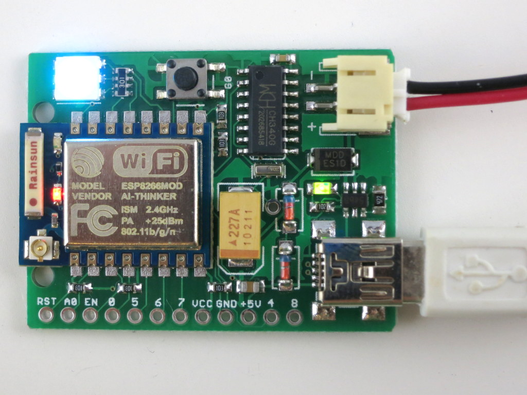
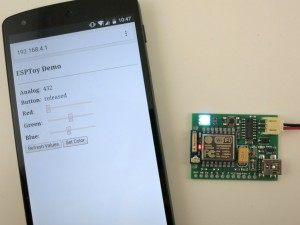
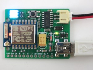
Since the first version of ESPToy, I’ve done some pretty rapid revisions. This post is to introduce the new minor revision 1.21, with LiPo battery jack and charger. As you can see in the annotated diagram below, the main components are the same as ESPToy 1.2: a color (RGB) LED, pushbutton (wired to GPIO0, so it can be used to bootload but also function as a general-purpose pushbutton), a surface mount ESP8266 module, CH340G USB-serial chip, mini-USB port, and breadboard pins. The ESP8266 module is pre-flashed with the latest Lua firmware, and a start-up demo (WiFi-controlled color LED). You can use the pushbutton to re-flash the firmware if necessary. The newly added components are the LiPo battery jack, charging chip (TP4054), and indicator LED.
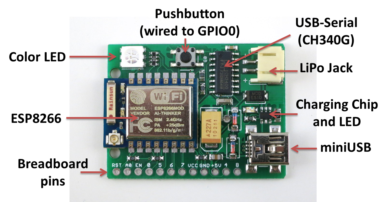
The LiPo jack and charger are due to popular requests. Since many users want to power the ESPToy with a LiPo battery, and make a standalone gadget, it makes perfect sense to add a LiPo jack. It also make sense to throw in a LiPo charging chip (the same as used on SquareWear and AASaver), to automatically charge the battery whenever a USB cable is plugged in. There is a green indicator LED which will turn off when charging is completed. The charging current is approximately 200mA.
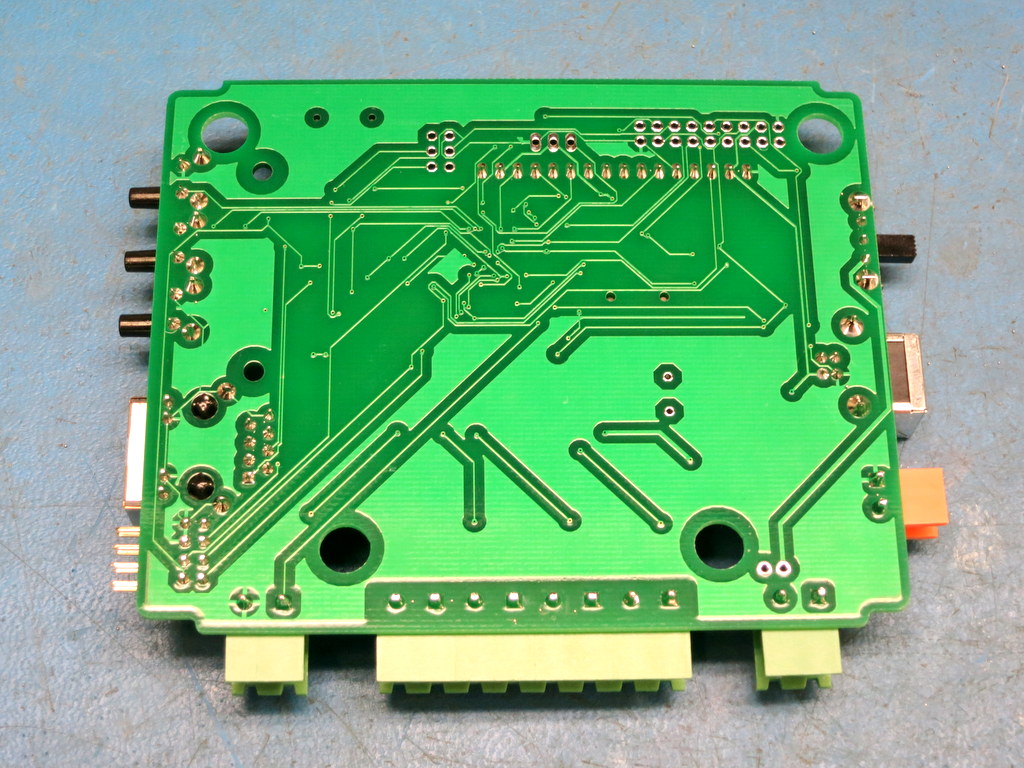
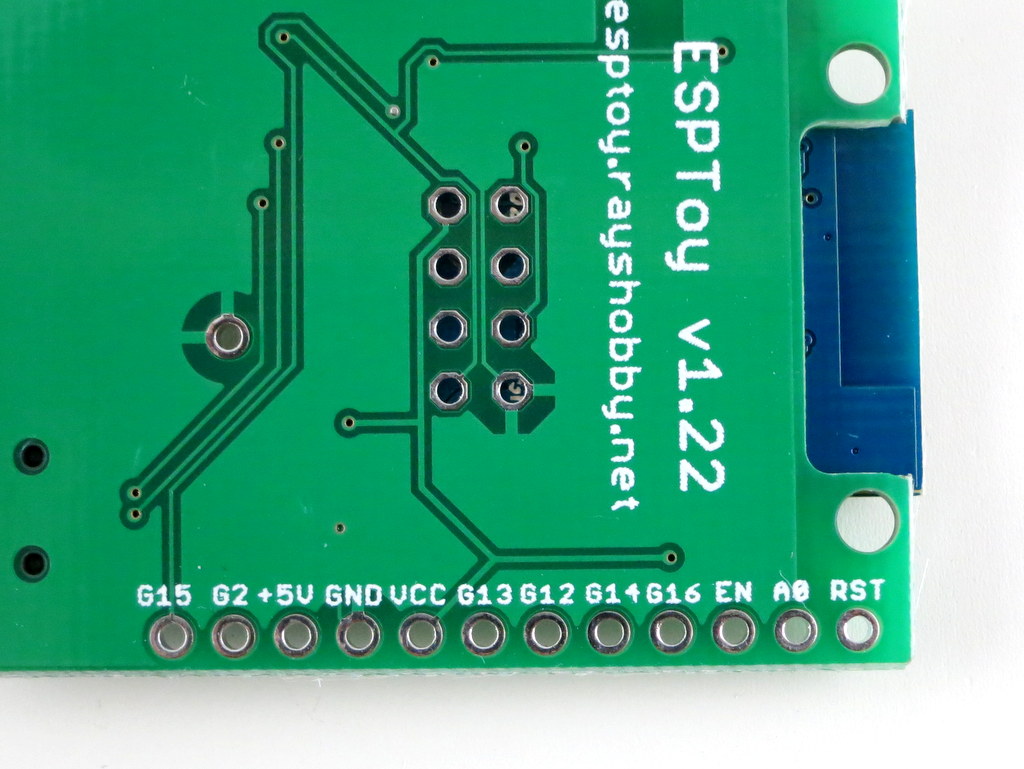
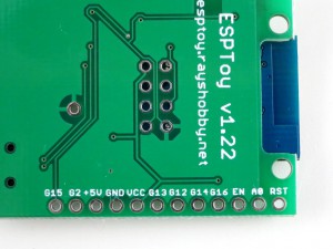
The silkscreen above the breadboard pins marks the pin numbers defined by the Lua firmware. There is one ADC pin (A0) and six general I/O pins (0, 5, 6, 7, 5, 4, 8). In case you want to try a different firmware, and need to know the hardware GPIO pin numbers, just check the silkscreen at the back of the circuit board — those names refer to the hardware GPIO pin numbers. For example, G15 refers to GPIO15. Check the image on the right above.
Another change, as you may have noticed, is that there is no LDO anymore. I got burned by a batch of 3.3V LDOs which aren’t outputting enough current. This lead to some unstable behavior (e.g. ESP8266 restarting etc.). Because ESP8266 can draw a high amount of instantaneous current, the LDO needs to be sufficiently powerful. In this new design, I’ve simply used two diodes to drop the voltage from 5V to about 3.6V (each diode drops 0.7V). In practice, since the USB voltage is often lower than 5V, the VCC is somewhere between 3.2V to 3.6V, which is within the operating voltage of ESP8266. This seems to work quite well, and I’ve not had any power-related issue so far.
I’ve recently used ESPToy at a school workshop. Students really liked it. I was quite concerned with launching 20 WiFi networks in the same room — however, it worked quite well and everyone was able to get the WiFi-controlled color LED demo to work. Given the success of ESPToy, I have been working on redesigning SquareWear as well, to make a special version called SquareWear WiFi, also based on ESP8266. More updates on that will come soon!