“Alexa, Open Sprinkler Zone 1” — How to Use IFTTT with OpenSprinkler (and OpenGarage)

I just discovered something exciting recently and want to share with you: it’s now possible to use IFTTT with OpenSprinkler and OpenGarage; and because IFTTT support Amazon Echo (Alexa), you can now speak voice command to trigger sprinkler actions. For example, say ‘Alexa, trigger open sprinkler zone 1‘, or ‘Alexa, trigger my garage door‘. I will briefly walk you through the setup process. We will be building support for IFTTT into the firmware soon, to allow for additional features like push notification. For now, the guide below will allow you to trigger actions on OpenSprinkler and OpenGarage with your existing firmware.

Before I proceed, I should give credits to Mike Szelong, who has purchased both OpenSprinkler and OpenGarage, and made both work with Alexa through IFTTT. Thanks to Mike for sending me this tip in the first place. Below let me first explain how IFTTT works.

What is IFTTT?
If you’ve never heard of IFTTT, it stands for If This Then That. With IFTTT, you can set up what’s called ‘recipes’, which hook up ‘triggers’ with ‘actions’. There are many triggers, for example, weather changes, sensor value changes, a new text message, a new twitter message, a new photo upload, or in our case, an Alexa phrase. There are also many actions, for example, send a text message, send an email, post a message on facebook, or in our case, send an web request to OpenSprinkler. With IFTTT, you can easily set up recipes like: ‘if temperature drops below xx degrees, send me a text message’, ‘if there is a new post on my facebook, send me a push notification’, or in our case ‘if Alexa receives a specific phrase, trigger a sprinkler action’. Because it’s so convenient, it has become very popular among Internet of Things.

How does IFTTT send or receive web requests?
IFTTT provides support to what’s called a ‘Maker Channel’, allowing you to use generic web requests (i.e. HTTP commands) as triggers and/or actions. This makes it possible to extend IFTTT support to your own DIY hardware gadgets. For example, to use a Maker trigger, just have your gadget send a web request to IFTTT, and hook it up with an action, such as text message, to enable push notification. This way, when OpenSprinkler starts to run any program, or receives weather changes, it can send a web request to IFTTT, which further triggers a text message or push notification to your phone. Conversely, to use a Maker action, you can set IFTTT to send a web request to your gadget. This way, when it receives an associated trigger, it can send a command to OpenSprinkler to start an action. As both OpenSprinkler and OpenGarage implement HTTP GET commands, they can naturally work with IFTTT through the Maker channel.

Wait, what’s the catch?
There are two. First, to use the device as a trigger, the firmware needs to connect to IFTTT. Neither OpenSprinkler nor OpenGarage has firmware support currently to send web requests to IFTTT, you can’t use them as a trigger yet, but work is underway to add such support to the firmware. Second, to use the devices for action, IFTTT needs to reach the device from the Internet. This requires you to set up port forwarding so that IFTTT can use the public IP address to reach the device. I know that port forwarding is gradually phasing out in favor of cloud-connected devices, but for now we will have to stick with port forwarding.


Now I have explained how IFTTT works, let’s go ahead and create some recipes.

Step 1. Sign up for an IFTTT account
Go to ifttt.com, click on ‘Sign up’ to register an account. You will walk through a simple tutorial to learn the basics of IFTTT.

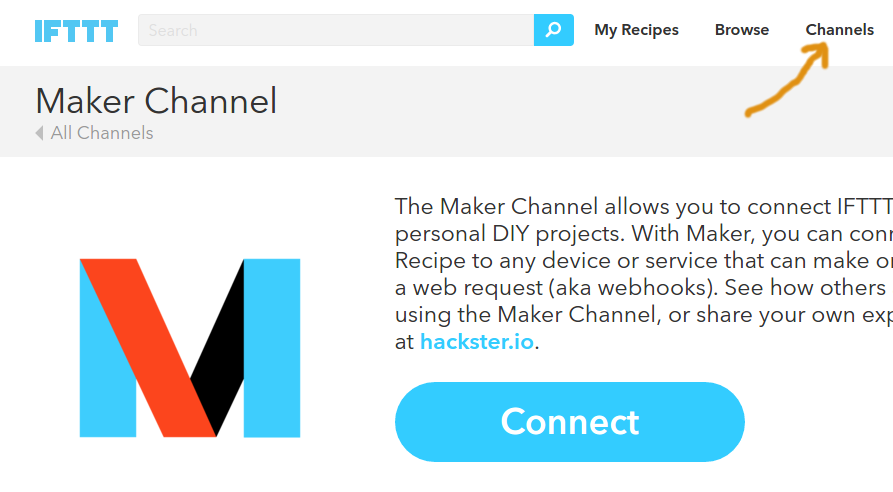
Step 2. Enable Maker channel
Click on ‘Channels’ at the top, then search for ‘Maker’ and under ‘Developer Tools’ select the Maker channel, and click on ‘Connect’. You will be assigned a ‘key. At the moment you don’t need the key, so you can ignore that for now.

ifttt1

Step 3. Set up a recipe
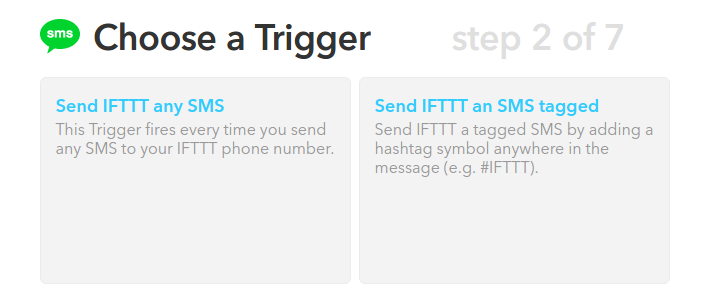
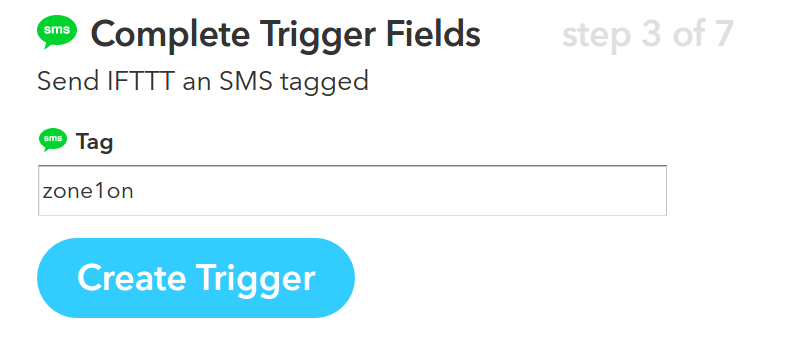
Click on ‘My Recipes’ at the top and then ‘Create a Recipe’. Select a trigger (i.e. this) — for example, search ‘sms’ and select SMS as a trigger. Input your phone number and a verification pin. Then select a trigger method, such as ‘Send IFTTT an SMS tagged’. Then input the tag phrase, such as zone1on. This means every time IFTTT receives a text message with that particular phrase, it will trigger an action.

ifttt2ifttt33

Next, to choose an action (i.e. that), search for ‘Maker’, and click on ‘Make a Web Request’. This is where you need to input the HTTP command. You will need to type in your home network’s external IP address, external port number (that maps to OpenSprinkler through port forwarding), followed by a supported HTTP command (check API document listed below), device password, and required parameters. The example below turns on zone 1 (i.e. sid=0) for 10 minutes (i.e. 600 seconds). For ‘Method’, select ‘GET’, and you can leave Content Type and Body empty. If you are not sure whether the command works or not, simply copy and paste the URL you constructed to a browser, and if the returned message has {‘result’:1} that means it has succeeded.

ifttt5
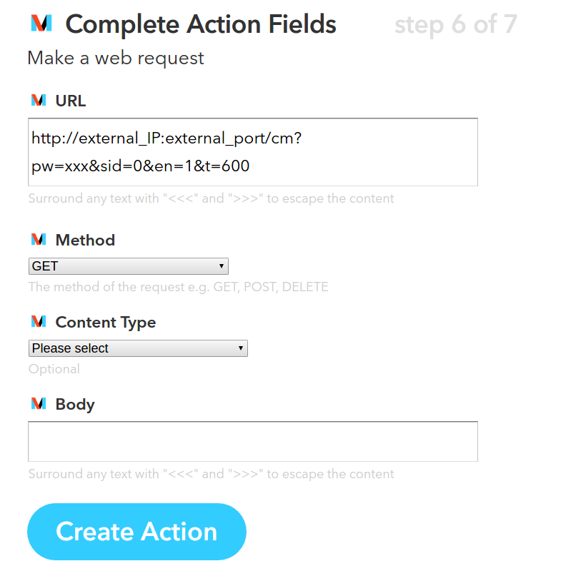
Click on ‘Create Action’ to finish.

In case you’ve got lost, here are some useful links that you may need to refer to:

Step 4. Test the recipe
To test the above example recipe, send a text message #zone1on (don’t forget the pound sign!) to the IFTTT phone number (this is the same phone number you received a text from when you verified your phone with IFTTT). If everything is set up correctly, your sprinkler zone 1 will start watering for 10 minutes!

Step 5. Use Alexa to enable voice command
Now that I’ve walked you through a basic example, you can experiment with using Alexa to enable voice command. You obviously need to have an Alexa (Amazon Echo) for this to work. The recipe is largely the same as the above text message example, except that for trigger (i.e. this) you will select Alexa, and give it a phrase. Now when you speak that phrase to Alexa, it will trigger the action. How exciting! Don’t forget that you need to say ‘Alexa, trigger xxx’ where xxx is the phrase. The ‘trigger’ keyword is kind of like the pound sign in the text message.

If you have an OpenGarage, you can also follow the OpenGarage API to set up web requests and get Alexa to open / close the garage door for you.

Currently as the phrase is fixed / static, there is no easy way to parametrize the phrase. For example, you can’t say ‘trigger open zone 1 for blah minutes’ where ‘blah’ is a variable like 10, 20 or any positive integer you want. I am sure this would be possible in the future though.

Next Step: Notifications
As I said, another popular use of IFTTT is for email / text / push notifications. For doing so, the device needs to send HTTP commands to IFTTT. Upon receiving the request, it can trigger an action such as sending you an email or text message. Work is under way to add this support to both OpenSprinkler and OpenGarage firmware, and hopefully they will be ready soon!

Introducing OpenGarage: an Open-Source WiFi Garage Door Opener

News and Updates

  • We’ve recently found a technical issue with Blynk’s QR code scan feature that makes the Blynk app not work properly on some iOS devices. The symptom is that the app can receive push notifications but the distance value, read count, and LCD widget are not updating. Please check this forum post for solutions. This seems to only affect iOS devices.
  • OpenGarage User Manual (PDF) is available on Github.
  • OpenGarage Firmware 1.0.4 API document is available on Github.
  • Blynk connection issue: recently Blynk updated their cloud server, causing Blynk app to not be able to communicate with OpenGarage. The solution is to update OpenGarage firmware to 1.0.4.
  • Reboot cycle issue: we’ve found a few reports of ‘reboot cycle’ where the controller continuously reboots. This issue has finally been sorted out. The solution is to reflash the firmware using a microUSB cable.


Today I am very excited to introduce you to OpenGarage — an open-source, universal garage door opener built using the ESP8266 WiFi chip and the Blynk app. I’ve wanted to finish this project for a while, as there have been multiple occasions where I left the house in a hurry and forgot to close my garage door, or locked myself out of the house, or had to let a friend or handyman in while I was away. Having a WiFi-based garage door opener (which I can access remotely using my mobile phone) would be super convenient. Recently as I started learning about ESP8266, I found it to be the perfect platform to help me complete this project.

A quick note: this blog post is temporarily the main landing page of opengarage.io. A more professional-looking site is under construction and should be ready soon. Also, the first production run has been ordered, and they should be ready to ship in 2 weeks of time. If you are interested in OpenGarage, you can place your order at rayshobby.net/cart/og.

Here is a video introduction that gives you a quick walk-through:

Here are some head shots of the OpenGarage controller:

IMG_1068IMG_1069

IMG_1007IMG_1070

I made the prototype version using a 3D printed case, and the final version using an off-the-shelf case with custom cutouts. Two pictures of the circuit board are shown on the right above. With OpenGarage, I can now check my garage door status wherever I am, open or close the door remotely, and check the record of recent events through the log and history graph. The controller supports a built-in web interface with embedded HTMLs, and remote access through the Blynk app. The built-in interface is used for local access and changing configuration/settings, while the Blynk app is used for remote monitoring and control.

Hardware-wise, it’s really simple. It consists of:

  • an ESP8266 (WROOM-2) WiFi chip;
  • an ultrasonic distance sensor (HC-SR04);
  • a relay (for triggering garage door actions);
  • a pushbutton and indicator LED;
  • a microUSB connector and CH340G USB-serial chip.

Mounting. The controller is typically mounted to the ceiling at the garage, with the distance sensor facing down. When the garage door is closed, it reads the distance to the ground, or the top of your car if you’ve parked in the garage. When the door opens and comes up, the sensor reads the distance to the door, which is a much smaller value. So by checking the distance value, it can tell if the door is open or closed. The distance value can also tell you if your car is parked in the garage or not, which is an additional benefit that can be useful at times.

For roll-up garage doors, the ceiling mount would not work. Instead, you can mount it to the side of the door, with the sensor facing the outside. This way the logic is reversed: if the distance reading is small, it means the door is closed, and vice versa.

Interfacing with Garage Door System. OpenGarage uses a relay to simulate door button clicks. For most garage door systems, you can simply connect the two wires from the OpenGarage controller to where you would normally insert your door button wires into. The only exception is the most recent Security+ 2.0 systems, which come with a yellow learn button and antenna. These openers use secure door button codes, but you can still interface with them through a compatible door button.

IMG_1066IMG_1009IMG_1008IMG_1073

Alternatively, you can take apart an existing garage door remote, solder two wires to the button, and connect these two wires to OpenGarage. This way, the relay clicks simulate pressing the button on the remote. As long as you have a remote that works with your garage door system, this approach would always work.


Web Interface and Blynk App. The controller has a built-in web interface with embedded HTMLs, implemented using JQuery Mobile. It’s used for WiFi setup, local access (directly using IP) and changing configurations/settings. The controller also supports remote access through the Blynk app, which is a cloud-based service that’s really easy to use. Before proceeding, it’s recommended that you install the Blynk app, create an account, log in, and scan the OpenGarage app QR code to replicate the project inside Blynk. Then go to the project settings and copy the authorization token (32-digit hex code). This way, immediately after the setup step, you can use Blynk to access OpenGarage.

1_og_ap2_og_home3_og_log4_og_options6_og_blynk_app

Initial Software Setup. OpenGarage is powered by a microUSB cable. At factory default settings, it boots into Access Point (AP) mode, creating an open WiFi network named OG_xxxxxx (where xxxxxx is the last 6 digits of MAC). Use your phone or a computer to connect to this network, and then open a browser and type in 192.168.4.1 to access the AP homepage. You will see a list of nearby WiFi networks scanned by the controller. Select (or manually type in) the ssid, input the password, and paste the Blynk token (if you don’t have it, just leave it empty). Then click on ‘Connect’. The controller will go into AP+STA mode, attempt to connect to your router, and report back its assigned IP address.

Once connected, it will reboot into STA-only mode. At this point, switch your phone back to your home WiFi, and click the redirect button (or manually type in the assigned IP) to access the device homepage.

LED and Button Functions. The LED serves mainly as an indicator: in AP mode, the LED blinks rapidly; and in station mode, the LED blinks briefly when the controller reads the distance sensor, which is once every few seconds (configurable). The button (connected to GPIO0) has the following functions: a short click triggers a relay click; and a long press triggers a factory reset (see below). The button can also be used to enter bootloading mode: if the button is pressed when the controller is powered on, ESP8266 will enter bootloading mode. This is useful if you want to upload a firmware through USB (instead of using OTA update).

Reset to Factory Default. At any point, you can press and hold the pushbutton for 5 seconds or more until the LED stays on, then release the button to reset the controller back to factory default.

Built-in Web Interface. At the homepage you can check the distance readings, door status, and a read count value which increments every few seconds as the controller reads the distance sensor. The read count is basically a ‘heart beat’ that indicates if the controller is communicating with your browser or not. You can trigger a button click or reboot the controller. These actions are protected by a device key, which is by default opendoor.

Click the Options button to open the ‘Edit Options’ page. Most of these are pretty obvious. The one you may need to tweak is the distance threshold, which the controller uses to tell if a door is open or closed. Basically, measure the distance from the sensor to the door (when it’s fully open), and that to your car, and pick a value in between the two. The settings are all saved in a configuration file in the flash memory, so they won’t get lost when the power is down.

At the homepage, click the Log button to open the log page. There you can see the list of recent events. The homepage also shows the current firmware version. Next to the version number is an ‘Update’ button, which allows you to upload a new firmware through the web interface (thanks to the OTA update feature available to ESP8266).

Blynk App. For remote access, the Blynk app is really easy to use. Once you’ve set a token, OpenGarage will communicate with Blynk’s cloud server and report its status. Like the built-in web interface, the app allows you to check distance readings, door status, and trigger a button click. Additionally, it provides a history graph that visualizes previous events, and push notifications when the door opens or closes (note that Blynk limits push notifications to no more than one per minute).


Resources and Technical Details

I’ve published the hardware design files and firmware code in Github. Those who are interested in the technical details can go to:

to find out all the low-level details. These include the circuit schematic and PCB (in EagleCAD format), 3D model of the enclosure, OpenGarage Arduino library, and instructions to compile the firmware. If you are interested in modifying the 3D printable enclosure, go to tinkercad.com, log in, and search for ‘OpenGarage’ and you should find the 3D model I created there.

og1.0enclosure

If you want to extend the functionalities of OpenGarage, there are several spare pins which are mapped out on the PCB for adding additional sensors etc.

Overall it has been a very pleasant experience using ESP8266 for this project. It’s inexpensive, powerful, and has active community support. I can’t think of any reason why not to use it for all my future projects 🙂

If you are interested in buying OpenGarage, you can place your order at rayshobby.net/cart/og.


FAQ

Q: How do I update OpenGarage firmware?
A: Compiled firmwares are all released on
OpenGarage github. For example, here is the direct link to firmware 1.0.4:
https://github.com/OpenGarage/OpenGarage-Firmware/raw/master/Compiled/og_1.0.4.bin
Before proceeding, note that once a new firmware is uploaded, the log will be erased, so keep a copy of the log if you need.

  • Use the web interface to update firmware (click the ‘Update’ button at the bottom of the homepage or Options page).
  • If the built-in web interface is not responding, do a factory reset (i.e. pressing the button for 5 seconds or more), then follow the setup steps but leave the cloud token empty (to avoid any potential Blynk connection issues). Once firmware is updated, go to the Options page and put in the Blynk token, make sure the Accessibility is set to ‘Direct IP + Cloud’.
  • If neither of the above work, you can use a USB cable to flash a new firmware (see instructions below).

After updating firmware, check the bottom of the homepage and make sure the firmware version is correct.


Q: How do I reflash the firmware using a microUSB cable?
A: In the event that the controller cannot boot correctly (such that you can’t have access to over-the-air update), you can reflash the firmware via a microUSB cable.

Step 1: Driver. Depending on your operating system:

Step 2: Bootloading mode and serial port.
Let the device enter bootloading mode. To do so, get a microUSB cable, plug the smaller end to the device’s USB port, then press and hold the pushbutton while plugging the cable’s other end to your computer. The LED light should stay on constantly, and you should not hear any buzzer sound. If not, unplug the USB cable and redo this step.

Next, the device should appear as a serial port and you need to find out the serial port name:

  • Windows: the serial port name is COM? where ? is a number. You can find out the port name in the notification area, or in Device Manager — Serial Port.
  • Mac OSX: the serial port name is /dev/tty.wchusbserial? where ? is a number. You can find out the port name by running ls /dev/tty.wch* in Terminal (i.e. command line).
  • Linux: the serial port name is /dev/ttyUSB? where ? is a number. Run ls /dev/ttyUSB* in command line to find out.

Step 3: Reflash firmware.

Download the OpenGarage reflash package and unzip it. The package includes esptool, nodemcu firmware, and OpenGarage firmware. Open a Terminal (i.e. command line window), cd to the folder where you unzipped the package. Depending on your operating system, run the following command (assuming the device is in bootloading mode):

  • Windows: esptool.exe -cd ck -cb 230400 -cp COM? -ca 0x00000 -cf nodemcu.bin
    where COM? is the serial port name you found in Step 2 above.
  • Mac OSX: ./esptool_mac -cd ck -cb 230400 -cp /dev/tty.wchusbserial? -ca 0x00000 -cf nodemcu.bin
    where wchusbserial? is the serial port name you found in Step 2 above.
  • Linux: sudo ./esptool_lin32 -cd ck -cb 230400 -cp /dev/ttyUSB? -ca 0x00000 -cf nodemcu.bin
    where ttyUSB? is the serial port name. If you use Linux 64-bit, use sudo ./esptool_lin64 instead.

If you encounter any error, check if the device is in bootloading mode. Repeat Step 2 to enter bootloading mode before flashing.

Finally, once the nodemcu firmware is flashed, re-enter bootloading mode (Step 2) and run the above esptool flashing command again, except replacing nodemcu.bin at the end with og_1.0.4.bin. This completes the firmware reflashing.


Introducing ESPToy 1.21 (with LiPo charger)

Since the first version of ESPToy, I’ve done some pretty rapid revisions. This post is to introduce the new minor revision 1.21, with LiPo battery jack and charger. As you can see in the annotated diagram below, the main components are the same as ESPToy 1.2: a color (RGB) LED, pushbutton (wired to GPIO0, so it can be used to bootload but also function as a general-purpose pushbutton), a surface mount ESP8266 module, CH340G USB-serial chip, mini-USB port, and breadboard pins. The ESP8266 module is pre-flashed with the latest Lua firmware, and a start-up demo (WiFi-controlled color LED). You can use the pushbutton to re-flash the firmware if necessary. The newly added components are the LiPo battery jack, charging chip (TP4054), and indicator LED.

esptoy121_annotatedIMG_0768

The LiPo jack and charger are due to popular requests. Since many users want to power the ESPToy with a LiPo battery, and make a standalone gadget, it makes perfect sense to add a LiPo jack. It also make sense to throw in a LiPo charging chip (the same as used on SquareWear and AASaver), to automatically charge the battery whenever a USB cable is plugged in. There is a green indicator LED which will turn off when charging is completed. The charging current is approximately 200mA.

The silkscreen above the breadboard pins marks the pin numbers defined by the Lua firmware. There is one ADC pin (A0) and six general I/O pins (0, 5, 6, 7, 5, 4, 8). In case you want to try a different firmware, and need to know the hardware GPIO pin numbers, just check the silkscreen at the back of the circuit board — those names refer to the hardware GPIO pin numbers. For example, G15 refers to GPIO15. Check the image on the right above.

IMG_0766IMG_0767

Another change, as you may have noticed, is that there is no LDO anymore. I got burned by a batch of 3.3V LDOs which aren’t outputting enough current. This lead to some unstable behavior (e.g. ESP8266 restarting etc.). Because ESP8266 can draw a high amount of instantaneous current, the LDO needs to be sufficiently powerful. In this new design, I’ve simply used two diodes to drop the voltage from 5V to about 3.6V (each diode drops 0.7V). In practice, since the USB voltage is often lower than 5V, the VCC is somewhere between 3.2V to 3.6V, which is within the operating voltage of ESP8266. This seems to work quite well, and I’ve not had any power-related issue so far.

I’ve recently used ESPToy at a school workshop. Students really liked it. I was quite concerned with launching 20 WiFi networks in the same room — however, it worked quite well and everyone was able to get the WiFi-controlled color LED demo to work. Given the success of ESPToy, I have been working on redesigning SquareWear as well, to make a special version called SquareWear WiFi, also based on ESP8266. More updates on that will come soon!

Introducing ESPToy 1.2 (with Lua Firmware)

A little while back I released the very first version of ESPToy — a ESP8266 Development Board with a few useful on-board components like color LED, button, and temperature sensor. It has a built-in ATmega644 microcontroller, and pin headers for plugging in a ESP-01 through-hole WiFI module. Shortly after that, I discovered the Lua firmware (named nodemcu) for ESP8266. At first I didn’t pay much attention — Lua is a new language that I’ve never used before, and I wasn’t sure if it’s worth my time learning about it. At the same time I was getting tired of the AT firmware (the original firmware that comes with ESP), partly because it’s not very stable, and partly because it’s complicated to use and involves an extra microcontroller to communicate with it.

Over time I saw increasing development and community support on the Lua firmware. So I became more curious. The final push came recently: there was a supply chain problem of the ATmega644 microcontroller. I was about to purchase a new batch of ESPToy 1.1, but the microcontroller is difficult to source from my suppliers in China. I decided that I should give the Lua firmware a try — if it works, I don’t have to use an extra microcontroller any more!

That’s where I wish I had known it earlier — the Lua firmware is, in my opinion, all around better than the AT firmware. It’s easy to use, especially for writing simple web servers; it’s more stable, and best of all, it runs Lua scripts directly on the ESP module, removing the need to use an extra microcontroller. So here comes ESPToy 1.2, with a surface mount ESP8266 module, pre-flashed with the Lua firmware and a start-up demo (WiFi color LED demo):

Built-in Components. Similar to the previous versions, ESPToy 1.2 has a built-in color LED, pushbutton, mini-USB port and the CH340G USB-serial chip. The pushbutton is internally wired to GPIO0 and can be used to re-flash the firmware if needed. The way Lua firmware works is that you send scripts to it through the serial port. The module will execute the script on the fly, and return results (if any) back to the serial port. This is different from a standard microcontroller program in that the scripts are interpreted (not compiled ahead of time), much like how Javascript, Python, and other scripting languages work. This provides a lot of flexibility, including receiving and running a dynamic script on the fly!

IMG_0716server_example

Pin Definitions. ESPToy 1.2 internally assigns the following pins for the built-in components:

  • Lua pin 2 (hardware GPIO4): Red LED
  • Lua pin 1 (hardware GPIO5): Green LED
  • Lua pin 4 (hardware GPIO2): Blue LED
  • Lua pin 3 (hardware GPIO0): Button (active low)

Note that these pin names refer to the pin indices defined by the Lua firmware. These are different from the hardware GPIO pin numbers.

One big advantage of the Lua firmware is that it runs directly on the ESP microcontroller, removing the need for an extra microcontroller. This simplifies the hardware design and reduces cost. The module comes with 1 analog pin and several digital pins. It can do most things that an Arduino can, such as writing and reading a GPIO pin, reading an analog sensor, PWM, I2C, SPI, UART. But what it really excels is the capability of creating web services and handling WiFi connections. It also has a file system, storing scripts and data directly to the built-in flash memory. This is a huge advantage over Arduino, and it’s pretty much an all-in-one solution to build Internet of Things (IoT) gadgets. Probably the only disadvantages would be the relatively small number of available pins, particularly analog pins, and that the PWM speed is quite low. Other than these, most Arduino applications can be easily adapted to Lua scripts, but now with WiFi capability!

Lua 101. So what’s the catch? Well, learning a new language is a barrier. Lua is similar to C++ and Java, but it’s after all different, and the syntax is quite flexible, so some code may look obscure at first. To begin, the Hello-World example is pretty trivial:

print("Hello ESPToy!")

notice that unlike C++ and Java, there is no semi-colon at the end. Next, we can blink the LED on ESPToy by:

led=2
gpio.mode(led, gpio.OUTPUT)
gpio.write(led, gpio.HIGH)
tmr.delay(1000000)
gpio.write(led, gpio.LOW)

On ESPToy, the red LED is connected to GPIO2, green to GPIO1, and blue to GPIO4. The above lines are very much similar to Arduino code. Note that just like Python and Javascript, you don’t need to define variable types — the variable types are determined dynamically, so it’s quite flexible. Here is an example of a for loop:

led=2
gpio.mode(led, gpio.OUTPUT)
for i=1,10 do
  gpio.write(led, gpio.HIGH)
  tmr.delay(20000)
  gpio.write(led, gpio.LOW)
  tmr.delay(200000)
end

Next is a demo of using interrupt:

led=2
button=3
gpio.mode(led, gpio.OUTPUT)
gpio.write(led, gpio.LOW)
gpio.mode(button, gpio.INT)
function button_cb(level)
  if level==0 then
    gpio.write(led, gpio.HIGH)
  else
    gpio.write(led, gpio.LOW)
  end
end
gpio.trig(button, "both", button_cb)

This sets up an interrupt for GPIO3 (connected to button), which triggers a call back function when the button is clicked. Lua supports anonymous inline function, similar to JQuery. So you can also write the code this way:

gpio.trig(button, "both", function(level)
  if level==0 then
    gpio.write(led, gpio.HIGH)
  else
    gpio.write(led, gpio.LOW)
  end
end)

If anonymous functions are new to you, this can look a bit weird. But you will quickly get used to it, and find it convenient.

WiFi Web Server 101. While the above examples replicate what an Arduino can do, the power of ESP is in its WiFi capability and creating web services. For example, the following code creates a WiFi access point named ESPToy-xx (where xx is the last byte of the MAC address) with password opendoor:

wifi.setmode(wifi.SOFTAP)
cfg={}
cfg.ssid="ESPToy" .. (string.sub(wifi.ap.getmac(), 15,17))
cfg.pwd="opendoor"
wifi.ap.config(cfg)

Similarly you can easily set it to run in client mode and log on to an existing WiFi network.

Next, to create a very simple HTTP server, use the following script:

srv=net.createServer(net.TCP)
srv:listen(80,function(conn)
  conn:on("receive",function(conn, payload)
    print(payload)
    conn:send("Hello, ESPToy!")
  end)
  conn:on("sent",function(conn)
    conn:close()
  end)
end)

It creates a TCP server, listening to port 80. Upon receiving a web request, if sends back a simple webpage and closes the connection. Now log on to the ESPToy-xx WiFi, open a browser and type in 192.168.4.1, you will see the webpage returned by the module. If this was to be done with the AT firmware, you would have to use a microcontroller to send commands to ESP, and the code size can easily triple or quadruple the above script. So it’s a total time saver!

File System. Another advantage of the Lua firmware is that it supports a file system. The ESP-12 SMD module has 512KB flash memory space, enough to store many scripts and data files. If this was to be done on the Arduino, you would have to use a SD card shield or EEPROM shield to provide compatible size of storage. So this is yet another invaluable feature.

Using ESPlorer. To work with ESPToy 1.2, I recommend using the ESPlorer software — a Java-based GUI for easily uploading scripts to the ESP module. It supports sending individual commands, saving scripts to files, running script files, removing files. If a script named init.lua exists on the module, the firmware will automatically execute the script upon booting. This is how the startup demo is set to run.

Re-Flashing Firmware. To upgrade the firmware (to newer Lua versions), or to revert back to the AT firmware, you can use the esptool — a Python-based script. Using ESPToy, press and hold the on-board pushbutton while plugging in a mini-USB cable. This will allow the ESP module to enter bootloading mode. Then run esptool to upload a new firmware.

Resources. You can find additional information and examples projects using the Lua firmware from the following websites:

Also, you may want to check a few tutorials of the Lua programming language to get familiar with it.

Purchase Link. In conclusion, this post is meant to be a crash course of the Lua firmware and the basic usage instructions of ESPToy 1.2. This new version of ESPToy is immediately available at the Rayshobby Shop — it replaces the previous version, and is priced at $16 ($8 cheaper than the previous version!). Give it a try, and have fun!

Introducing the ESP8266 WiFi Toy (ESPToy)


Content

ESP8266 — a very low-cost and flexible Serial-to-WiFi module that has gained a lot of popularity recently. It allows any microcontroller to have WiFi capability by simply using serial communication. In a previous blog post, I demonstrated how to use ESP8266 combined with an Arduino to set up a very simple web server. This time I built a standalone gadget for prototyping called the ESP8266 Toy (or ESPToy for short). There is also a more serious web server demo in the end that shows how to serve HTML files from a SD card, and using JSON and AJAX to implement prettier web design.

You should also know that there has been a lot of on-going development for this module. For example, there is a Lua-based firmware for ESP8266, which is quite amazing. Also check out the community forum here.

As usual, a video demo first:

New ESPToy 1.2:

Original ESPToy 1.0/1.1: Youtube Video Link


ESP8266 module and ESP8266 Toy are available for purchase at Rayshobby Store.


Features

New ESPToy 1.2:

  • ESP-12 SMD WiFi module, pre-flashed with Lua firmware and a startup demo script.
  • 3.3V 250mA linear regulator.
  • Programming using the on-board mini-USB port.
  • One color (RGB) LED, one pushbutton (used as a general-purpose pushbutton as well as for re-flashing firmware)
  • Additional pin headers for connecting external components and/or breadboard experiments.

IMG_0716server_example


Original ESPToy v1.0/1.1 (retired)

  • ATmega644 @ 3.3V, 16MHz, with CH340G USB-serial converter and Arduino bootloader.
  • 3.3V 500mA linear regulator.
  • Programming in Arduino using the on-board mini-USB port.
  • One color (RGB) LED, one pushbutton, one reset button. (New on version 1.1: one additional button on ESP8266’s GPIO0 pin, useful for firmware upgrade)
  • One light sensor (LDR), one temperature sensor (TDR).
  • One 2×4 pin header to fit ESP8266.
  • Additional pin headers for connecting external components and/or breadboard experiments.

In essence, the ESPToy 1.0/1.1 is a 16MHz Arduino with some handy built-in components for easy prototyping with the ESP8266 WiFi module. Once programmed, the whole assembly can run on battery. There is also a power MOSFET on board to programmably control the power supplied to ESP. This allows you to cut off power to save battery life.

The reason I picked ATmega644 (instead of ATmega328) is that 644 has two hardware Serial interfaces. I am using one for the bootloader and USB communication, the other dedicated for WiFi. This is quite handy and allows you to use the fast baud rates. Also, 644 has twice as much memory as 328, so it’s suitable for building more complex projects.

esptoy_annotatedesptoy_2


Demos

As shown in the video above, I’ve written a few examples to demonstrate the basic features of the ESPToy:

New ESPToy 1.2:

To upload the demo Lua scripts to ESPToy 1.2, download and run the ESPlorer software. The Serial port baud rate is 9600 (default). You can open a demo script, click on ‘Save to ESP’ to save the script as a file to ESP’s internal flash memory space. The script will run right away after uploading. You can also click on ‘doFile’ to re-run the script.

  • Start-up Demo: every ESPToy 1.2 is pre-flashed with a start-up demo. Plug in a mini-USB cable, the blue LED will blink and the WiFi module will start in access point mode, creating a WiFi network with SSID ESPToy-xx. The password is opendoor. Connect to this WiFi network, open a browser, and type in http://192.168.4.1. Use the sliders to change the LED color, and click on ‘Refresh Value’ to read button status and analog pin value.
  • Hello ESPToy!: shows the Serial print function.
  • Blink LED: shows digital pin write, and delay functions.
  • Button Interrupt: shows how to set up interrupt on a digital pin.
  • Hello ESPToy Server: shows a simple HTTP web server.


Original ESPToy v1.0/1.1 (retired)

  • SearchBaud: this comes handy if you forgot the correct baud rate of your ESP8266. It loops through the common baud rates, sends an empty AT command, the detects the correct baud rate by checking the result.
  • SerialCommand: this demo allows you to send AT commands to ESP8266 through a Serial monitor. Use this demo to experiment with all the AT commands available for ESP8266.
  • ScanNetwork: this demo starts the ESP8266 in AP mode, which creates a local WiFi network (the name is ESPxxxx). Use a smart phone or laptop to log onto this network, then open a browser and type in IP adddress 192.168.4.1. You will see a webpage with a list of detected WiFi networks. Type in the ssid and password of the target network, then click on Connect. The page will redirect in about 10 seconds to show the client IP address of the module on the target network. This is pretty standard approach to get your WiFi-enabled gadget to log on to your target network.
  • WebServer: this is a simple web server demo. It serves a html webpage and uses JSON and AJAX to periodically display the analog pin values. The first two analog pins correspond to the light and temperature sensors respectively, so these two values will respond to light and temperature changes. There are also three sliders to set the color of the on-board LED. As I said before, the demo can run on battery, so this can be used as a WiFi-enabled color LED light. Thinking about a simplified version of the Philips Hue? Yup, this is a poor man’s version of that 🙂
  • WebServer_SD: same as above, except this requires an external SD card slot, so that it can serve bigger and multiple html pages from files stored on the SD card.


Preparation

The ESPToy’s source code is available on Github. Check the README file therein to get started.

Serial Port and Driver:
ESPToy uses a CH340G USB-to-Serial converter. For:

On Windows, the Serial Port name is COM? where ? is a number assigned to the USB-serial chip. On Linux, the Serial Port name is /dev/ttyUSB? where ? is a number. On Mac, the Serial Port name is tty.wchxxx.

Programming ESPToy 1.2

Instructions in this section are being re-organized. For now please refer to the ESPToy 1.2 instructions in this blog post.


Programming ESPToy 1.0/1.1 (retired)
Programming the ESPToy can be done through the Arduino IDE (tested with Arduino version 1.0.6). Because ATmega644 is not a board that appears in the stock Arduino, you will need to copy the atmega644 subfolder (from the hardware folder) to the corresponding hardware folder in your Arduino’s installation directory; same with the ESPToy subfolder (from the libraries folder).

Next, launch the Arduino IDE, select Tools->Board->ESPToy, and the correct Serial port from Tools->Serial Port (see below), then select a program from File->Examples->ESPToy, and finally click on Upload

ESPToy Arduino Library:
The RFToy Arduino library can be downloaded from: http://github.com/rayshobby/esptoy. You can either clone this Github repository, or download it as a zip: https://github.com/rayshobby/ESPToy/archive/master.zip

Pin Assignments:

  • D0: ESP power (active LOW, pulled down by default)
  • D3: push-button
  • D12: red LED (pwm)
  • D13: green LED (pwm)
  • D14: blue LED (pwm)
  • A0: light sensor (LDR)
  • A1: temperature sensor (TDR)
  • Serial: USB serial TX/RX
  • Serial1: ESP8266 TX/RX

Spare Pins: D2 (INT2), D4, D15, A2, A3, A4, A5, A6, A7

Power Options:
ESPToy can be powered by USB or an external battery. There is a battery jack that fits a standard 3.7V lithium battery. In addition, there are two battery pins (next to the battery jack) — you can solder wires to connect a 3V AA/AAA battery pack. Note that the external AA/AAA battery should not exceed 3.6V (because it’s not regulated).


Flashing a New Firmware to ESP8266

Programming ESPtoy with Arduino: I strongly recommend you to learn to use Arduino to program ESPtoy, due to its flexibility and memory efficiency. While Lua firmware is easy for beginners, to write advanced programs, it’s much easer to use Arduino. Check the resources in this forum post.

On ESPToy 1.2 and 1.1: there is a pushbutton button (on version 1.1 it’s at the upper-left corner) — it’s connected to ESP8266’s hardware GPIO0 pin. If this button is pressed when powering up ESPToy, the ESP8266 will enter bootloading mode waiting for a new firmware. I recommend using the esptool python program to upload firmware, which is very easy to use. Specifically, in command line, run
./esptool.py write_flash 0x00000 xxxx.bin
where xxxx.bin is the firmware name.

On ESPToy 1.1, use the SerialCommand sketch to prepare ESPToy as a serial relay.


For ESPToy 1.0 (retired): to let ESP8266 enter bootloader, you need to solder a wire from ESP8266’s GPIO0 pin to ground. Specifically, if GPIO0 is pulled to ground, upon power-up ESP8266 will enter bootloader mode waiting for a new firmware from the Serial interface. In contrast, if GPIO0 is pulled up (to VCC), ESP8266 will boot into normal operation mode.

The picture below shows where the GPIO0 pin and a ground pin (any ground pin on the board should work). The wire should be soldered at the back of the circuit board. You can also connect a switch in series on the wire to easily switch between bootloader mode and normal mode.

esp_gpio0

Once this is done, you can flash the SerialCommand sketch to ESPToy, which will make it serve as a Serial relay. I recommend using the esptool python program to upload firmware, which is very easy to use. Specifically, in command line, run
./esptool.py write_flash 0x00000 xxxx.bin
where xxxx.bin is the firmware name.


Purchase Link


OpenSprinkler Firmware 2.1.1 New Feature: Control Remote Power Sockets

In the past I’ve written several blog posts about how to use Arduino to interface with remote power sockets. For home automation involving powerline devices (e.g. lights, heaters, pumps, fans), this is my favorite solution, because it’s low-cost (remote power sockets are widely available at cheap price) and convenient (no messing around with relays and powerline wires). Also, one Arduino plus transmitter can simultaneously talk to many power sockets, making this a scalable solution too.

With the just released OpenSprinkler firmware 2.1.1, support for interfacing with remote power sockets has finally arrived. So you can now use OpenSprinkler not only to control sprinkler valves, but also powerline devices. Trying to find a programmable way to control your Christmas lights? Look no further! With OpenSprinkler’s easy-to-use web interface and flexible programming capability, you can enable automated control of lights, heaters, pumps, fans — anything that can be plugged into wall outlets.

Here is a quick video tour on how to get started:

Below are detailed instructions.

Required Parts:

How does this work?
Let me briefly explain how the whole thing works. First, common remote power sockets operate in the 433MHz radio frequency band. When you press a button on the remote, it sends out a signal to the power socket, which gets decoded and acted upon. If we can sniff the signal, we can use a microcontroller plus a 433MHz transmitter to replicate the signal, thus be able to directly control the power socket in software. The RFToy is a gadget that I’ve designed to easily decode signals from common remote power sockets. Once we have the code, we can use OpenSprinkler to simulate the code, thus be able to control remote devices.

Heads-up: the following steps require a small amount of soldering. The estimate time for modification is 15 to 20 minutes.

Step 1: Decode Remote Power Sockets
Take out the RFToy, plug in a 433MHz receiver (making sure the VCC and GND pins on the receiver match the +5V and GND pins on the RFToy). Follow the on-screen instructions to record the on/off signal of a power socket. Once decoded, the signal will be converted to a 16-character hexademical code.

To test if the code works, take out the 433MHz transmitter, and solder a 17cm (6.7inch) long wire antenna to the ANT pin. Then plug it into the RFToy (making sure the DATA and GND pins on the transmitter match the DATA and GND pins on the RFToy). Bend the pins as necessary. Now click button S3 or S1 on the RFToy, the power socket should be toggle on or off just like when you press the buttons on the remote. Keep in mind that although most remote power sockets work in the 433MHz band, there are some that work in the 315MHz band. In that case, just use a 315MHz transmitter-receiver pair.

Step 2: Install RF Transmitter to OpenSprinkler
Remove the OpenSprinkler enclosure, and locate the RF transmitter pinouts (marked A3 VIN GND). The pinouts are located either close to the top of the PCB, or next to the Ethernet jack. Plug in the transmitter to the pinouts, making sure the DATA-VCC-GND pins on the transmitter match the A3-VIN-GND pins on the circuit board. Then solder the three pins at the back of the circuit board, and clip as necessary. Carefully arrange the wire antenna around the LCD and re-install the enclosure.

It’s important to use a wire antenna of sufficient length, otherwise the transmission range will be severely limited.

Step 3: Final Testing
Make sure your OpenSprinkler is running firmware 2.1.1 or above. If not, please follow the firmware instructions to upgrade your firmware first. Then go to Edit Stations, select the station you’d like to use as an RF station, and change its name to the 16-character hexademical code recorded on the RFToy. Any station with a name of this form will be automatically recognized as an RF station. When the station is turned on, the controller will automatically send out the signal through the installed RF transmitter, thus turning on the corresponding power socket (and vice versa for turning off the station).

Three quick notes:

  • The normal station function still works (i.e. if there is a sprinkler valve connected to that station, it will be switched on/off accordingly).
  • Most likely you want to turn off the ‘sequential’ flag for RF stations. This is because unlike sprinkler stations, you probably don’t want RF stations to be serialized with other stations.
  • If you are short of stations, just increase the number of expansion boards. You don’t need to have the physical expansion boards (think of RF stations as virtual sprinkler valves). Firmware 2.1.1 supports up to 48 stations in total.

With this feature, you can now use OpenSprinkler to programmably switch a large number of powerline devices, such as Christmas lights, landscape lights, water pumps, heaters, fans.

Keep in mind that because this is still an experimental feature, don’t use it on anything critical (i.e. those that can cause damages if accidentally left on). Depending on the distance and obstacles between OpenSprinkler and remote power sockets, it might not reliably switch on/off power sockets. So take time to do plenty of testing before you finalize the setup.

os_rf_install

That’s it. We encourage you to try out firmware 2.1.1 and let us know your comments / suggestions / feedback. Don’t forget to post pictures of your projects. We would greatly appreciate your efforts. Thanks!

First Impression on the ESP8266 Serial-to-WiFi Module


Check my new blog post on the ESP8266 Toy


Continuing from my previous blog post about Hi-Link HLK-RM04 module, I have finally received the ESP8266 Serial-to-WiFi module that I’ve been waiting for. As I said previously, with the popularity of IoT devices, there is an increasing demand for low-cost and easy-to-use WiFi modules. ESP8266 is a new player in this field: it’s tiny (25mm x 15mm), with simple pin connections (standard 2×4 pin headers), and best of all, it’s extremely cheap, less than US$3 from Taobao.com!

IMG_3188IMG_3189IMG_3190

What is Serial-to-WiFi? Simply put, it means using serial TX/RX to send and receive Ethernet buffers, and similarly, using serial commands to query and change configurations of the WiFi module. This is quite convenient as it only requires two wires (TX/RX) to communicate between a microcontroller and WiFi, but more importantly, it offloads WiFi-related tasks to the module, allowing the microcontroller code to be very light-weighted.

There are already a lot of excitements and resources you can find online about ESP8266. I’ve included a few links below:

These are great resources to reference if you need help working with ESP8266. Below I document my own experience. I’ve also bought a few extra and put them available on the Rayshobby Shop for anyone who is interested in buying the module and don’t want to wait for the long shipping time from China 🙂


Check my new blog post on the ESP8266 Toy


Pin Connections. ESP8266 is sold in several different versions. The one I received is the version with 2×4 male pin headers, and PCB antenna. In terms of the form factor, it looks a lot like the nRF24L01 2.4G RF transceiver. Here is a diagram of the pins:
ESP8266_pinout
Connect the top two pins (UTXD, GND) and bottom two pins (VCC, URXD) to the RXD, GND, VCC, TXD pins of a microcontroller. Note that VCC must be no more than 3.6V. The middle four pins are should be pulled up to VCC for normal operation. However, if you need to upgrade the firmware of the module, you need to pull the GPIO0 pin to ground — that way upon booting ESP8266 will wait for a new firmware to be uploaded through serial. This is how you can upgrade the firmware in the future.

A few quick notes for connection:

  • The typical operating voltage is 3.3V (acceptable range is 1.7V to 3.6V). As the module can draw up to 200 to 300mA peak power, make sure the power supply can deliver at least 300mA. For example, the 3.3V line from a USB-serial cable would be barely sufficient, in that case it’s better to use a LDO to derive 3.3V from the 5V line.
  • When using the module with a 5V microcontroller, such as a standard Arduino, make sure to use a level shifter on the URXD pin — a simple resistor-zener level shifter is sufficient. Again, this is to prevent over-voltage.

A schematic will make it clear. See below. In my case, I soldered the components and a matching female 2×4 pin header to a perf-board. This way I can easily plug in and unplug ESP8266. Again, if you are using a 3.3V microcontroller, you can do away with the LDO and zener diode.

esp8266_connIMG_3194

Experiments using a USB-Serial Cable. Before connecting to a microcontroller, it’s a good idea to use a USB-Serial cable (such as the inexpensive PL2303 USB-serial converter) to check out the basic functions of the module. Connect the PL2303 cable with ESP8266 according to the schematic above. Then open a serial monitor (such as gtkterms in Linux and putty in Windows) with 11520 baud rate (my ESP8266 seems to be set to 115200 bard rate; earlier versions use 57600). Then you can use a list of AT commands to talk to ESP8266. The AT commands are pretty well documented on this page. Below are some example input (shown in bold font) and output that show how to reset the module, list available WiFi networks, check the WiFi network it’s connected to, list IP address, and firmware version etc.


AT
OK
AT+RST
OK
ets Jan 8 2013,rst cause:4, boot mode:(3,6)
wdt reset
... ...
chksum 0x46
csum 0x46
ready
AT+CWLAP
+CWLAP:(0,"",0)
+CWLAP:(3,"freefly",-49)
OK
AT+CWJAP?
+CWJAP:"freefly"
OK
AT+CIFSR
192.168.1.130
AT+GMR
00150900
OK

A Simple Demo using Arduino.
Next, I connected ESP8266 to an Arduino. Because Arduino is already using the TX/RX pins for bootloader, make sure to unplug ESP8266 while flashing the Arduino, otherwise you may not be able to upload a sketch successfully. Also, you can’t use TX/RX for printing debugging information, since ESP8266 will be using them to communicate with Arduino. Instead, you can use another pair of pins (e.g. D7 and D8) as software serial pins, and use a PL2303 serial cable to monitor the output. This will help print debugging information.

I’ve also experimented with using software serial to communicate with ESP8266, but that has failed — ESP8266 requires 115200 baud rate, and that’s a little beyond the capability of software serial. So you have to stick with the hardware TX/RX pins.

(Update: the code has been revised on Dec 14, 2014 to improve robustness, particularly for some of the latest ESP8266 firmwares. Right now there is still an issue that if the browser is closed before the transfer is completed, it may leave ESP8266 in the notorious ‘busy s’ mode, the only solution to which is to do a hard reset. If using the module in real products, make sure you have a way to use a microcontroller pin to reset the power of the module, thus providing a way to hard reset the module. It looks like future firmwares may be able to address this in software.)

The demo program first configures ESP8266 to log on to your WiFi network (SSID and password are given as macro defines at the beginning), then it sets ESP8266 as HTTP server with port number 8080, and it listens to incoming request. If you open a browser and type in http://x.x.x.x:8080 where x.x.x.x is the module’s IP address (printed to soft serial pins), you will see the output which is a list of analog pin values, and the page refreshes every 5 seconds. So this is a basic Hello World example that shows how ESP8266 can be configured as an IoT server, responding to incoming requests.

IMG_3193

Challenges. While my initial experiments with ESP8266 have been quite successful, I’ve also encountered minor issues that took me a while to figure out. For example, while the AT commands are well documented, they don’t seem extremely consistent — some commands allow question marks at the end, some don’t. I also see variations of the returned values from running the AT commands: sometimes there is an extra end of line character, sometimes there is none. These basically require a robust software library to handle all possible cases.

Overall I would say ESP8266 is a very promising WiFi module for IoT, particularly open-source IoT gadgets, because of its low cost, compact size, and the community development. It seems the manufacturer has also open source the firmware code, and thus the minor issues can probably be easily fixed through a firmware upgrade.

We have a small number of ESP8266 modules available in stock, and will continue to offer them if there are sufficient interests. Thanks!


Check my new blog post on the ESP8266 Toy


First Impression on HLK-RM04 Serial-to-WiFi Module


Check my new blog post on the ESP8266 Serial-to-WiFi module


As the Internet-of-Things (IoT) are becoming more and more popular, there is an increasing demand for low-cost and easy-to-use WiFi modules. For Raspberry Pi and BeagleBone, you can plug in a cheap USB WiFi dongle (like the popular Edimax 7811). These dongles are generally less than $10. But for microcontroller-based devices, the options are much fewer and generally more costly. For example, an Arduino WiFi shield can easily cost $40 to $50; even the more recent CC3000 module costs about $35. If you are puzzled by the big price difference: those cheap WiFi dongles require a USB host system, which is beyond the capability of Arduino. Still, it’s unsettling to realize that a WiFi module or shield would cost more than an off-the-shelf WiFi router, even though the router is significantly more powerful.

Recently I saw a post on Hack A Day alerting us about a new Serial-to-WiFi chip. I immediately ordered two of those. I honestly don’t know what I should expect from these $3 parts, but perhaps it’s a good push towards a new wave competitions on low-cost WiFi solutions. Anyways, while waiting for the shipment to arrive, it reminded me that a while back I actually bought something similar: a Hi-Link HLK-RM04 Serial-to-WiFi module. It’s about $10, so still pretty low-cost. I am glad I didn’t lose it, so I took it out of a pile of electronics and started experimenting with it.

IMG_0222IMG_0221

As you can see, the module is pretty small (about 40mm x 30mm). The picture on the right above shows the components underneath the metal shield. The chip (RT5350F) is a 360MHz MIPS core with built-in WiFi support. The module is quite powerful — at factory default settings it functions as a normal WiFi router. Now, in order to get it to talk to a microcontroller like Arduino, I need to use its Serial-to-WiFi capability. What is that? Well it means using the serial (TX/RX) interface to send and receive Ethernet buffers, and similarly using serial to send commands to the module and query or change its current status. This is quite convenient because first, it only takes two wires (TX/RX) of the microcontroller to talk to the module, second, it moves WiFI-related tasks to the module allowing the Arduino code to be very much light-weighted.


Check my new blog post on the ESP8266 Serial-to-WiFi module


Power-Up. To start the module you just need to provide +5V power. At the first use, the module boots up into a WiFi AP (access point) named Hi-Link-xxxx so you can actually log on to the WiFi network and change settings there. Here is what the homepage looks like (default IP: 192.168.16.254, default log-in: admin/admin):

hlk_rm04_1

Change Settings. For my purpose I need to set the module as a WiFi client so that it can log on to my home network, and allow the Arduino to communicate wirelessly through the module. So I changed the NetMode to WiFi Client – Serial, and put in my home network’s SSID and password. I also changed the Serial baud rate to 57600 (the default is 115200): the lower baud rate can help Arduino to communicate with it more reliably especially if I am going to use software serial. Make sure that the Local/Remote port number is set to 8080 or anything other than 80 (because 80 is reserved for the module’s homepage).

hlk_rm04_2

Receiving Data. Now after the module boots up, it appears as a device on my home network (for example, 192.168.1.147). If I type in 192.168.1.147 in a browser, I will still see the same homepage as above. However, now I can communicate with the module’s serial interface through port 8080. To see what’s going on, I used a PL2303 USB-serial converter: connect the serial converter’s +5V, GND, TXD, RXD to the WiFi module’s +5V, GND, RX, TX (note TXD->RX and RXD->TX), then I opened a serial monitor at 57600 baud rate (putty in Windows or gtkterms in Linux). Now type in http://192.168.1.147:8080 in a browser, I get the following output on the serial monitor:

GET / HTTP/1.1
Host: 192.168.1.147:8080
Connection: keep-alive
Accept: text/html,application/xhtml+xml,application/xml;q=0.9,image/webp,*/*;q=0.8
User-Agent: Mozilla/5.0 (X11; Linux x86_64) AppleWebKit/537.36 (KHTML, like Gecko) Chrome/37.0.2062.94 Safari/537.36
Accept-Encoding: gzip,deflate,sdch
Accept-Language: en-US,en;q=0.8,zh-CN;q=0.6,zh;q=0.4

Cool, this means the Ethernet buffer has been received through the serial RX pin. If I can then send something back through the serial TX pin, like acknowledgement plus HTML text, the data will be transferred back to the browser. This is basically how HTTP GET command works.

A Simple Arduino Example. To send data back through the serial TX pin, I used an Arduino to set up a simple example. To get reliable communication, I used Arduino’s hardware RX/TX (0/1) pins. The drawback of this is that when you program the Arduino you need to temporarily disconnect the WiFi module from these two pins, otherwise they will interfere with the uploading process. Here is a picture of the setup:
hlk_rm04_3

Next, I wrote an Arduino program to print out the analog values of A0 to A5. This is actually modified from the WebServer example in the Arduino Ethernet Shield library:

void setup() {
  Serial.begin(57600);
}

void loop() {
  boolean has_request = false;
  if (Serial.available()) {
    while(Serial.available()) {char c = Serial.read();}
    has_request = true;
  }
  if (has_request) {
    Serial.println("HTTP/1.1 200 OK");
    Serial.println("Content-Type: text/html");
    Serial.println("Connection: close");  // the connection will be closed after completion of the response
    Serial.println("Refresh: 5");  // refresh the page automatically every 5 sec

    String sr = "\n";
    sr += "

Basically receiving/sending Ethernet buffers is done through reading/writing into serial. Now open a browser and type in http://192.168.1.147:8080, I see the following:

analog input 0 is 521
analog input 1 is 503
analog input 2 is 498
analog input 3 is 510
analog input 4 is 525
analog input 5 is 548

Pretty cool, isn’t it! 🙂 If I have a SD card connected to Arduino, I can also serve files, such as Javascripts or logging data, from the SD card.

Blinking LEDs. By analyzing the received buffer, I can also implement various HTTP GET commands. For example, the program below sets the LED blinking speed by using http://192.168.1.147:8080/blink?f=5 where f sets the frequency.

void setup() {
  Serial.begin(57600);
  pinMode(13, OUTPUT);
}

int f = 0, pos;
void loop() {
  boolean has_request = false;
  String in = "";
  if (Serial.available()) {
    in = "";
    while (true) {  // should add time out here
      while (Serial.available() == false) {}
      in += (char)(Serial.read());
      if (in.endsWith("\r\n\r\n")) {
        has_request = true;  break;
      }
    }
  }
  if (has_request) {
    int i1 = in.indexOf("GET /blink?f="), i2;
    if (i1 != -1) {
      i2 = in.indexOf(" ", i1+13);
      f = in.substring(i1+13, i2).toInt();
    }
    Serial.println("HTTP/1.1 200 OK\nContent-Type: text/html\nConnection: close");
    String sr = "\n";
    sr += "\n";
    sr += "LED frequency: ";
    sr += f;
    sr += "Hz.";
    Serial.print("Content-Length: ");
    Serial.print(sr.length());
    Serial.print("\r\n\r\n");
    Serial.print(sr);
    has_request = false;
  }
  if (f>0) {
    static unsigned long t = millis();
    if (millis() > t + 1000/f) {
      digitalWrite(13, 1-digitalRead(13));
      t = millis();
    }
  }
}

More on Changing Settings. Instead of using the WiFi module’s homepage to configure settings, you can also change settings by sending serial commands to the module directly. This can be done by pulling the RST pin on the module low for a couple of seconds, which switches the chip in AT command mode. Then you can send (through serial) any of the listed AT commands to change parameters such as SSID and password. This is a nice way to add some automation to the configuration process. Details can be found in the module’s datasheet.

Drawbacks. The main drawback of a Serial-to-WiFi module is that the data transfer speed is quite low. I tested transferring a file stored on SD card and am only getting 5 to 7 KB/s. This means to transfer a 1MB file it will take 3 minutes. Clearly not a good solution for bulk data. Another drawback is that if you need to restart the WiFi module it generally takes 35 to 50 seconds to boot up, that can be an issue for the impatient. Fortunately you likely don’t need to reboot the WiFi module frequently.

Overall the HLK-RM04 Serial-to-WiFi module is a reasonable and low-cost solution for adding WiFi to Arduino and similar microcontroller boards. At the price of $10, there is no much more you can ask for 🙂