An EagleCAD Script for Creating Laser-Cut Project Enclosures

When designing electronic circuits, often it’s necessary to have a proper enclosure for the project, to protect the circuit board and components, and for aesthetic reasons. There are several options to choose from. For example, if this is a one-off project, you can pick an off-the-shelf enclosure, make custom cutouts to fit the PCB and its buttons, connectors etc. But you will be limited by the enclosures available on the market, and you have to design the PCB size and screw hole locations according to the enclosure, so it’s not very flexible. You can also use 3D printing to make a custom case that fits the PCB nicely, but 3D printing is generally slow, and cheap 3D printers have poor precision. If you are making a commercial product and need volume production, you can order an injection mold, and the injection-molded enclosure fits the circuit perfectly. But you have to spend costs thousands or tens of thousands of dollars to order the mold, and this upfront cost is too much for small-scale projects.

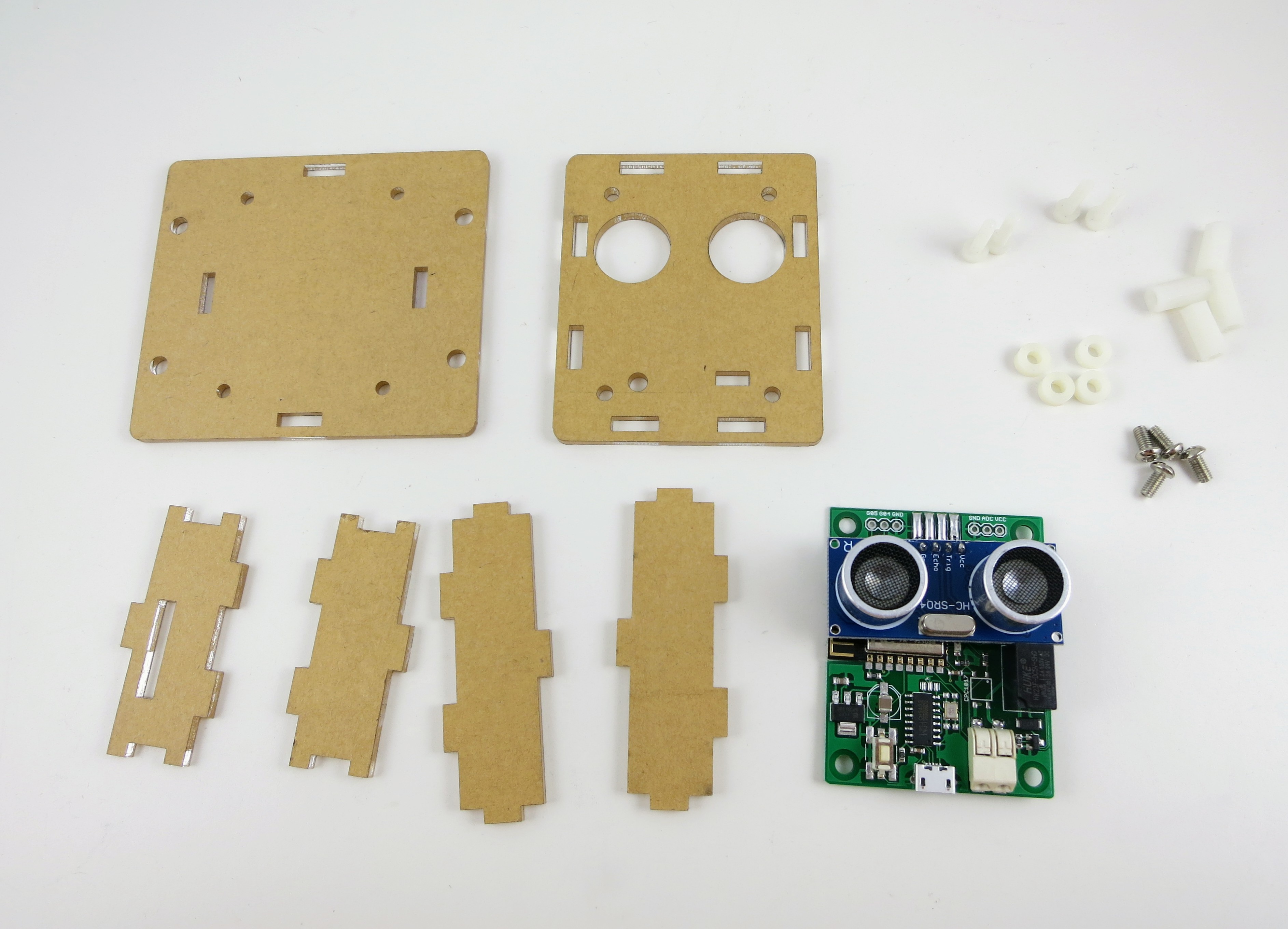
Since last year I’ve been experimenting a lot with laser-cut acrylic enclosures. Compared to the other options, laser-cut enclosures are very easy to customize for the particular PCBs I have designed; they are relatively cheap and fast to make, you can add text engravings to them, and there is no upfront cost. So I have been using laser-cut enclosures a lot for a variety of electronics projects. Generally speaking, the enclosure consists of six pieces of laser-cut acrylic panels, with teeth and holes on the side to lock them together and form a box. You can use plastic or copper screws and pillars to secure the PCB inside the box. As a side benefit of this type of enclosure — if you happen to make a mistake on one panel (which I did a few times), you can just re-order that particular panel so it’s very easy to re-design and correct the mistake.

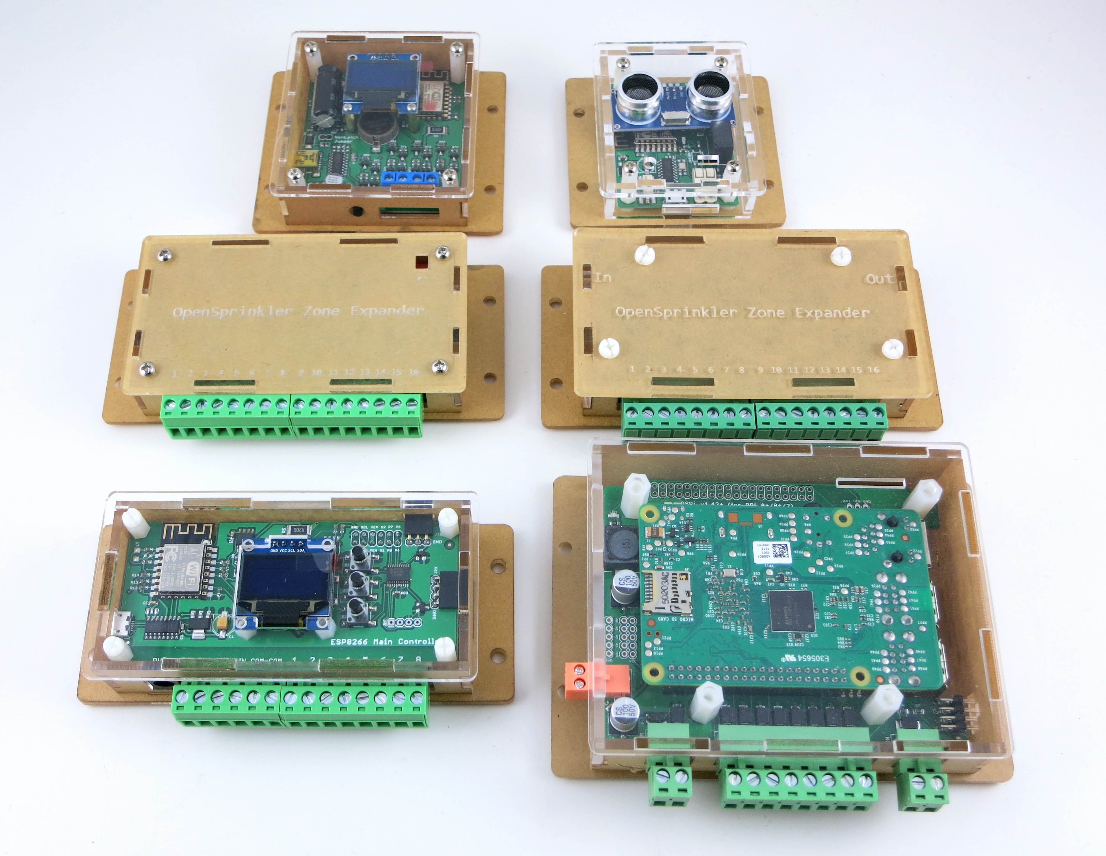
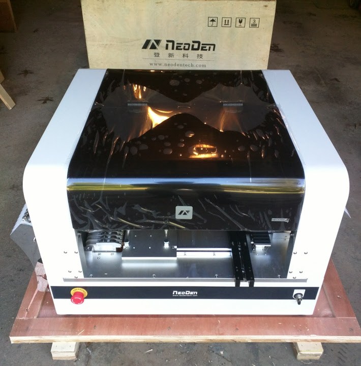
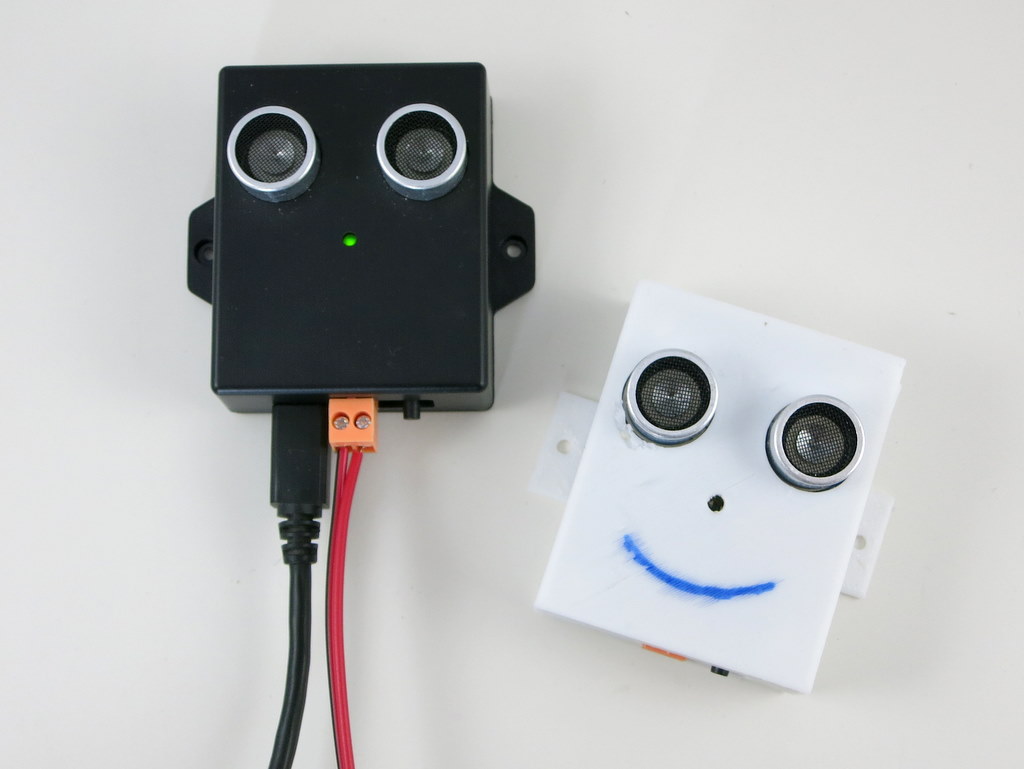
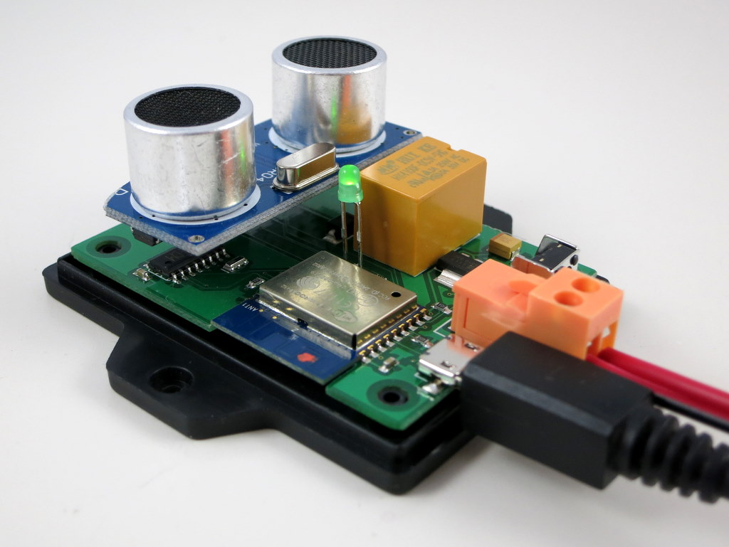
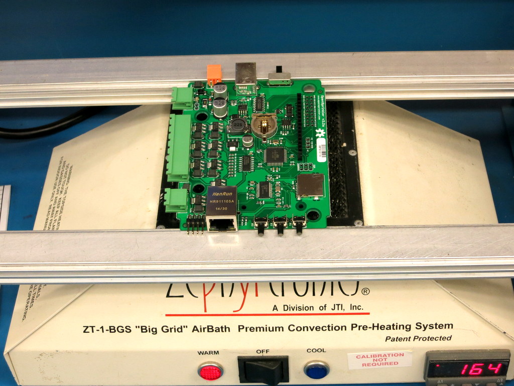
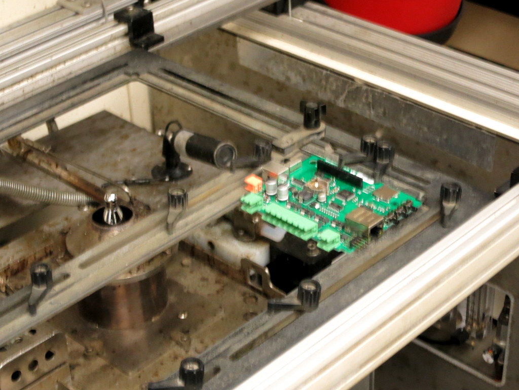
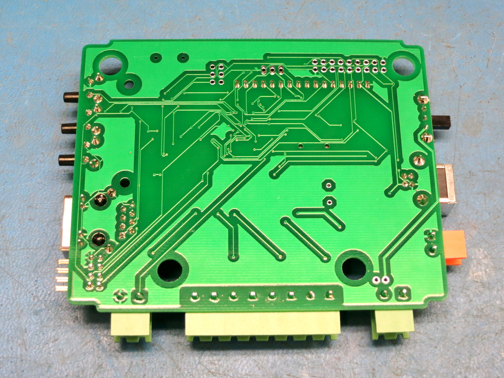
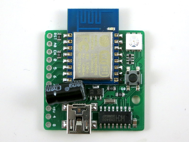
When I started, I found some tutorials and design tools online, to help create the six panels. But they are not really convenient or easy to work with. Because I routinely use EagleCAD to create my circuit boards, it would be really nice to have a enclosure design tool inside EagleCAD, so that I can compare the enclosure with the PCB precisely, making sure that all the cutouts are in the correct locations and have correct sizes. So a little while back, I wrote an EagleCAD script to help me create laser-cut enclosure panels, and used it to create a variety of project enclosures, as shown in the picture below.

Below I will briefly walk through the details of the script, what the various parameters mean, and I made a video to demonstrate how to use this script. To begin with:


Video Tutorial


Explanation of Parameters

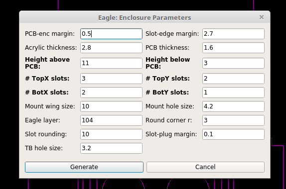
The way this script works is that it follows the dimensions of your PCB outline to create the six panels. It assumes the PCB is rectangular shaped, but if needed you can modify it to support non-rectangular shaped PCBs. There are a number of parameters you need to set, which I will briefly walk through below. Most of them are best explained by the annotated images below. All parameters of lengths are of unit millimeter (mm).

  • PCB-enc margin: the margin from PCB border to enclosure interior border.
  • Slot-edge margin: the margin from the slot boundary to enclosure edge.
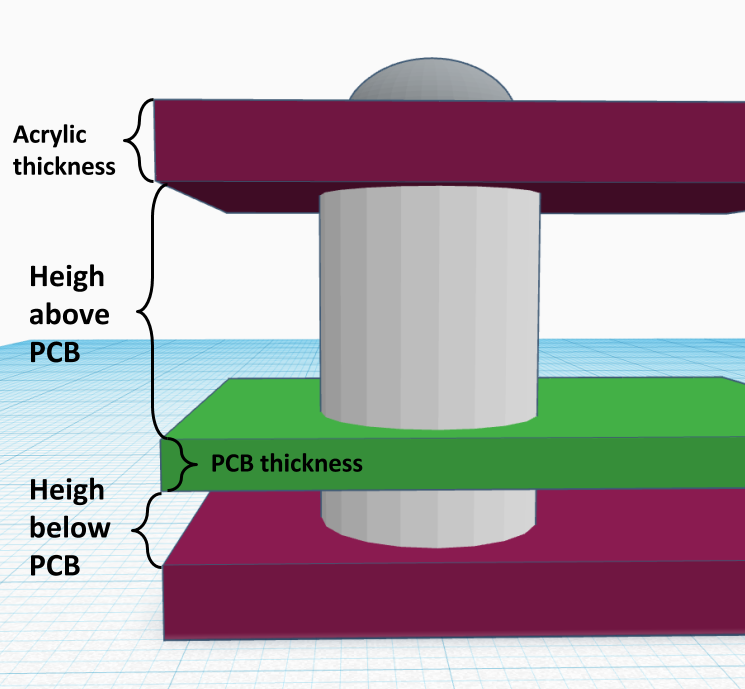
  • Acrylic thickness: the common acrylic material I’ve used are either 2mm thick or 3mm thick. You may have to adjust this slightly according to your supplier’s acrylic material thickness. You may want to make this slightly larger (like 2.1mm and 3.1mm respectively) to account for error and variations in the actual material.
  • PCB thickness: standard PCB thickness is 1.6mm, but there are other choices too, like 1mm, 1.2mm, 2.0mm etc.
  • Height above/below PCB: this defines how much space there is above and below the PCB (NOT including acrylic). The ‘above’ height depends on the tallest component on your PCB. The ones I commonly use are 11mm and 13mm. The ‘below’ height is typically 3mm, to provide spacing underneath the PCB for through-hole components.
  • Top/Bot X/Y slots: define the number of slots on the top/bottom panel and in the x/y directions. The number of slots depend on the length in x or y: longer edges probably need more slots. Also I generally make the number of slots on the top and bottom panels different, to make it easy to identify the orientation of the side panels.
  • Slot rounding: this will round the slot size to the nearest (ceiling) multiple of the slot rounding number. The slot size is automatically computed based on the number of slots. If you want the slot size to be rounded to the nearest multiple of 10, for example, you can set slot rounding to 10.
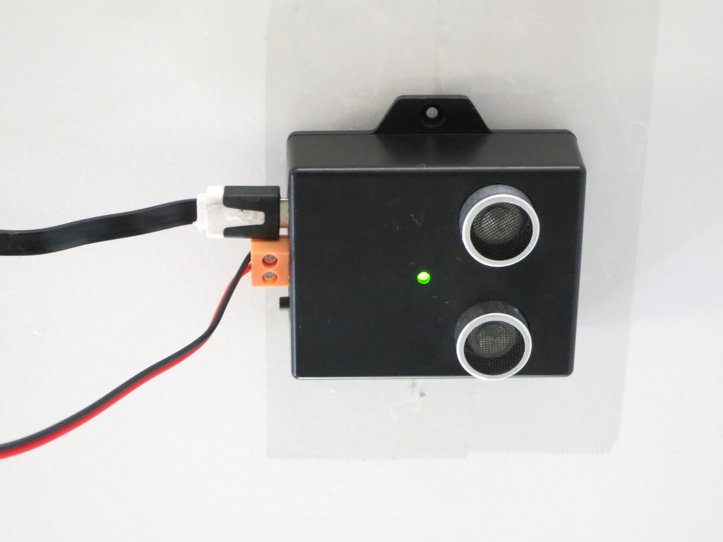
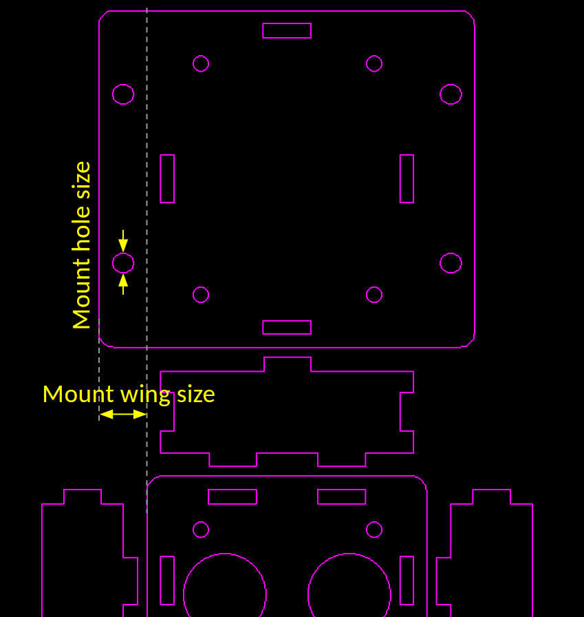
  • Mount wing/hole size: if you need the back panel to be wall-mountable (which is generally the case for my boards),
    you can define the width of the wing and mount hole size (diameter).
  • Round corner r: radius of the rounded corners.
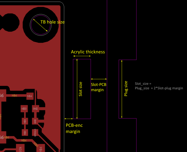
  • Slot-plug margin: this will shrink the plug size slightly to make it easy to insert into the slot. The default is 0.1mm but I suspect leaving it 0 is fine (because laser cut holes generally have negative error, meaning they are larger than design).
  • TB hole size: top-bottom hole size. This is set according to the size of screws/pillars you need. For example, if you plan to use M3 screws, set this to be slightly larger than 3.0; if you plan to use M4 screws, make it slightly larger than 4.0 and so on.
  • Eagle layer: defines which Eagle layer it uses to draw the enclosure. By default it uses layer 104.

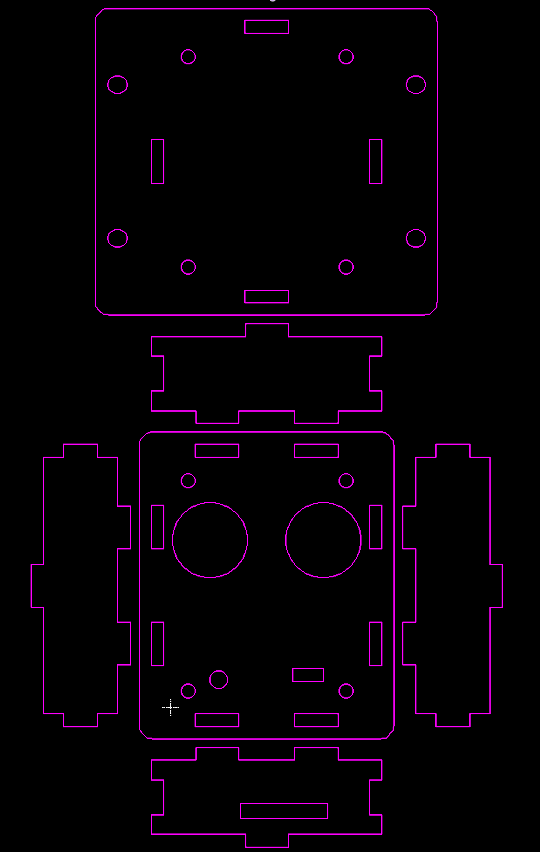
Running the Script: upon running the script, it will hide all layers except the Acrylic layer (104 by default). This allows you to see the overall enclosure design. You can go back and un-hide the other layers. If you re-run the script, it will remove the existing content on the Acrylic layer, and re-create the outlines. So be careful re-running the script — if there is anything you want to preserve (such as custom cutouts as explained below), you want to put them in a different layers so that they don’t get wiped out.

Annotated figures are more intuitive for explaining the parameters:

Creating Custom Cutouts and Text Engravings

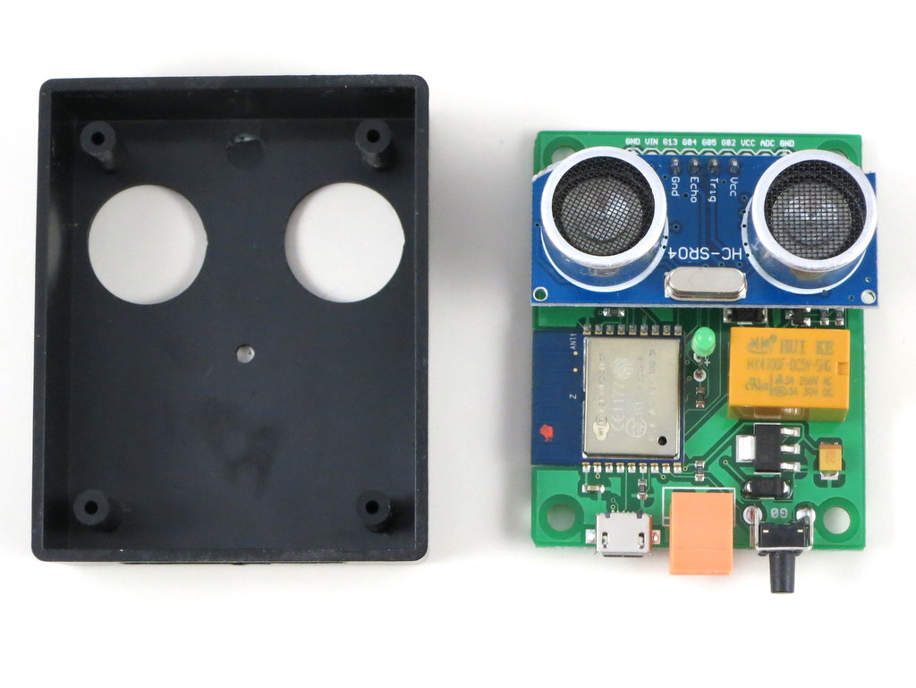
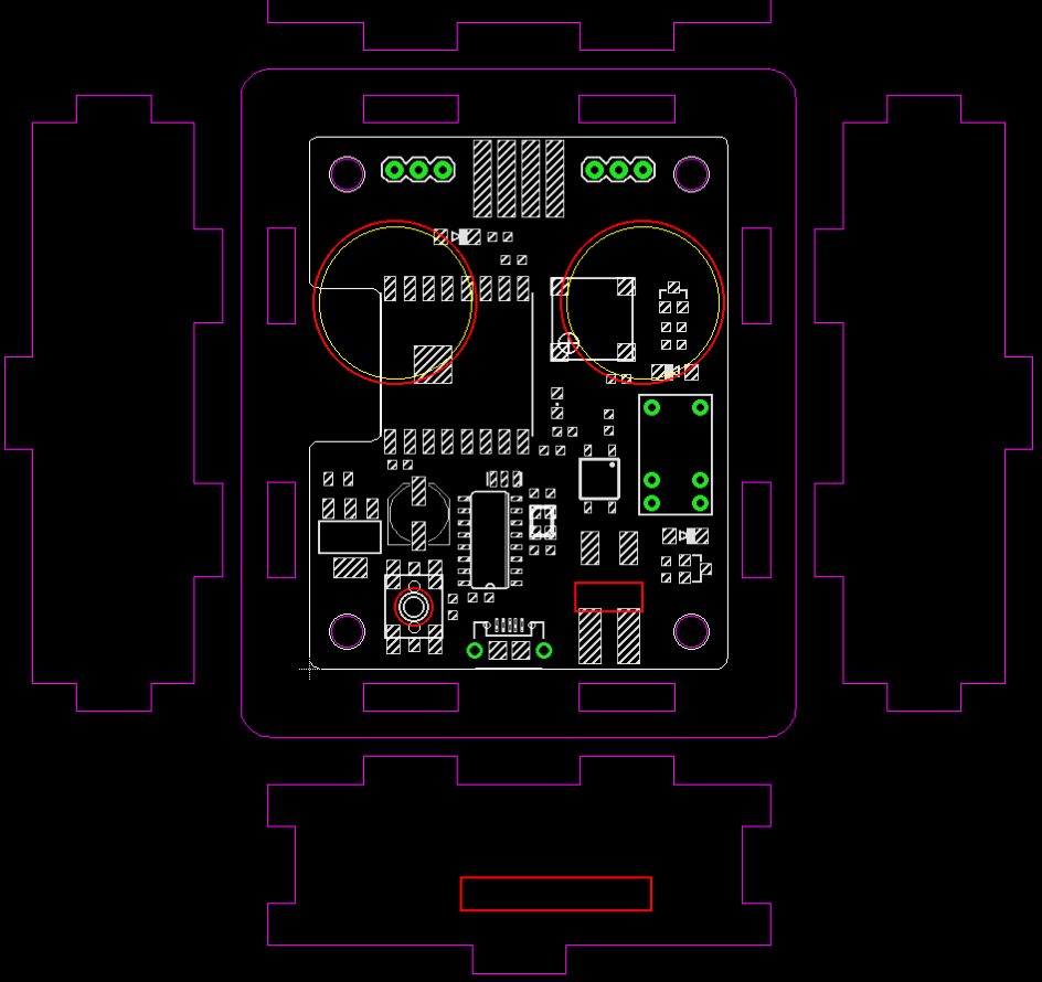
The script doesn’t automatically create cutouts for connectors, and that part you have to do it yourself. Still, having the enclosure outline embedded with the PCB design makes it easy to align the cutouts with the connectors. As shown in the last image above: the custom cutouts (colored in red) are embedded in the PCB design, so you can precisely align each cutout with its designated connector. I generally create the custom cutouts in a different layer, so that in case the Acrylic layer gets wiped out, the cutout layer is still preserved. You can also add text engravings — where I order acrylic pieces, they can add laser engravings for only a small amount of additional cost. So if I need any labels for the connectors, I can easily add them to the custom cutout layer and get them ordered as engravings.

Order Laser-cut Acrylic Pieces

Once the design is finalized, I place an order from a vendor on Taobao.com — the Chinese equivalent of eBay. To prepare the design for ordering, I export the Acrylic layer and Custom Cutout layer together into a DXF file in EagleCAD, then convert it to Adobe Illustrator (.ai) file, and send it to the vendor. I then specify the acrylic thickness, color (the most common is transparent, but there are a variety of other colors to choose from). Make sure the scale of the design is appropriate — Chinese vendors work with millimeter (Americans should too!), so make sure the design is scaled to the correct millimeter scale, which you can do easily in Illustrator.

Assemble the Enclosure

Assembling the enclosure is fairly straightforward: it involves a set of screws on the top panel and bottom panel, and separation pillars below the PCB and above the PCB. I generally like plastic screws and pillars as they are much lighter than iron or copper screws and pillars. The acrylic pieces come with a brown protective sticky paper cover. You can peel the sticky paper cover. If the acrylic material is transparent, you can see through the enclosure to the circuit board, which looks pretty cool. I generally only peel the top panel and keep the protective cover on the other panels, because peeling a lot of paper is tedious, and the brown paper cover gives a wooden appearance, which is not bad. So I keep them as much as possible. To peel the cover, it’s best to use another acrylic piece, or a stiff card of some sort to lift the cover from one corner, then carefully peel and remove the entire cover. Don’t use your nail as it can easily damage your nail. Acrylic is reasonably scratch-resistant, so using another acrylic to help peel it is totally safe.

The GIF below shows the assembly process:

Limitations and Todo for the Future

Perhaps the biggest limitation of laser-cut enclosure is the assembly time — putting all those screws and pillars together cost time and labor. But given that there is no upfront cost, it’s pretty suitable for small-scale projects, or serving as a temporary enclosure until you have a more permanent solution like an injection mold. In addition, for DIY-style projects, you can give the enclosure pieces to the customers and let them assemble the enclosure. It’s actually quite fun, kind of like the philosophy of Ikea furniture — its value is not only in the low cost but getting yourself involved in assembling the product provides a more engaging experience.

There are a couple of improvements I want to make to the script and I will try to work them out in the future. One is the ability to create a local file to store the parameters. At the moment if you want to re-design the enclosure for the same circuit, you have to manually remember what parameters you have used before — the script doesn’t remember the previous parameters because every time you run it, it will load the default parameters. It would be nice for it to store previous parameters for a particular circuit board to a local file, making it easy to modify in the future. Another improvement is providing visual aid to indicate where the PCB is located on the side panels, to make it easier to design cutouts for connectors etc. Right now to create cutouts I still have to do a lot of hand calculations, which can be automated in the future.

That’s it. Feel free to try it out and let me know what you think. If you make modifications to the script and improve its features, please be generous to share your contributions!

Review of NeoDen 4 Pick and Place Machine with Vision System

A few years ago I purchased a NeoDen TM-240A desktop pick and place machine, and wrote two blog posts about it. It was one of the most popular desktop pick and place machines on the market back then, and has served me well for the past three years. It does small boards pretty well, but without a computer vision system, it requires a fair amount of manual placement of fine-pitched components; and it only has a fixed set of 27 feeders, which are not entirely sufficient for me.

Recently NeoDen released a new model called NeoDen 4 — it’s their first desktop model that has built-in computer vision system. The vision-based alignment makes it possible to place fine-pitched components with minimal manual work. It has four pick and place heads, which means if can simultaneously pick up to four components at a time. It can fit a lot more feeders, and can handle a variety of component types, including matrix tray components, and any special components that you can lay out in a 3D printed tray. It has a vibration feeder for components in tube packaging. Although I rarely use tube packaging, one notable exception is the CH340G USB-serial chip, which is used in almost all my products, and so far it only comes in tubes. On top of these exciting new features, the machine I ordered comes with a PCB conveyor belt that can automatically feed PCBs into the system. This is really convenient for starting a pick and place job.

img_20160916_162204img_094454

Well, a picture is worth a thousand words, and a video is worth a thousand pictures! Without further ado, here is my video review of this machine:

So far I am pretty happy with the machine. Pricing-wise, it’s surely more expensive than TM-240A, but not significantly. I paid around 9K in total, including DHL shipping and all the feeders (for TM-240A I paid 5.5K). It’s not all perfect so you’ve got to learn the quirks. For example, I learned that the component height is often quite important — without providing the proper component height, the placing may give you a lot of troubles. Also, for components that need better placement accuracy, reducing the placing speed (say, to 50%) helps a lot to improve the accuracy and reliability.

Overall the machine operation is fairly intuitive, and it works in a predictable manner, much better than some of the comparable products I’ve seen on the market. No matter how powerful the machine is, you can’t afford to spend forever learning how to use it. It took me just two days of looking through the user manual, video tutorials, and doing my own trial and error to learn to successfully produce the first board using this machine. I would say it’s pretty good.

Disclaimer
I am not associated with NeoDen in any way. I am just a standard user. Please do NOT contact me for purchasing or sales questions. Go to their company website (www.neodentech.com) for details.


EagleCAD ULP Script

One difficulty I had initially was how to export a PCB design to a format acceptable by the machine. Without this I would have to manually locate the x-y coordinates of each component using the down-facing camera, which would be a huge pain. The user manual and video tutorial had no descriptions about the format of the spreadsheet. After banging my head on the wall for a while, I found one example spreadsheet somewhere in the flash drive that came with the machine, and that seems to work. Then I went ahead and modified an existing EagleCAD script (designed for TM-240A) to match the example spreadsheet. The script can be downloaded from the link below. Please take a look at the README file as it explains how to use the script.


Introducing OpenGarage: an Open-Source WiFi Garage Door Opener

News and Updates

  • We’ve recently found a technical issue with Blynk’s QR code scan feature that makes the Blynk app not work properly on some iOS devices. The symptom is that the app can receive push notifications but the distance value, read count, and LCD widget are not updating. Please check this forum post for solutions. This seems to only affect iOS devices.
  • OpenGarage User Manual (PDF) is available on Github.
  • OpenGarage Firmware 1.0.4 API document is available on Github.
  • Blynk connection issue: recently Blynk updated their cloud server, causing Blynk app to not be able to communicate with OpenGarage. The solution is to update OpenGarage firmware to 1.0.4.
  • Reboot cycle issue: we’ve found a few reports of ‘reboot cycle’ where the controller continuously reboots. This issue has finally been sorted out. The solution is to reflash the firmware using a microUSB cable.


Today I am very excited to introduce you to OpenGarage — an open-source, universal garage door opener built using the ESP8266 WiFi chip and the Blynk app. I’ve wanted to finish this project for a while, as there have been multiple occasions where I left the house in a hurry and forgot to close my garage door, or locked myself out of the house, or had to let a friend or handyman in while I was away. Having a WiFi-based garage door opener (which I can access remotely using my mobile phone) would be super convenient. Recently as I started learning about ESP8266, I found it to be the perfect platform to help me complete this project.

A quick note: this blog post is temporarily the main landing page of opengarage.io. A more professional-looking site is under construction and should be ready soon. Also, the first production run has been ordered, and they should be ready to ship in 2 weeks of time. If you are interested in OpenGarage, you can place your order at rayshobby.net/cart/og.

Here is a video introduction that gives you a quick walk-through:

Here are some head shots of the OpenGarage controller:

IMG_1068IMG_1069

IMG_1007IMG_1070

I made the prototype version using a 3D printed case, and the final version using an off-the-shelf case with custom cutouts. Two pictures of the circuit board are shown on the right above. With OpenGarage, I can now check my garage door status wherever I am, open or close the door remotely, and check the record of recent events through the log and history graph. The controller supports a built-in web interface with embedded HTMLs, and remote access through the Blynk app. The built-in interface is used for local access and changing configuration/settings, while the Blynk app is used for remote monitoring and control.

Hardware-wise, it’s really simple. It consists of:

  • an ESP8266 (WROOM-2) WiFi chip;
  • an ultrasonic distance sensor (HC-SR04);
  • a relay (for triggering garage door actions);
  • a pushbutton and indicator LED;
  • a microUSB connector and CH340G USB-serial chip.

Mounting. The controller is typically mounted to the ceiling at the garage, with the distance sensor facing down. When the garage door is closed, it reads the distance to the ground, or the top of your car if you’ve parked in the garage. When the door opens and comes up, the sensor reads the distance to the door, which is a much smaller value. So by checking the distance value, it can tell if the door is open or closed. The distance value can also tell you if your car is parked in the garage or not, which is an additional benefit that can be useful at times.

For roll-up garage doors, the ceiling mount would not work. Instead, you can mount it to the side of the door, with the sensor facing the outside. This way the logic is reversed: if the distance reading is small, it means the door is closed, and vice versa.

Interfacing with Garage Door System. OpenGarage uses a relay to simulate door button clicks. For most garage door systems, you can simply connect the two wires from the OpenGarage controller to where you would normally insert your door button wires into. The only exception is the most recent Security+ 2.0 systems, which come with a yellow learn button and antenna. These openers use secure door button codes, but you can still interface with them through a compatible door button.

IMG_1066IMG_1009IMG_1008IMG_1073

Alternatively, you can take apart an existing garage door remote, solder two wires to the button, and connect these two wires to OpenGarage. This way, the relay clicks simulate pressing the button on the remote. As long as you have a remote that works with your garage door system, this approach would always work.


Web Interface and Blynk App. The controller has a built-in web interface with embedded HTMLs, implemented using JQuery Mobile. It’s used for WiFi setup, local access (directly using IP) and changing configurations/settings. The controller also supports remote access through the Blynk app, which is a cloud-based service that’s really easy to use. Before proceeding, it’s recommended that you install the Blynk app, create an account, log in, and scan the OpenGarage app QR code to replicate the project inside Blynk. Then go to the project settings and copy the authorization token (32-digit hex code). This way, immediately after the setup step, you can use Blynk to access OpenGarage.

1_og_ap2_og_home3_og_log4_og_options6_og_blynk_app

Initial Software Setup. OpenGarage is powered by a microUSB cable. At factory default settings, it boots into Access Point (AP) mode, creating an open WiFi network named OG_xxxxxx (where xxxxxx is the last 6 digits of MAC). Use your phone or a computer to connect to this network, and then open a browser and type in 192.168.4.1 to access the AP homepage. You will see a list of nearby WiFi networks scanned by the controller. Select (or manually type in) the ssid, input the password, and paste the Blynk token (if you don’t have it, just leave it empty). Then click on ‘Connect’. The controller will go into AP+STA mode, attempt to connect to your router, and report back its assigned IP address.

Once connected, it will reboot into STA-only mode. At this point, switch your phone back to your home WiFi, and click the redirect button (or manually type in the assigned IP) to access the device homepage.

LED and Button Functions. The LED serves mainly as an indicator: in AP mode, the LED blinks rapidly; and in station mode, the LED blinks briefly when the controller reads the distance sensor, which is once every few seconds (configurable). The button (connected to GPIO0) has the following functions: a short click triggers a relay click; and a long press triggers a factory reset (see below). The button can also be used to enter bootloading mode: if the button is pressed when the controller is powered on, ESP8266 will enter bootloading mode. This is useful if you want to upload a firmware through USB (instead of using OTA update).

Reset to Factory Default. At any point, you can press and hold the pushbutton for 5 seconds or more until the LED stays on, then release the button to reset the controller back to factory default.

Built-in Web Interface. At the homepage you can check the distance readings, door status, and a read count value which increments every few seconds as the controller reads the distance sensor. The read count is basically a ‘heart beat’ that indicates if the controller is communicating with your browser or not. You can trigger a button click or reboot the controller. These actions are protected by a device key, which is by default opendoor.

Click the Options button to open the ‘Edit Options’ page. Most of these are pretty obvious. The one you may need to tweak is the distance threshold, which the controller uses to tell if a door is open or closed. Basically, measure the distance from the sensor to the door (when it’s fully open), and that to your car, and pick a value in between the two. The settings are all saved in a configuration file in the flash memory, so they won’t get lost when the power is down.

At the homepage, click the Log button to open the log page. There you can see the list of recent events. The homepage also shows the current firmware version. Next to the version number is an ‘Update’ button, which allows you to upload a new firmware through the web interface (thanks to the OTA update feature available to ESP8266).

Blynk App. For remote access, the Blynk app is really easy to use. Once you’ve set a token, OpenGarage will communicate with Blynk’s cloud server and report its status. Like the built-in web interface, the app allows you to check distance readings, door status, and trigger a button click. Additionally, it provides a history graph that visualizes previous events, and push notifications when the door opens or closes (note that Blynk limits push notifications to no more than one per minute).


Resources and Technical Details

I’ve published the hardware design files and firmware code in Github. Those who are interested in the technical details can go to:

to find out all the low-level details. These include the circuit schematic and PCB (in EagleCAD format), 3D model of the enclosure, OpenGarage Arduino library, and instructions to compile the firmware. If you are interested in modifying the 3D printable enclosure, go to tinkercad.com, log in, and search for ‘OpenGarage’ and you should find the 3D model I created there.

og1.0enclosure

If you want to extend the functionalities of OpenGarage, there are several spare pins which are mapped out on the PCB for adding additional sensors etc.

Overall it has been a very pleasant experience using ESP8266 for this project. It’s inexpensive, powerful, and has active community support. I can’t think of any reason why not to use it for all my future projects 🙂

If you are interested in buying OpenGarage, you can place your order at rayshobby.net/cart/og.


FAQ

Q: How do I update OpenGarage firmware?
A: Compiled firmwares are all released on
OpenGarage github. For example, here is the direct link to firmware 1.0.4:
https://github.com/OpenGarage/OpenGarage-Firmware/raw/master/Compiled/og_1.0.4.bin
Before proceeding, note that once a new firmware is uploaded, the log will be erased, so keep a copy of the log if you need.

  • Use the web interface to update firmware (click the ‘Update’ button at the bottom of the homepage or Options page).
  • If the built-in web interface is not responding, do a factory reset (i.e. pressing the button for 5 seconds or more), then follow the setup steps but leave the cloud token empty (to avoid any potential Blynk connection issues). Once firmware is updated, go to the Options page and put in the Blynk token, make sure the Accessibility is set to ‘Direct IP + Cloud’.
  • If neither of the above work, you can use a USB cable to flash a new firmware (see instructions below).

After updating firmware, check the bottom of the homepage and make sure the firmware version is correct.


Q: How do I reflash the firmware using a microUSB cable?
A: In the event that the controller cannot boot correctly (such that you can’t have access to over-the-air update), you can reflash the firmware via a microUSB cable.

Step 1: Driver. Depending on your operating system:

Step 2: Bootloading mode and serial port.
Let the device enter bootloading mode. To do so, get a microUSB cable, plug the smaller end to the device’s USB port, then press and hold the pushbutton while plugging the cable’s other end to your computer. The LED light should stay on constantly, and you should not hear any buzzer sound. If not, unplug the USB cable and redo this step.

Next, the device should appear as a serial port and you need to find out the serial port name:

  • Windows: the serial port name is COM? where ? is a number. You can find out the port name in the notification area, or in Device Manager — Serial Port.
  • Mac OSX: the serial port name is /dev/tty.wchusbserial? where ? is a number. You can find out the port name by running ls /dev/tty.wch* in Terminal (i.e. command line).
  • Linux: the serial port name is /dev/ttyUSB? where ? is a number. Run ls /dev/ttyUSB* in command line to find out.

Step 3: Reflash firmware.

Download the OpenGarage reflash package and unzip it. The package includes esptool, nodemcu firmware, and OpenGarage firmware. Open a Terminal (i.e. command line window), cd to the folder where you unzipped the package. Depending on your operating system, run the following command (assuming the device is in bootloading mode):

  • Windows: esptool.exe -cd ck -cb 230400 -cp COM? -ca 0x00000 -cf nodemcu.bin
    where COM? is the serial port name you found in Step 2 above.
  • Mac OSX: ./esptool_mac -cd ck -cb 230400 -cp /dev/tty.wchusbserial? -ca 0x00000 -cf nodemcu.bin
    where wchusbserial? is the serial port name you found in Step 2 above.
  • Linux: sudo ./esptool_lin32 -cd ck -cb 230400 -cp /dev/ttyUSB? -ca 0x00000 -cf nodemcu.bin
    where ttyUSB? is the serial port name. If you use Linux 64-bit, use sudo ./esptool_lin64 instead.

If you encounter any error, check if the device is in bootloading mode. Repeat Step 2 to enter bootloading mode before flashing.

Finally, once the nodemcu firmware is flashed, re-enter bootloading mode (Step 2) and run the above esptool flashing command again, except replacing nodemcu.bin at the end with og_1.0.4.bin. This completes the firmware reflashing.


Raspberry Pi Zero Works with OpenSprinkler Pi

My fortune cookie last night said I have recently left many things undone, and at this rate I may never get them done. Quite alarming indeed. One of the things I haven’t done well recently is regular posting on this blog. So I’ve decided that before the year ends, I have to remedy this by writing a couple of new posts.

The first order of business today is Raspberry Pi Zero. I am sure many of you have heard of it, which is the latest new comer in the Raspberry Pi family, and it has a jaw-dropping price of $5. Five dollars for a tiny computer that runs a full Linux system, how amazing is that! Well, since announced, it’s in such high demand that it went out of stock at most online stores. I’ve been waiting to get my hands on one for a while. A few days ago I was visiting friends in Long Island, New York and discovered that surprisingly I can get the Zero from Micro Center retail stores. So I went and purchased one in their Westbury store. It took me a while to find it in a locked cabinet, and apparently it’s limited to one board per customer. It’s such an anomaly, because normally things in high demand and so difficult to get would be very pricey, but this is only $5!

IMG_3369IMG_3370

The main reason for me to get one is to verify if it works well with OpenSprinkler Pi, as several customers have asked me. The answer is yes, as the video demo below shows. But before you decide to dive in, you should be aware of the hidden costs, which can quickly add up. First, to reduce cost the Zero does not have the 2×20 pin headers pre-soldered, and it doesn’t have a standard size USB connector. This means in order to use it with OpenSprinkler Pi, you need to hand solder the pin headers; and in order to connect it to a USB WiFi dongle, you need a microUSB to USB adapter, which is commonly known as the OTG (USB On-the-Go) adapter. If you are not willing to go through the hassle, you’d be better off staying with Raspberry Pi A+, which is only $20.

Here is a display of three Raspberry Pi’s: version 2 model B, A+, and Zero.
IMG_3371

The OTG adapter I ordered hasn’t arrived yet, so I decided to make one myself. It’s quite easy: just cut the connectors from an existing microUSB cable and USB extension cable (which has a USB A female connector), strip them, solder the four internal wires with matching colors, and use some hot glue and electric tape to fix everything in place. I then burned a new microSD card (with the latest Raspbian image) and installed the OpenSprinkler firmware. Plug it into the OpenSprinkler Pi circuit board, and insert 24VAC power supply: Voilà, it boots up in under a minute and I can start turning on and off sprinkler valves right away. There you go, it’s verified! For those who want to see real actions, check out the Youtube video below.

IMG_3372IMG_3373

Currently the OpenSprinkler Pi circuit board doesn’t have screw holes that match those on the Zero. The consequence is that the Zero won’t have much physical support other than the 2×20 pin header, which is pretty tight and does provide reasonable support. I will have to modify the board design to incorporate the screw holes. I am half hoping that the Raspberry Pi foundation would release a new version of Zero with the pin headers pre-soldered and a standard size USB connector. Not sure if this will ever happen, but we will see!

Last Week in Shenzhen

For the past two weeks I have been traveling in China, and I spent the entire last week in Shenzhen, the city known for electronics supplies, assembly and manufacturing, among many other things. I visited Shenzhen two years ago, and had an wonderful time there. On this trip my main missions are to visit a PCB assembly factory, check out a few pick and place machines (I am considering getting a second pick and place machine), to attend the Shenzhen Maker Faire, and above all, to have great food 🙂

IMG_20150618_113010IMG_20150618_110521

IMG_20150619_090311IMG_20150617_134023IMG_20150617_134229


Wells Electronic Technology Ltd.

Earlier this year I started working with Wells Electronic Technology Ltd. to get OpenSprinkler Pi and Expansion Board manufactured there. Wells is one of the numerous companies in Shenzhen that provides professional PCB manufacturing, assembly, testing, and packaging services. I’ve already done 3 orders with them. On this trip I wanted to pay a visit to check out their facilities in person. As a client, I was treated really well. They picked me up from my hotel, showed me around the factory, treated me lunch, and dropped me back to hotel. It was a very satisfying visit. The factory is divided into three sections. The first section is SMT assembly. They have 7 SMT assembly pipelines, each consisting of a stencil printer, pick and place machine, and reflow oven. Not all pipelines are occupied at all times, and the spare times are often used to accomodate small-size orders like mine.

IMG_20150618_105138IMG_20150618_111050IMG_20150618_110944

There is also an X-Ray machine for examining the soldering quality of BGA chips. Fancy!
IMG_20150618_110902IMG_20150618_110521

The second section of the factory is through-hole soldering. The workers first insert through-hole components into circuit boards, which are then sent to wave soldering machines. The third section is testing and packaging. There are literally no less than a hundred workers, all sitting in front of testing tables with testing instruments. It’s a pretty impressive scene.
IMG_20150618_111707IMG_20150618_111934IMG_20150618_111537

At the end of the visit, I took a few pictures with my hosts Celia and Linna. They are both very friendly and hospitable. I was even given gift boxes of sticky rice dumplings, a traditional Chinese food to be consumed on the Dragon Boat Festival.

IMG_20150618_113028IMG_20150618_113039


Revisiting Pick and Place Machines

About two years ago, I bought my first desktop pick and place machine — Neoden TM-240A. This is a decent quality budget machine that’s well-known in the maker community. It’s pretty easy to use and quite reliable. Although we use professional factories to make the OpenSprinkler line of products, for small circuit boards like SquareWear, ESPToy and RFToy, it’s still much more cost effective to make them ourselves. So it’s important to have a good and reliable pick and place machine in house. The major downside of TM-240A is the lack of a mechanical or vision centering system. This is one of the reasons it’s inexpensive. As we scale up, I am now on the market to shop for a new desktop machine with a automated centering system.

Before I went to Shenzhen, I contacted Felix at the LowPowerLab and got his recommendations for the DDM Novastar LE40V that he purchased recently. It’s a US-made high-quality desktop machine that provide both mechanical centering and vision centering. I even paid a visit to DDM Novastar in Philadelphia to check it out in person. The machine is quite impressive. My main concern is the cost — the total cost with feeders would be about $45K to 50K, which is quite steep. So I decided to wait till my Shenzhen trip to check out a few comparable China-made brands.

The first choice I have in mind is the Borey T15-F30 series. It’s a desktop machine with 4 headers and up to 30 8mm component slots. I had a chance to check out a sample machine at Borey’s Shenzhen office. To be honest, this machine is quite bulky, and given its size the 30-slot limit is a bit disappointing. The sales representative took quite a while to set up an initial demo, which made me concerned about the setup overhead. The machine including feeders would cost about $8K to 10K in total, which is a very decent price even after we factor in the shipping cost.

Borey T15-F30

The second choice is the new generation of Neoden’s pick and place machine. At the moment they are advertising their third-generation (TM-245P) machine. Since I’ve had two years of experience with TM-240A, I consider their machines to be well-built and fairly reliable, and their brand trustable. TM-245P is an upgrade to 240A with lots more component slots, mechanical centering, vibration feeder (suitable for components in tube packaging), and support for IC trays. The overall cost is about $6K to 7K.

TM-245P

During the conversations with their sale representatives, I learned that they will soon release the fourth generation with vision centering. This is a very interesting news that has come right in time. Vision centering is ultimately faster and more accurate than mechanical centering, so I’ve decided to wait for a couple of months for their fourth generation to become available. I’d like to get a sense of how it works before finalizing my decision.


Shenzhen Maker Faire 2015

I intentionally scheduled my trip to overlap with the Shenzhen Maker Faire 2015, which happened over the June 20 weekend. June 20 is also the Dragon Boat Festival, when we happily enjoyed the sticky rice dumplings of all sorts of flavors. The Chinese government has apparently decided to invest heavily in the make culture (a wise move!), and sponsored this event. As a result, it’s free to exhibit, free to attend, and even parking is free on site. The event was well organized with lots of makers. Compared to the Bay Area Maker Faire, it’s somewhat lacking in diversity, in that many exhibitions are of similar nature, and they are almost 100% for-profit companies/start-ups. I miss the days when the Maker Faire consists of mostly small but passionate makers who have the ‘I do it because I can’ spirit, not necessarily having profit-making as the primary focus. Let’s be honest, once it’s driven by profit, the focus is shifted to sales and marketing, and those are the kind of things I am neither good at nor very interested in. In any case, just my wishful thinking for future Maker Faire events.

IMG_20150619_090311IMG_20150619_090328IMG_20150619_093742

IMG_20150619_113659IMG_20150619_141548

Saturday (June 20) evening, I went to a social gathering organized by Hack A Day. Met some new friends and had a great time over there.

IMG_20150620_192148IMG_20150620_200418

So ‘Good Bye, Shenzhen’ for now, but I hope to see you again soon!

mmexport1435211485267

We are at Bay Area Maker Faire 2015

Just a quick update: we are at the Bay Area Maker Faire 2015, station 2, booth 2542 (next to the game of drones). This year Samer is also joining me at the booth, so it’s gonna be great 🙂 We are demonstrating OpenSprinkler, OSPi, OSBo, OSBee Arduino shield, as well as SquareWear, RFToy, ESPToy, AASaver. In addition, we are debutting SquareWear WiFi — the new version of SquareWear powered by ESP8266 WiFi chip. Check out the quick 10 seconds demo below. If you are at the Maker Faire, come to check our our booth!

bamf2015

SquareWear WiFi LED Matrix Demo:

A Batch of New OpenSprinkler 2.3 Manufactured at WAi

Since March this year, orders of OpenSprinkler have been increasing rapidly. Within a couple of weeks, we’ve done two batches of OpenSprinkler 2.3 at our local manufacturer — Worthington Assembly Inc. (WAi). Previously I have blogged about OSPi manufactured at WAi, and I’ve shown videos of their SMT surface mount manufacturing pipeline, including pick and place machine and reflow oven. This time, I was able to get two great videos of the selective soldering machine, which is used for through-hole soldering. Check the video here:

Below are some snapshots. First, before soldering, the boards are queued, and all through-hole components are hand inserted to the board,

IMG_0755IMG_0757

Next, each board goes through a pre-heating machine to get pre-heated, and then sent to the selective soldering machine. The selective soldering includes a fluxing phase, and soldering phase. Check the video above for details.
IMG_0750IMG_0751

This is the result of the selective soldering. Looks very nice, and much better than hand soldering!
IMG_0754

I realize that I haven’t properly announced OpenSprinkler 2.3. So let me give a brief introduction here. OpenSprinkler 2.3 was released ahead of schedule, due to a weird supply chain shortage issue. Basically, OpenSprinkler 2.2 was using Atmel’s ATmega644 microcontroller. A few months ago, as we were about to purchase another batch of 2.2, it suddenly occurred to me that there was a shortage of ATmega644 — our Chinese suppliers said they couldn’t source this component. Then on the US supplier websites, ATmega644 ends up costing slightly more than its next upgrade ATmega1284, which has twice the flash memory size and four times the RAM size! This is very surprising. Even today, you can see that the price of ATmega644 is no less than ATmega1284. Because of this, it no longer makes sense to stick with ATmega644, therefore we decided to immediately upgrade to OpenSprinkler 2.3, by using ATmega1284. This is pretty much the only major change between 2.3 and 2.2. Some other changes include using as much SMT components as possible, to reduce the number of through-hole components.

At the moment, the firmwares for OpenSprinkler 2.3 and 2.2 are pretty much the same. However, since OpenSprinkler 2.3 has doubled the flash memory size and quadrupled RAM size, it’s geared up for major firmware upgrades in the future. At the minimum it will be able to allow for a larger number of stations, more programs, and more data stored in the microcontroller.

So in sum, this was an upgrade that went ahead of schedule, and was due to an unexpected shortage of the previous microcontroller.

Introducing ESPToy 1.2 (with Lua Firmware)

A little while back I released the very first version of ESPToy — a ESP8266 Development Board with a few useful on-board components like color LED, button, and temperature sensor. It has a built-in ATmega644 microcontroller, and pin headers for plugging in a ESP-01 through-hole WiFI module. Shortly after that, I discovered the Lua firmware (named nodemcu) for ESP8266. At first I didn’t pay much attention — Lua is a new language that I’ve never used before, and I wasn’t sure if it’s worth my time learning about it. At the same time I was getting tired of the AT firmware (the original firmware that comes with ESP), partly because it’s not very stable, and partly because it’s complicated to use and involves an extra microcontroller to communicate with it.

Over time I saw increasing development and community support on the Lua firmware. So I became more curious. The final push came recently: there was a supply chain problem of the ATmega644 microcontroller. I was about to purchase a new batch of ESPToy 1.1, but the microcontroller is difficult to source from my suppliers in China. I decided that I should give the Lua firmware a try — if it works, I don’t have to use an extra microcontroller any more!

That’s where I wish I had known it earlier — the Lua firmware is, in my opinion, all around better than the AT firmware. It’s easy to use, especially for writing simple web servers; it’s more stable, and best of all, it runs Lua scripts directly on the ESP module, removing the need to use an extra microcontroller. So here comes ESPToy 1.2, with a surface mount ESP8266 module, pre-flashed with the Lua firmware and a start-up demo (WiFi color LED demo):

Built-in Components. Similar to the previous versions, ESPToy 1.2 has a built-in color LED, pushbutton, mini-USB port and the CH340G USB-serial chip. The pushbutton is internally wired to GPIO0 and can be used to re-flash the firmware if needed. The way Lua firmware works is that you send scripts to it through the serial port. The module will execute the script on the fly, and return results (if any) back to the serial port. This is different from a standard microcontroller program in that the scripts are interpreted (not compiled ahead of time), much like how Javascript, Python, and other scripting languages work. This provides a lot of flexibility, including receiving and running a dynamic script on the fly!

IMG_0716server_example

Pin Definitions. ESPToy 1.2 internally assigns the following pins for the built-in components:

  • Lua pin 2 (hardware GPIO4): Red LED
  • Lua pin 1 (hardware GPIO5): Green LED
  • Lua pin 4 (hardware GPIO2): Blue LED
  • Lua pin 3 (hardware GPIO0): Button (active low)

Note that these pin names refer to the pin indices defined by the Lua firmware. These are different from the hardware GPIO pin numbers.

One big advantage of the Lua firmware is that it runs directly on the ESP microcontroller, removing the need for an extra microcontroller. This simplifies the hardware design and reduces cost. The module comes with 1 analog pin and several digital pins. It can do most things that an Arduino can, such as writing and reading a GPIO pin, reading an analog sensor, PWM, I2C, SPI, UART. But what it really excels is the capability of creating web services and handling WiFi connections. It also has a file system, storing scripts and data directly to the built-in flash memory. This is a huge advantage over Arduino, and it’s pretty much an all-in-one solution to build Internet of Things (IoT) gadgets. Probably the only disadvantages would be the relatively small number of available pins, particularly analog pins, and that the PWM speed is quite low. Other than these, most Arduino applications can be easily adapted to Lua scripts, but now with WiFi capability!

Lua 101. So what’s the catch? Well, learning a new language is a barrier. Lua is similar to C++ and Java, but it’s after all different, and the syntax is quite flexible, so some code may look obscure at first. To begin, the Hello-World example is pretty trivial:

print("Hello ESPToy!")

notice that unlike C++ and Java, there is no semi-colon at the end. Next, we can blink the LED on ESPToy by:

led=2
gpio.mode(led, gpio.OUTPUT)
gpio.write(led, gpio.HIGH)
tmr.delay(1000000)
gpio.write(led, gpio.LOW)

On ESPToy, the red LED is connected to GPIO2, green to GPIO1, and blue to GPIO4. The above lines are very much similar to Arduino code. Note that just like Python and Javascript, you don’t need to define variable types — the variable types are determined dynamically, so it’s quite flexible. Here is an example of a for loop:

led=2
gpio.mode(led, gpio.OUTPUT)
for i=1,10 do
  gpio.write(led, gpio.HIGH)
  tmr.delay(20000)
  gpio.write(led, gpio.LOW)
  tmr.delay(200000)
end

Next is a demo of using interrupt:

led=2
button=3
gpio.mode(led, gpio.OUTPUT)
gpio.write(led, gpio.LOW)
gpio.mode(button, gpio.INT)
function button_cb(level)
  if level==0 then
    gpio.write(led, gpio.HIGH)
  else
    gpio.write(led, gpio.LOW)
  end
end
gpio.trig(button, "both", button_cb)

This sets up an interrupt for GPIO3 (connected to button), which triggers a call back function when the button is clicked. Lua supports anonymous inline function, similar to JQuery. So you can also write the code this way:

gpio.trig(button, "both", function(level)
  if level==0 then
    gpio.write(led, gpio.HIGH)
  else
    gpio.write(led, gpio.LOW)
  end
end)

If anonymous functions are new to you, this can look a bit weird. But you will quickly get used to it, and find it convenient.

WiFi Web Server 101. While the above examples replicate what an Arduino can do, the power of ESP is in its WiFi capability and creating web services. For example, the following code creates a WiFi access point named ESPToy-xx (where xx is the last byte of the MAC address) with password opendoor:

wifi.setmode(wifi.SOFTAP)
cfg={}
cfg.ssid="ESPToy" .. (string.sub(wifi.ap.getmac(), 15,17))
cfg.pwd="opendoor"
wifi.ap.config(cfg)

Similarly you can easily set it to run in client mode and log on to an existing WiFi network.

Next, to create a very simple HTTP server, use the following script:

srv=net.createServer(net.TCP)
srv:listen(80,function(conn)
  conn:on("receive",function(conn, payload)
    print(payload)
    conn:send("Hello, ESPToy!")
  end)
  conn:on("sent",function(conn)
    conn:close()
  end)
end)

It creates a TCP server, listening to port 80. Upon receiving a web request, if sends back a simple webpage and closes the connection. Now log on to the ESPToy-xx WiFi, open a browser and type in 192.168.4.1, you will see the webpage returned by the module. If this was to be done with the AT firmware, you would have to use a microcontroller to send commands to ESP, and the code size can easily triple or quadruple the above script. So it’s a total time saver!

File System. Another advantage of the Lua firmware is that it supports a file system. The ESP-12 SMD module has 512KB flash memory space, enough to store many scripts and data files. If this was to be done on the Arduino, you would have to use a SD card shield or EEPROM shield to provide compatible size of storage. So this is yet another invaluable feature.

Using ESPlorer. To work with ESPToy 1.2, I recommend using the ESPlorer software — a Java-based GUI for easily uploading scripts to the ESP module. It supports sending individual commands, saving scripts to files, running script files, removing files. If a script named init.lua exists on the module, the firmware will automatically execute the script upon booting. This is how the startup demo is set to run.

Re-Flashing Firmware. To upgrade the firmware (to newer Lua versions), or to revert back to the AT firmware, you can use the esptool — a Python-based script. Using ESPToy, press and hold the on-board pushbutton while plugging in a mini-USB cable. This will allow the ESP module to enter bootloading mode. Then run esptool to upload a new firmware.

Resources. You can find additional information and examples projects using the Lua firmware from the following websites:

Also, you may want to check a few tutorials of the Lua programming language to get familiar with it.

Purchase Link. In conclusion, this post is meant to be a crash course of the Lua firmware and the basic usage instructions of ESPToy 1.2. This new version of ESPToy is immediately available at the Rayshobby Shop — it replaces the previous version, and is priced at $16 ($8 cheaper than the previous version!). Give it a try, and have fun!

Modified OpenSprinkler Becomes a Biology Experiment Controller

Around Thanksgiving last year, I received a request from a biology lab professor who commissioned me to modify OpenSprinkler to become a custom fluidics controller. The goal is to achieve web-based, programmable control of fluid selector valves, linear actuators, relays, and air valve, to automate a custom biology experiment. I don’t typically accept contract work, but felt this was a very interesting project, as I’m always keen to see wider applications of OpenSprinkler. Also, this particular project fits well with the existing software design of OpenSprinkler, since the control schedules are somewhat similar to typical sprinkler programs.

It took me a while to understand the design requirement and how various components worked. The main component is the fluid selector valve, which selects a specific type of fluid from several input fluid streams. The valve has a number of control wires which are normally pulled high. To set a specific position, you basically use open-collectors (one for each wire) to pull a subset of the wires to ground. This is pretty easy to achieve using OpenSprinkler — there are 8 stations on the main controller, each station is a open-collector that controls on wire. By activating a subset of stations, it sets the selector valve to a specific position.

IMG_0542IMG_0543

The project also calls for two solid state relays (SSRs) to control 110V pumps. The SSR works with logic level signals, so I used two digital pins to interface with them. Next, there are two 12V linear actuators, and a 12V air valve. Because we don’t want to involve too many different power supplies, we decided to go with a single 12V power supply, which powers the OpenSprinkler, linear actuators and the air valve. OpenSprinkler already has a switching regulator inside that can work with 12V, so that’s not a problem. I then used the built-in relay on OpenSprinkler to switch the air valve. To control the linear actuators, I needed two high-power H-bridges. The way linear actuators work is that they each have two wires — apply positive 12V on the two wires, the actuator will start to extend; reverse the polarity, the actuator will retract. This is similar to how a motor works, and it’s typically done through an H-bridge. Because the linear actuator can draw up to several amps of current, I decided to use a 4-channel relay board (instead of MOSFETs) to implement two H-bridges. So four additional digital pins are used to toggle the 4 relays.

IMG_0544IMG_0547

The right image above shows a CO2 sensor. It is used to conditionally open the air valve at the end of the experiment. The idea is that the air valve will only need to be open if the CO2 level is above a certain threshold. I didn’t have chemicals to generate CO2, but had plenty of soda at home, so it was quite easy to create varkous CO2 levels to help test the sensor 🙂

Then as soon as I started working on the software, I realized that the control schedules are actually not entirely the same as sprinkler programs. Specifically, each schedule contains multiple entries, where each entry indicates the status of every component and the time the status will last. It’s kind of like: upon starting the program, the components should be in status A, B, C; after 15 minutes, they will change to status D, E, F; and so on. So I decided to overhaul the existing OpenSprinkler firmware, and rewrite it with a new program data structure. The end result is that each program contains multiple entries. For each entry, you specify the status (such as on/off) of every component, and the duration (i.e. how long the status lasts). In a sense this can also be used to schedule sprinkler programs, and it’s actually very powerful, because it allows you to set almost arbitrary schedules, including scheduling multiple stations to open at the same time, and scheduling the same station to water multiple times within a program. So maybe once day I will make it an alternative OpenSprinkler firmware.

Anyways, it was a really fun project. I didn’t have very good documentations about the work, but I did shoot a couple of video clips. Check them out below.

The initial demo video:

The final demo video with web interface:

Rayshobby Products at Micro Center

We went to Boston for a concert last night and I swung by the Micro Center store at Cambridge, MA to check out the Rayshobby products that they carry in store.

IMG_0226IMG_0228

They have a pretty large ‘DIY Electronics’ section with all sorts of electronic goodies. This is what I pictured RadioShack should be.

After searching around a few times, I found the AASaver, SquareWear, and OpenSprinkler on one shelf. Very exciting! I do wish they were better organized, because as is, there are hundreds of kits and gadgets spread everywhere like baby toys at a daycare center. Seeing them in store does give me a good idea how to package the products more properly in the future.

IMG_0229IMG_0230

IMG_0232IMG_0233

So if you are interested in OpenSprinkler (DIY kit), AASaver, and SquareWear, and if you have a nearby Micro Center store, go and check them out. They also take online orders. I wonder if RadioShack could have been saved if they had taken the lead in offering a wider variety of DIY electronics products. Alas, it may be too late.