After I released the ESP8266-based OpenGarage, there has been a weird bug that kept bugging me: a small fraction of the controllers (let’s say 1 out of 10) would crash on restart, and that leads to an infinite reboot cycle. Once this happens, it seems there is no way to stop it until you reflash the controller with NodeMCU firmware, and then flash OpenGarage firmware back. It’s completely crazy because first, this issue is hard to reproducing — most controllers would work just fine, but once in a while, one would go nuts; second, upon crashing you can check the stack dump but the information is basically gibberish and does not help debugging at all; third, just reflashing the OpenGarage firmware itself is not sufficient — something seems to have been permanently altered in the flash memory such that you have to flash a completely different firmware (NodeMCU for example) to stop it; finally, even this is not a permanent fix — if you reboot the controller regularly for a few times, this issue will eventually happen again.
For the longest time I thought there is a bug in the OpenGarage firmware code that causes this to happen. But the above symptom defies any standard reasoning and explanation. This has kept bugging me until yesterday, I finally sat down and did a number of reproducible tests that helped me finally figure out the cause. It turns out this has to do partly with the ESP8266 hardware quality and partly software. The short story is that every time ESP8266 restarts, the firmware (more specifically, ESP8266 Arduino library) writes the current WiFi SSID and password to flash memory (along with other flash memory operations such as reading config files); over time this may cause a corruption at some point (possibly due to flash memory quality); once this happens, it will keep crashing on restart, and the only way to stop it is to erase the corrupted region (that’s what reflashing NodeMCU firmware accomplishes).
In fact, this issue has already been reported in the ESP8266 Arduino forum. I wish I had discovered this earlier. The solution is actually quite straightforward: simply add WiFi.persistent(false); right at the beginning of the code, that will stop the library from writing SSID and password to flash memory every time. This is unnecessary anyways since OpenGarage firmware already stores SSID and password in the config file.
This simple trick seems to have magically fixed the annoying bug. To be fair, I believe this bug only happens when you manage WiFi SSID and password separately in a config file stored in flash memory space — if the SSID and password are hardcoded into the firmware the issue wouldn’t happen. In any case, I wrote this blog post to document the issue and fix, and hope this may be useful for others who encounter similar issues with ESP8266.
We’ve recently found a technical issue with Blynk’s QR code scan feature that makes the Blynk app not work properly on some iOS devices. The symptom is that the app can receive push notifications but the distance value, read count, and LCD widget are not updating. Please check this forum post for solutions. This seems to only affect iOS devices.
Blynk connection issue: recently Blynk updated their cloud server, causing Blynk app to not be able to communicate with OpenGarage. The solution is to update OpenGarage firmware to 1.0.4.
Today I am very excited to introduce you to OpenGarage — an open-source, universal garage door opener built using the ESP8266 WiFi chip and the Blynk app. I’ve wanted to finish this project for a while, as there have been multiple occasions where I left the house in a hurry and forgot to close my garage door, or locked myself out of the house, or had to let a friend or handyman in while I was away. Having a WiFi-based garage door opener (which I can access remotely using my mobile phone) would be super convenient. Recently as I started learning about ESP8266, I found it to be the perfect platform to help me complete this project.
A quick note: this blog post is temporarily the main landing page of opengarage.io. A more professional-looking site is under construction and should be ready soon. Also, the first production run has been ordered, and they should be ready to ship in 2 weeks of time. If you are interested in OpenGarage, you can place your order at rayshobby.net/cart/og.
Here is a video introduction that gives you a quick walk-through:
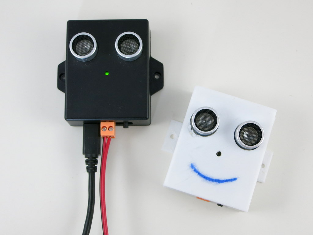
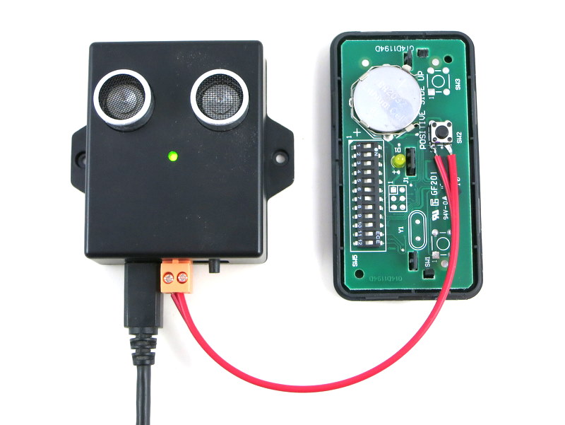
Here are some head shots of the OpenGarage controller:
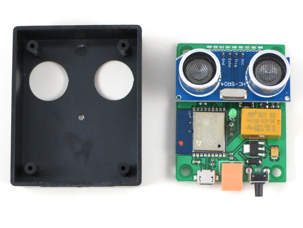
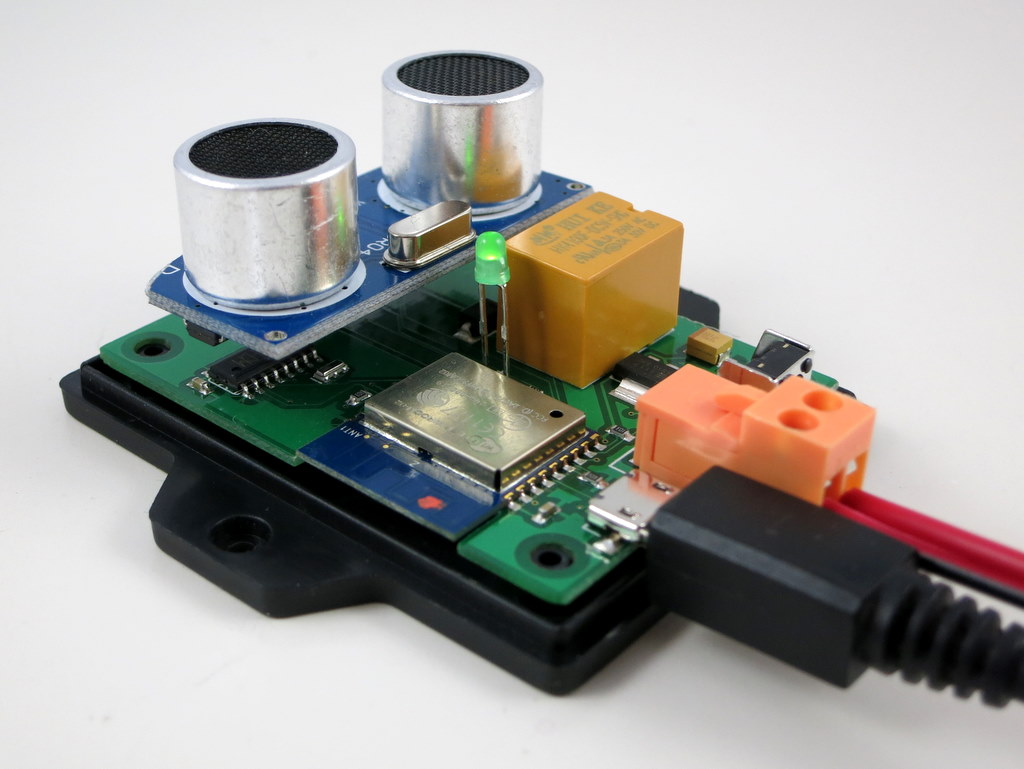
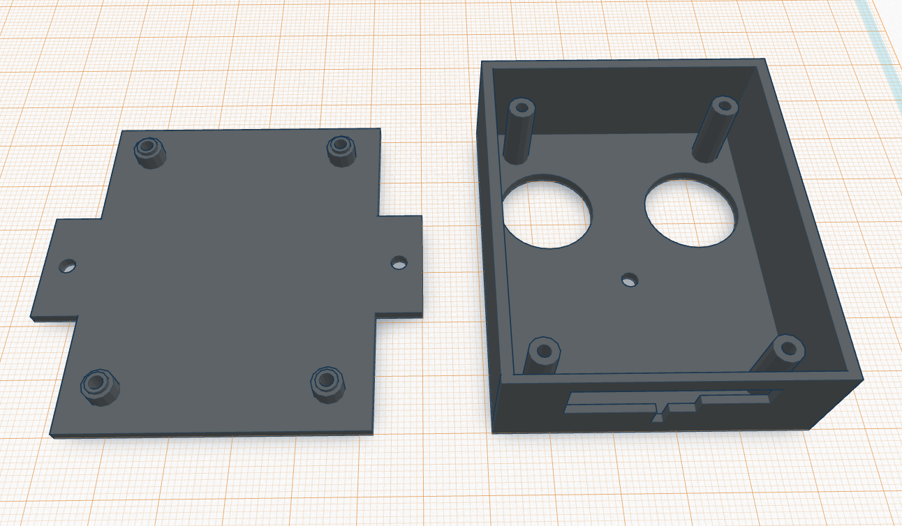
I made the prototype version using a 3D printed case, and the final version using an off-the-shelf case with custom cutouts. Two pictures of the circuit board are shown on the right above. With OpenGarage, I can now check my garage door status wherever I am, open or close the door remotely, and check the record of recent events through the log and history graph. The controller supports a built-in web interface with embedded HTMLs, and remote access through the Blynk app. The built-in interface is used for local access and changing configuration/settings, while the Blynk app is used for remote monitoring and control.
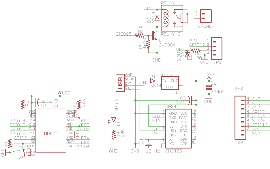
Hardware-wise, it’s really simple. It consists of:
an ESP8266 (WROOM-2) WiFi chip;
an ultrasonic distance sensor (HC-SR04);
a relay (for triggering garage door actions);
a pushbutton and indicator LED;
a microUSB connector and CH340G USB-serial chip.
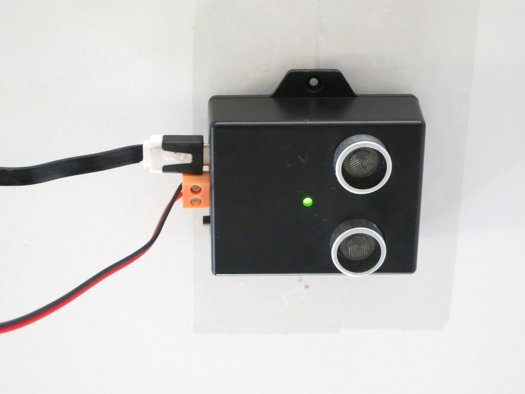
Mounting. The controller is typically mounted to the ceiling at the garage, with the distance sensor facing down. When the garage door is closed, it reads the distance to the ground, or the top of your car if you’ve parked in the garage. When the door opens and comes up, the sensor reads the distance to the door, which is a much smaller value. So by checking the distance value, it can tell if the door is open or closed. The distance value can also tell you if your car is parked in the garage or not, which is an additional benefit that can be useful at times.
For roll-up garage doors, the ceiling mount would not work. Instead, you can mount it to the side of the door, with the sensor facing the outside. This way the logic is reversed: if the distance reading is small, it means the door is closed, and vice versa.
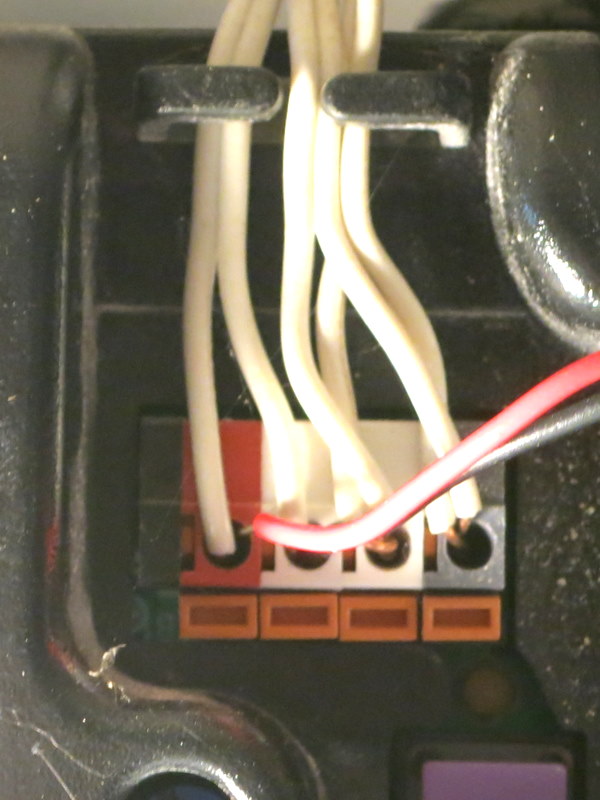
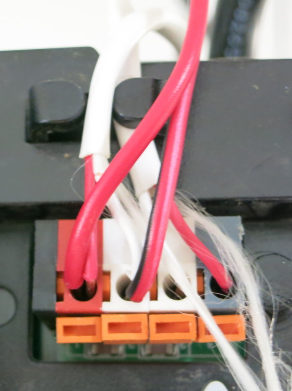
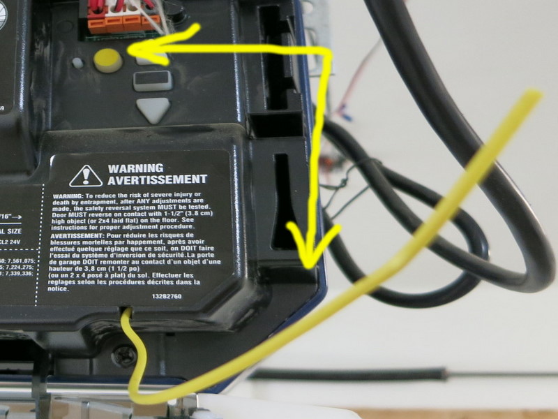
Interfacing with Garage Door System. OpenGarage uses a relay to simulate door button clicks. For most garage door systems, you can simply connect the two wires from the OpenGarage controller to where you would normally insert your door button wires into. The only exception is the most recent Security+ 2.0 systems, which come with a yellow learn button and antenna. These openers use secure door button codes, but you can still interface with them through a compatible door button.
Alternatively, you can take apart an existing garage door remote, solder two wires to the button, and connect these two wires to OpenGarage. This way, the relay clicks simulate pressing the button on the remote. As long as you have a remote that works with your garage door system, this approach would always work.
Web Interface and Blynk App. The controller has a built-in web interface with embedded HTMLs, implemented using JQuery Mobile. It’s used for WiFi setup, local access (directly using IP) and changing configurations/settings. The controller also supports remote access through the Blynk app, which is a cloud-based service that’s really easy to use. Before proceeding, it’s recommended that you install the Blynk app, create an account, log in, and scan the OpenGarage app QR code to replicate the project inside Blynk. Then go to the project settings and copy the authorization token (32-digit hex code). This way, immediately after the setup step, you can use Blynk to access OpenGarage.
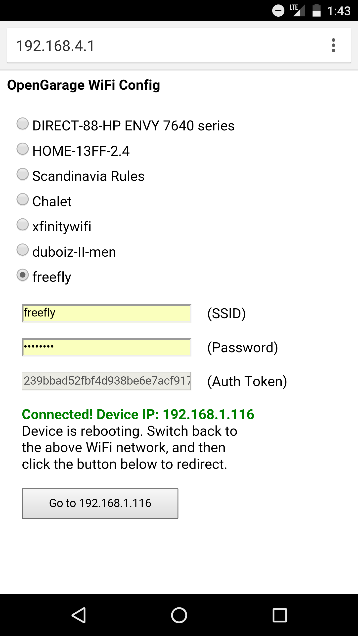
Initial Software Setup. OpenGarage is powered by a microUSB cable. At factory default settings, it boots into Access Point (AP) mode, creating an open WiFi network named OG_xxxxxx (where xxxxxx is the last 6 digits of MAC). Use your phone or a computer to connect to this network, and then open a browser and type in 192.168.4.1 to access the AP homepage. You will see a list of nearby WiFi networks scanned by the controller. Select (or manually type in) the ssid, input the password, and paste the Blynk token (if you don’t have it, just leave it empty). Then click on ‘Connect’. The controller will go into AP+STA mode, attempt to connect to your router, and report back its assigned IP address.
Once connected, it will reboot into STA-only mode. At this point, switch your phone back to your home WiFi, and click the redirect button (or manually type in the assigned IP) to access the device homepage.
LED and Button Functions. The LED serves mainly as an indicator: in AP mode, the LED blinks rapidly; and in station mode, the LED blinks briefly when the controller reads the distance sensor, which is once every few seconds (configurable). The button (connected to GPIO0) has the following functions: a short click triggers a relay click; and a long press triggers a factory reset (see below). The button can also be used to enter bootloading mode: if the button is pressed when the controller is powered on, ESP8266 will enter bootloading mode. This is useful if you want to upload a firmware through USB (instead of using OTA update).
Reset to Factory Default. At any point, you can press and hold the pushbutton for 5 seconds or more until the LED stays on, then release the button to reset the controller back to factory default.
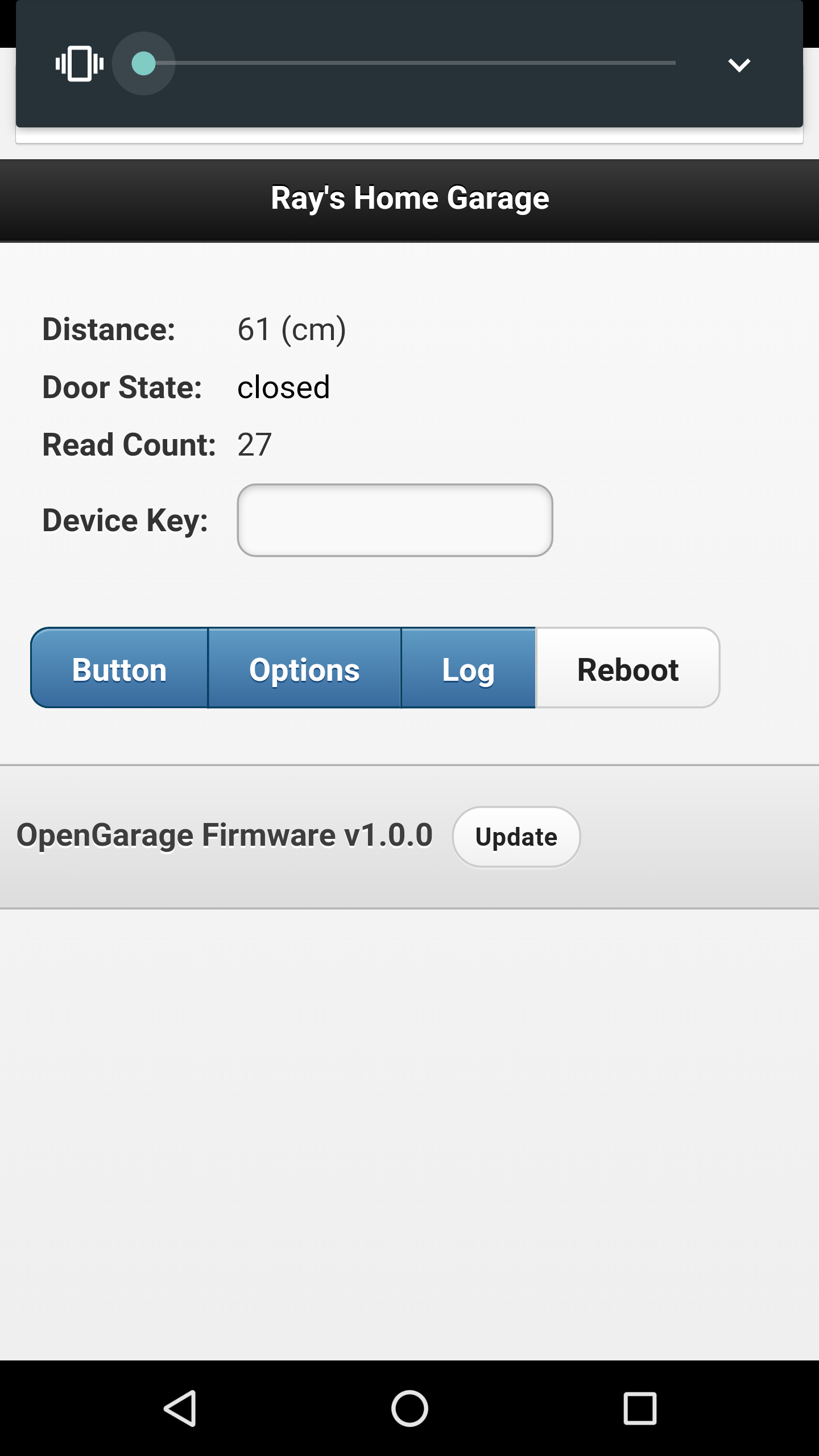
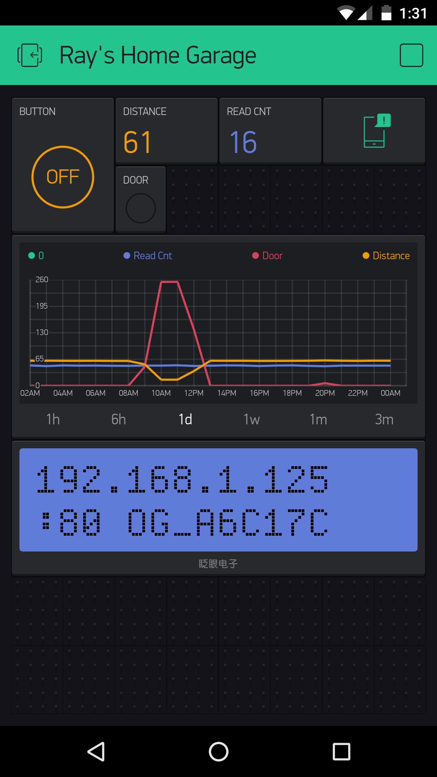
Built-in Web Interface. At the homepage you can check the distance readings, door status, and a read count value which increments every few seconds as the controller reads the distance sensor. The read count is basically a ‘heart beat’ that indicates if the controller is communicating with your browser or not. You can trigger a button click or reboot the controller. These actions are protected by a device key, which is by default opendoor.
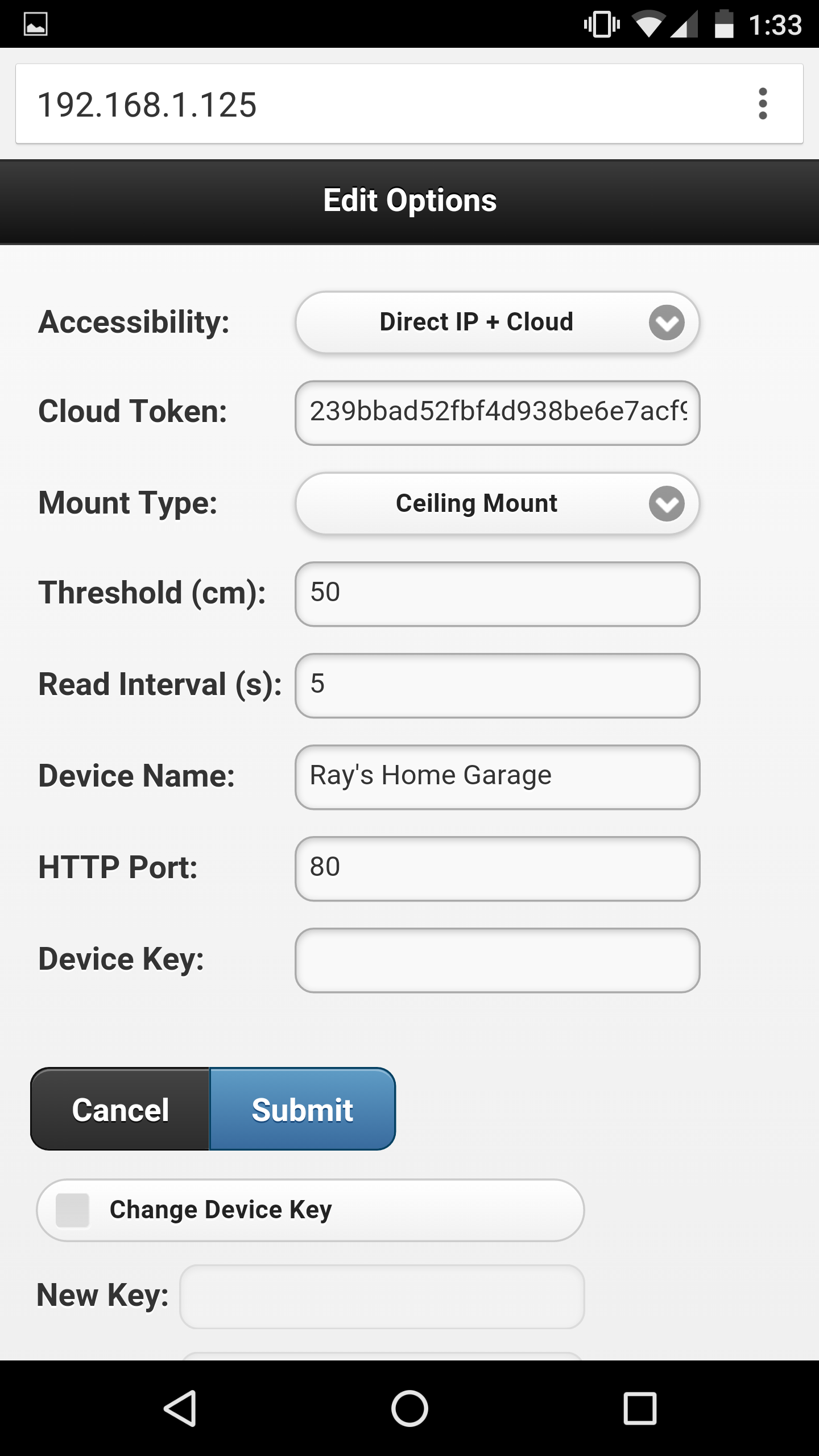
Click the Options button to open the ‘Edit Options’ page. Most of these are pretty obvious. The one you may need to tweak is the distance threshold, which the controller uses to tell if a door is open or closed. Basically, measure the distance from the sensor to the door (when it’s fully open), and that to your car, and pick a value in between the two. The settings are all saved in a configuration file in the flash memory, so they won’t get lost when the power is down.
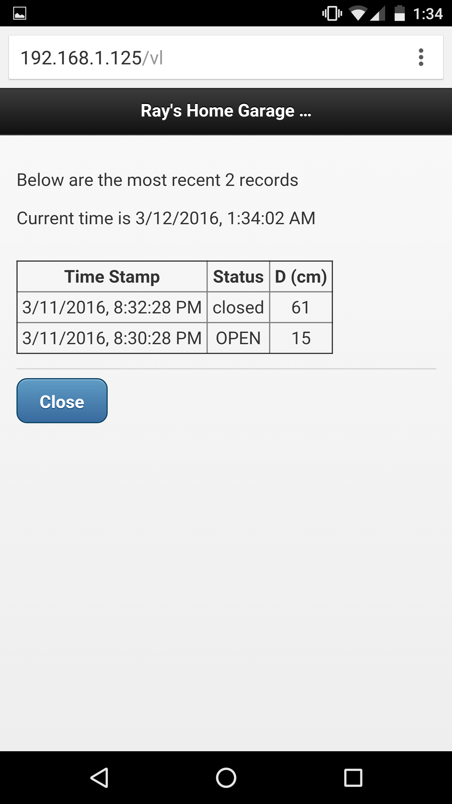
At the homepage, click the Log button to open the log page. There you can see the list of recent events. The homepage also shows the current firmware version. Next to the version number is an ‘Update’ button, which allows you to upload a new firmware through the web interface (thanks to the OTA update feature available to ESP8266).
Blynk App. For remote access, the Blynk app is really easy to use. Once you’ve set a token, OpenGarage will communicate with Blynk’s cloud server and report its status. Like the built-in web interface, the app allows you to check distance readings, door status, and trigger a button click. Additionally, it provides a history graph that visualizes previous events, and push notifications when the door opens or closes (note that Blynk limits push notifications to no more than one per minute).
Resources and Technical Details
I’ve published the hardware design files and firmware code in Github. Those who are interested in the technical details can go to:
to find out all the low-level details. These include the circuit schematic and PCB (in EagleCAD format), 3D model of the enclosure, OpenGarage Arduino library, and instructions to compile the firmware. If you are interested in modifying the 3D printable enclosure, go to tinkercad.com, log in, and search for ‘OpenGarage’ and you should find the 3D model I created there.
If you want to extend the functionalities of OpenGarage, there are several spare pins which are mapped out on the PCB for adding additional sensors etc.
Overall it has been a very pleasant experience using ESP8266 for this project. It’s inexpensive, powerful, and has active community support. I can’t think of any reason why not to use it for all my future projects 🙂
If you are interested in buying OpenGarage, you can place your order at rayshobby.net/cart/og.
Use the web interface to update firmware (click the ‘Update’ button at the bottom of the homepage or Options page).
If the built-in web interface is not responding, do a factory reset (i.e. pressing the button for 5 seconds or more), then follow the setup steps but leave the cloud token empty (to avoid any potential Blynk connection issues). Once firmware is updated, go to the Options page and put in the Blynk token, make sure the Accessibility is set to ‘Direct IP + Cloud’.
If neither of the above work, you can use a USB cable to flash a new firmware (see instructions below).
After updating firmware, check the bottom of the homepage and make sure the firmware version is correct.
Linux: driver is not required, but you need to run all following commands as root or with ‘sudo’.
Step 2: Bootloading mode and serial port.
Let the device enter bootloading mode. To do so, get a microUSB cable, plug the smaller end to the device’s USB port, then press and hold the pushbutton while plugging the cable’s other end to your computer. The LED light should stay on constantly, and you should not hear any buzzer sound. If not, unplug the USB cable and redo this step.
Next, the device should appear as a serial port and you need to find out the serial port name:
Windows: the serial port name is COM? where ? is a number. You can find out the port name in the notification area, or in Device Manager — Serial Port.
Mac OSX: the serial port name is /dev/tty.wchusbserial? where ? is a number. You can find out the port name by running ls /dev/tty.wch* in Terminal (i.e. command line).
Linux: the serial port name is /dev/ttyUSB? where ? is a number. Run ls /dev/ttyUSB* in command line to find out.
Step 3: Reflash firmware.
Download the OpenGarage reflash package and unzip it. The package includes esptool, nodemcu firmware, and OpenGarage firmware. Open a Terminal (i.e. command line window), cd to the folder where you unzipped the package. Depending on your operating system, run the following command (assuming the device is in bootloading mode):
Windows: esptool.exe -cd ck -cb 230400 -cp COM? -ca 0x00000 -cf nodemcu.bin
where COM? is the serial port name you found in Step 2 above.
Mac OSX: ./esptool_mac -cd ck -cb 230400 -cp /dev/tty.wchusbserial? -ca 0x00000 -cf nodemcu.bin
where wchusbserial? is the serial port name you found in Step 2 above.
Linux: sudo ./esptool_lin32 -cd ck -cb 230400 -cp /dev/ttyUSB? -ca 0x00000 -cf nodemcu.bin
where ttyUSB? is the serial port name. If you use Linux 64-bit, use sudo ./esptool_lin64 instead.
If you encounter any error, check if the device is in bootloading mode. Repeat Step 2 to enter bootloading mode before flashing.
Finally, once the nodemcu firmware is flashed, re-enter bootloading mode (Step 2) and run the above esptool flashing command again, except replacing nodemcu.bin at the end with og_1.0.4.bin. This completes the firmware reflashing.
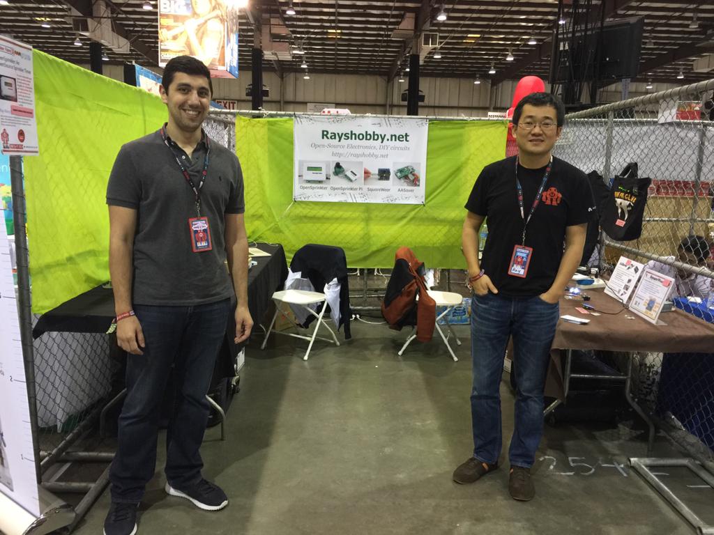
Just a quick update: we are at the Bay Area Maker Faire 2015, station 2, booth 2542 (next to the game of drones). This year Samer is also joining me at the booth, so it’s gonna be great 🙂 We are demonstrating OpenSprinkler, OSPi, OSBo, OSBee Arduino shield, as well as SquareWear, RFToy, ESPToy, AASaver. In addition, we are debutting SquareWear WiFi — the new version of SquareWear powered by ESP8266 WiFi chip. Check out the quick 10 seconds demo below. If you are at the Maker Faire, come to check our our booth!
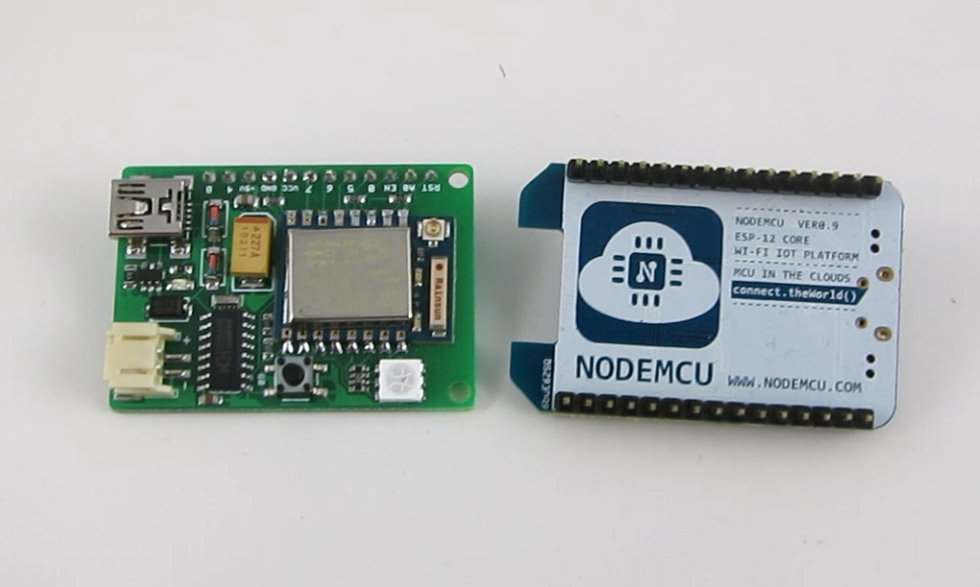
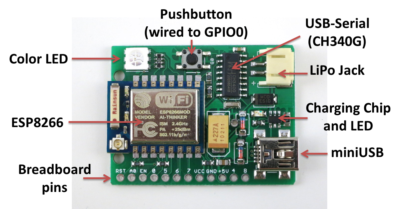
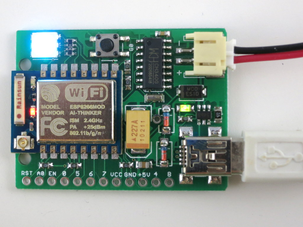
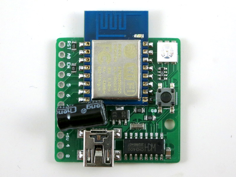
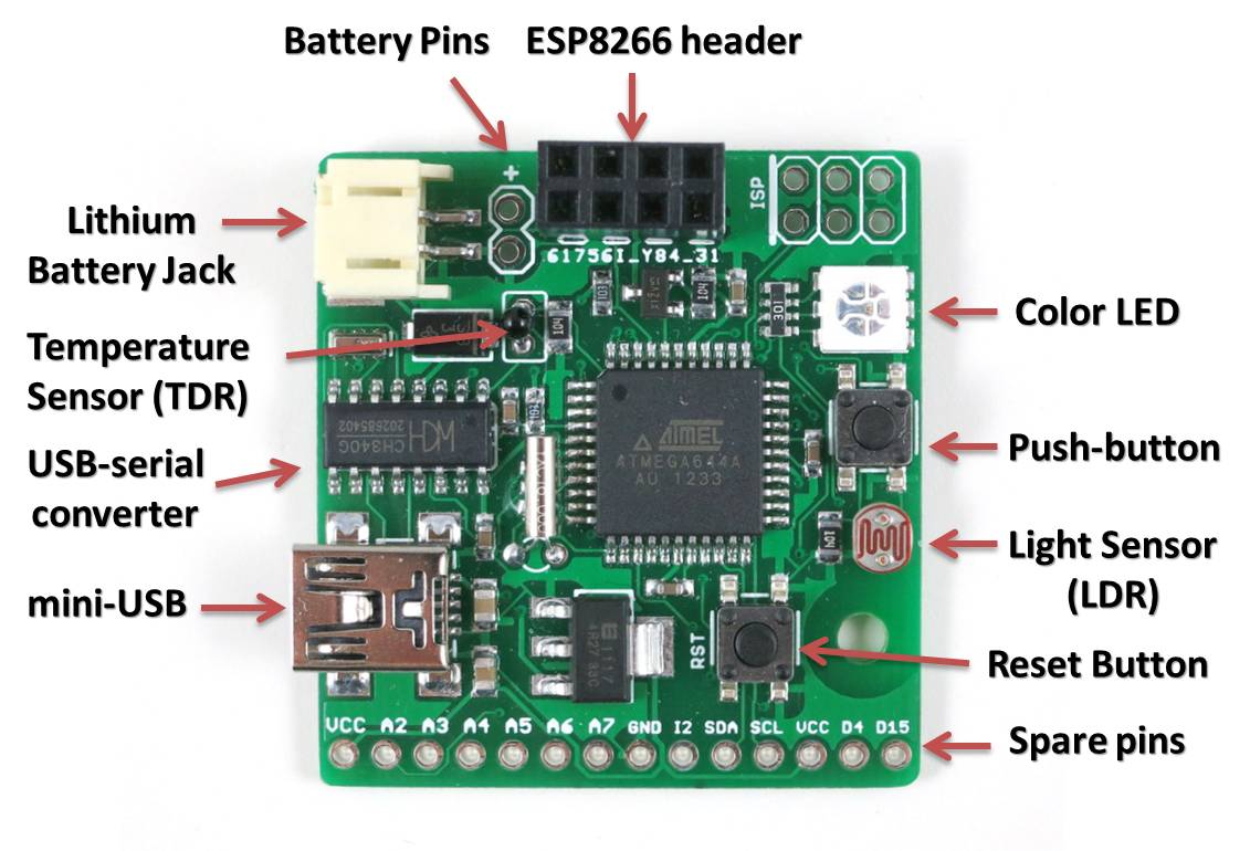
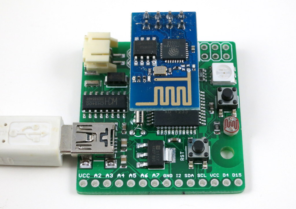
Since the first version of ESPToy, I’ve done some pretty rapid revisions. This post is to introduce the new minor revision 1.21, with LiPo battery jack and charger. As you can see in the annotated diagram below, the main components are the same as ESPToy 1.2: a color (RGB) LED, pushbutton (wired to GPIO0, so it can be used to bootload but also function as a general-purpose pushbutton), a surface mount ESP8266 module, CH340G USB-serial chip, mini-USB port, and breadboard pins. The ESP8266 module is pre-flashed with the latest Lua firmware, and a start-up demo (WiFi-controlled color LED). You can use the pushbutton to re-flash the firmware if necessary. The newly added components are the LiPo battery jack, charging chip (TP4054), and indicator LED.
The LiPo jack and charger are due to popular requests. Since many users want to power the ESPToy with a LiPo battery, and make a standalone gadget, it makes perfect sense to add a LiPo jack. It also make sense to throw in a LiPo charging chip (the same as used on SquareWear and AASaver), to automatically charge the battery whenever a USB cable is plugged in. There is a green indicator LED which will turn off when charging is completed. The charging current is approximately 200mA.
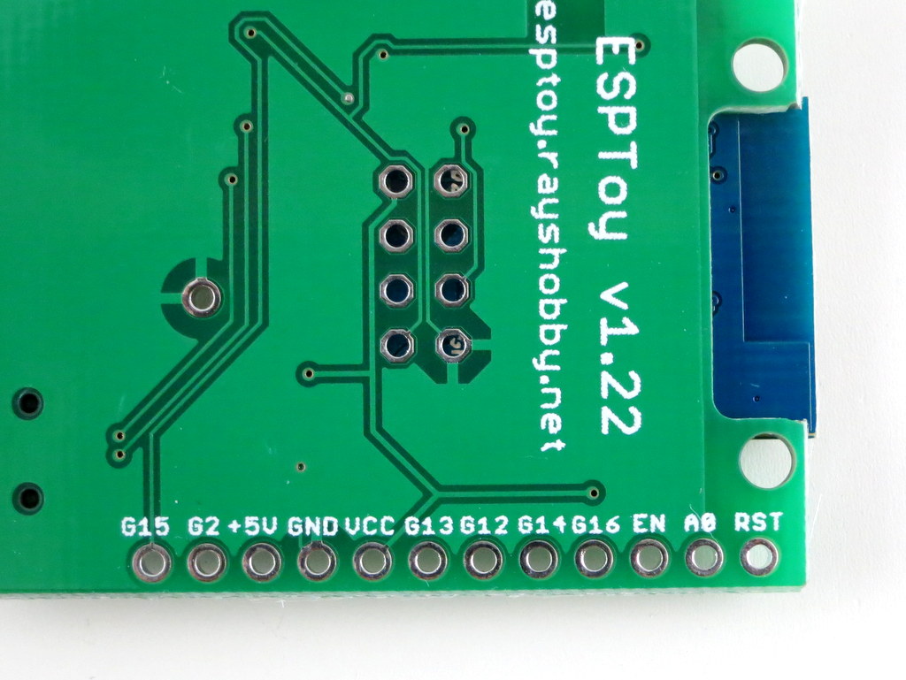
The silkscreen above the breadboard pins marks the pin numbers defined by the Lua firmware. There is one ADC pin (A0) and six general I/O pins (0, 5, 6, 7, 5, 4, 8). In case you want to try a different firmware, and need to know the hardware GPIO pin numbers, just check the silkscreen at the back of the circuit board — those names refer to the hardware GPIO pin numbers. For example, G15 refers to GPIO15. Check the image on the right above.
Another change, as you may have noticed, is that there is no LDO anymore. I got burned by a batch of 3.3V LDOs which aren’t outputting enough current. This lead to some unstable behavior (e.g. ESP8266 restarting etc.). Because ESP8266 can draw a high amount of instantaneous current, the LDO needs to be sufficiently powerful. In this new design, I’ve simply used two diodes to drop the voltage from 5V to about 3.6V (each diode drops 0.7V). In practice, since the USB voltage is often lower than 5V, the VCC is somewhere between 3.2V to 3.6V, which is within the operating voltage of ESP8266. This seems to work quite well, and I’ve not had any power-related issue so far.
I’ve recently used ESPToy at a school workshop. Students really liked it. I was quite concerned with launching 20 WiFi networks in the same room — however, it worked quite well and everyone was able to get the WiFi-controlled color LED demo to work. Given the success of ESPToy, I have been working on redesigning SquareWear as well, to make a special version called SquareWear WiFi, also based on ESP8266. More updates on that will come soon!
A little while back I released the very first version of ESPToy — a ESP8266 Development Board with a few useful on-board components like color LED, button, and temperature sensor. It has a built-in ATmega644 microcontroller, and pin headers for plugging in a ESP-01 through-hole WiFI module. Shortly after that, I discovered the Lua firmware (named nodemcu) for ESP8266. At first I didn’t pay much attention — Lua is a new language that I’ve never used before, and I wasn’t sure if it’s worth my time learning about it. At the same time I was getting tired of the AT firmware (the original firmware that comes with ESP), partly because it’s not very stable, and partly because it’s complicated to use and involves an extra microcontroller to communicate with it.
Over time I saw increasing development and community support on the Lua firmware. So I became more curious. The final push came recently: there was a supply chain problem of the ATmega644 microcontroller. I was about to purchase a new batch of ESPToy 1.1, but the microcontroller is difficult to source from my suppliers in China. I decided that I should give the Lua firmware a try — if it works, I don’t have to use an extra microcontroller any more!
That’s where I wish I had known it earlier — the Lua firmware is, in my opinion, all around better than the AT firmware. It’s easy to use, especially for writing simple web servers; it’s more stable, and best of all, it runs Lua scripts directly on the ESP module, removing the need to use an extra microcontroller. So here comes ESPToy 1.2, with a surface mount ESP8266 module, pre-flashed with the Lua firmware and a start-up demo (WiFi color LED demo):
Built-in Components. Similar to the previous versions, ESPToy 1.2 has a built-in color LED, pushbutton, mini-USB port and the CH340G USB-serial chip. The pushbutton is internally wired to GPIO0 and can be used to re-flash the firmware if needed. The way Lua firmware works is that you send scripts to it through the serial port. The module will execute the script on the fly, and return results (if any) back to the serial port. This is different from a standard microcontroller program in that the scripts are interpreted (not compiled ahead of time), much like how Javascript, Python, and other scripting languages work. This provides a lot of flexibility, including receiving and running a dynamic script on the fly!
Pin Definitions. ESPToy 1.2 internally assigns the following pins for the built-in components:
Lua pin 2 (hardware GPIO4): Red LED
Lua pin 1 (hardware GPIO5): Green LED
Lua pin 4 (hardware GPIO2): Blue LED
Lua pin 3 (hardware GPIO0): Button (active low)
Note that these pin names refer to the pin indices defined by the Lua firmware. These are different from the hardware GPIO pin numbers.
One big advantage of the Lua firmware is that it runs directly on the ESP microcontroller, removing the need for an extra microcontroller. This simplifies the hardware design and reduces cost. The module comes with 1 analog pin and several digital pins. It can do most things that an Arduino can, such as writing and reading a GPIO pin, reading an analog sensor, PWM, I2C, SPI, UART. But what it really excels is the capability of creating web services and handling WiFi connections. It also has a file system, storing scripts and data directly to the built-in flash memory. This is a huge advantage over Arduino, and it’s pretty much an all-in-one solution to build Internet of Things (IoT) gadgets. Probably the only disadvantages would be the relatively small number of available pins, particularly analog pins, and that the PWM speed is quite low. Other than these, most Arduino applications can be easily adapted to Lua scripts, but now with WiFi capability!
Lua 101. So what’s the catch? Well, learning a new language is a barrier. Lua is similar to C++ and Java, but it’s after all different, and the syntax is quite flexible, so some code may look obscure at first. To begin, the Hello-World example is pretty trivial:
print("Hello ESPToy!")
notice that unlike C++ and Java, there is no semi-colon at the end. Next, we can blink the LED on ESPToy by:
On ESPToy, the red LED is connected to GPIO2, green to GPIO1, and blue to GPIO4. The above lines are very much similar to Arduino code. Note that just like Python and Javascript, you don’t need to define variable types — the variable types are determined dynamically, so it’s quite flexible. Here is an example of a for loop:
led=2
gpio.mode(led, gpio.OUTPUT)
for i=1,10 do
  gpio.write(led, gpio.HIGH)
  tmr.delay(20000)
  gpio.write(led, gpio.LOW)
  tmr.delay(200000)
end
Next is a demo of using interrupt:
led=2
button=3
gpio.mode(led, gpio.OUTPUT)
gpio.write(led, gpio.LOW)
gpio.mode(button, gpio.INT)
function button_cb(level)
  if level==0 then
    gpio.write(led, gpio.HIGH)
  else
    gpio.write(led, gpio.LOW)
  end
end
gpio.trig(button, "both", button_cb)
This sets up an interrupt for GPIO3 (connected to button), which triggers a call back function when the button is clicked. Lua supports anonymous inline function, similar to JQuery. So you can also write the code this way:
gpio.trig(button, "both", function(level)
  if level==0 then
    gpio.write(led, gpio.HIGH)
  else
    gpio.write(led, gpio.LOW)
  end
end)
If anonymous functions are new to you, this can look a bit weird. But you will quickly get used to it, and find it convenient.
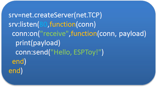
WiFi Web Server 101. While the above examples replicate what an Arduino can do, the power of ESP is in its WiFi capability and creating web services. For example, the following code creates a WiFi access point named ESPToy-xx (where xx is the last byte of the MAC address) with password opendoor:
It creates a TCP server, listening to port 80. Upon receiving a web request, if sends back a simple webpage and closes the connection. Now log on to the ESPToy-xx WiFi, open a browser and type in 192.168.4.1, you will see the webpage returned by the module. If this was to be done with the AT firmware, you would have to use a microcontroller to send commands to ESP, and the code size can easily triple or quadruple the above script. So it’s a total time saver!
File System. Another advantage of the Lua firmware is that it supports a file system. The ESP-12 SMD module has 512KB flash memory space, enough to store many scripts and data files. If this was to be done on the Arduino, you would have to use a SD card shield or EEPROM shield to provide compatible size of storage. So this is yet another invaluable feature.
Using ESPlorer. To work with ESPToy 1.2, I recommend using the ESPlorer software — a Java-based GUI for easily uploading scripts to the ESP module. It supports sending individual commands, saving scripts to files, running script files, removing files. If a script named init.lua exists on the module, the firmware will automatically execute the script upon booting. This is how the startup demo is set to run.
Re-Flashing Firmware. To upgrade the firmware (to newer Lua versions), or to revert back to the AT firmware, you can use the esptool — a Python-based script. Using ESPToy, press and hold the on-board pushbutton while plugging in a mini-USB cable. This will allow the ESP module to enter bootloading mode. Then run esptool to upload a new firmware.
Resources. You can find additional information and examples projects using the Lua firmware from the following websites:
Also, you may want to check a few tutorials of the Lua programming language to get familiar with it.
Purchase Link. In conclusion, this post is meant to be a crash course of the Lua firmware and the basic usage instructions of ESPToy 1.2. This new version of ESPToy is immediately available at the Rayshobby Shop — it replaces the previous version, and is priced at $16 ($8 cheaper than the previous version!). Give it a try, and have fun!
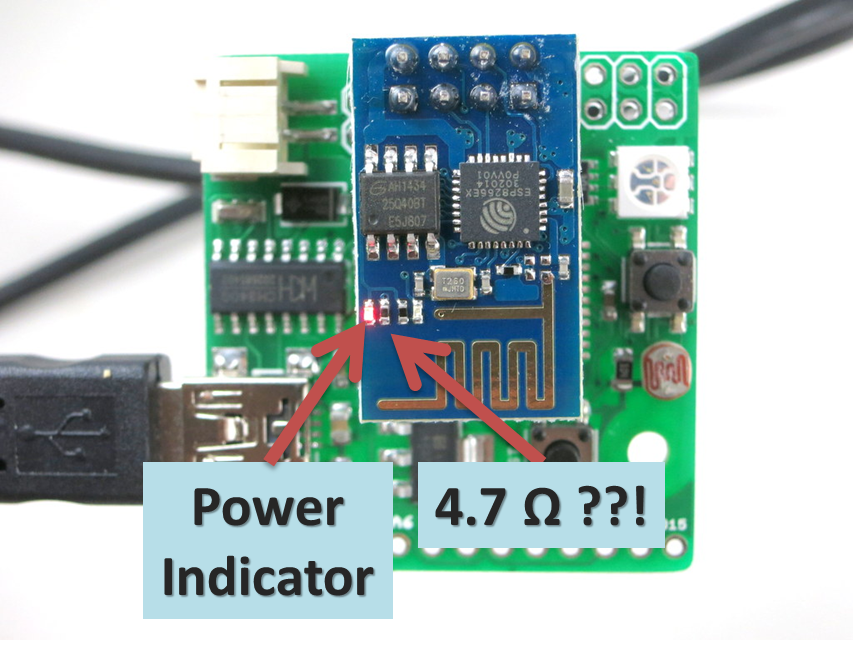
While playing with my ESPToy today, I discovered a rather bizarre issue. The symptom is that some ESP8266 (the ESP-01 version) modules became very hot to touch. In fact, a couple of them started smoking, and the red indicator LED started burning away! Shocking. What’s even more shocking is that these modules continue to function, as if the chip isn’t bothered by the magic smoke at all…
Not all of them have this mysterious problem. So what the heck is going on here? After some digging, I found that on the problematic ones, the tiny resistor next to the red power LED measures only 4.7 ohm?! This can’t be right. This resistor is a clearly a current limiting resistor for the LED — the LED and the resistor are connected in series between VCC and GND. A 4.7 ohm resistor means the current flowing through the LED would be somewhere around (3.3V – 2.1V) / 4.7 ohm = 255 mA! (2.1V is the typical forward drop voltage of red LED). No wonder why the LED (or resistor, or both) is smoking! Phew, that really scared me. To double check, I also measured this resistor on the good ones — they all measure 4.7 kilo-ohm. That’s about right. So clearly the manufacturer has made a mistake and this is really unfortunate. I’ve shot a video of the smoking ESP8266. See below.
Anyway, because some of these defective modules are shipped with the ESPToy, if you’ve bought ESPToy the past few days, you may end up getting some of these units. I sincerely apologize for this. It’s not anything I’ve anticipated. There are several options to solve the issue:
Option 1: let it burn (~~~). Once the LED is burned out and the magic smoke is gone, it will become open circuit and the problem is gone!
Option 2: if it’s scary to look at the magic smoke, or if the LED refuses to burn out, you can use a hot air gun or a soldering iron to remove either the red LED or the resistor next to it, or both.
Option 3: if neither option is ideal, send an email to [email protected] and we can arrange to send you replacements.
Well, this is just one of those headaches to deal with when buying goods from China. To be fair, we buy only from reputable sellers, even so, issues can happen, but we do gain more experience each time a lesson is learned 🙂
ESP8266 — a very low-cost and flexible Serial-to-WiFi module that has gained a lot of popularity recently. It allows any microcontroller to have WiFi capability by simply using serial communication. In a previous blog post, I demonstrated how to use ESP8266 combined with an Arduino to set up a very simple web server. This time I built a standalone gadget for prototyping called the ESP8266 Toy (or ESPToy for short). There is also a more serious web server demo in the end that shows how to serve HTML files from a SD card, and using JSON and AJAX to implement prettier web design.
You should also know that there has been a lot of on-going development for this module. For example, there is a Lua-based firmware for ESP8266, which is quite amazing. Also check out the community forum here.
ESP-12 SMD WiFi module, pre-flashed with Lua firmware and a startup demo script.
3.3V 250mA linear regulator.
Programming using the on-board mini-USB port.
One color (RGB) LED, one pushbutton (used as a general-purpose pushbutton as well as for re-flashing firmware)
Additional pin headers for connecting external components and/or breadboard experiments.
Original ESPToy v1.0/1.1 (retired)
ATmega644 @ 3.3V, 16MHz, with CH340G USB-serial converter and Arduino bootloader.
3.3V 500mA linear regulator.
Programming in Arduino using the on-board mini-USB port.
One color (RGB) LED, one pushbutton, one reset button. (New on version 1.1: one additional button on ESP8266’s GPIO0 pin, useful for firmware upgrade)
One light sensor (LDR), one temperature sensor (TDR).
One 2×4 pin header to fit ESP8266.
Additional pin headers for connecting external components and/or breadboard experiments.
In essence, the ESPToy 1.0/1.1 is a 16MHz Arduino with some handy built-in components for easy prototyping with the ESP8266 WiFi module. Once programmed, the whole assembly can run on battery. There is also a power MOSFET on board to programmably control the power supplied to ESP. This allows you to cut off power to save battery life.
The reason I picked ATmega644 (instead of ATmega328) is that 644 has two hardware Serial interfaces. I am using one for the bootloader and USB communication, the other dedicated for WiFi. This is quite handy and allows you to use the fast baud rates. Also, 644 has twice as much memory as 328, so it’s suitable for building more complex projects.
Demos
As shown in the video above, I’ve written a few examples to demonstrate the basic features of the ESPToy:
To upload the demo Lua scripts to ESPToy 1.2, download and run the ESPlorer software. The Serial port baud rate is 9600 (default). You can open a demo script, click on ‘Save to ESP’ to save the script as a file to ESP’s internal flash memory space. The script will run right away after uploading. You can also click on ‘doFile’ to re-run the script.
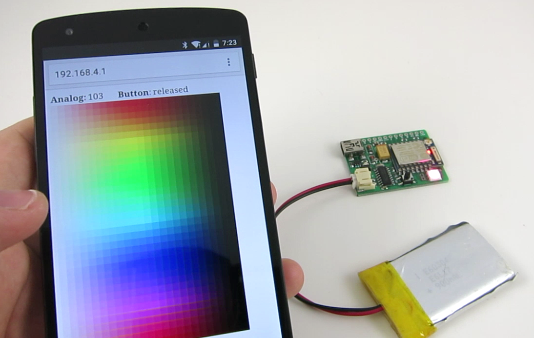
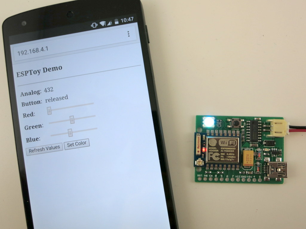
Start-up Demo: every ESPToy 1.2 is pre-flashed with a start-up demo. Plug in a mini-USB cable, the blue LED will blink and the WiFi module will start in access point mode, creating a WiFi network with SSID ESPToy-xx. The password is opendoor. Connect to this WiFi network, open a browser, and type in http://192.168.4.1. Use the sliders to change the LED color, and click on ‘Refresh Value’ to read button status and analog pin value.
Hello ESPToy!: shows the Serial print function.
Blink LED: shows digital pin write, and delay functions.
Button Interrupt: shows how to set up interrupt on a digital pin.
Hello ESPToy Server: shows a simple HTTP web server.
Original ESPToy v1.0/1.1 (retired)
SearchBaud: this comes handy if you forgot the correct baud rate of your ESP8266. It loops through the common baud rates, sends an empty AT command, the detects the correct baud rate by checking the result.
SerialCommand: this demo allows you to send AT commands to ESP8266 through a Serial monitor. Use this demo to experiment with all the AT commands available for ESP8266.
ScanNetwork: this demo starts the ESP8266 in AP mode, which creates a local WiFi network (the name is ESPxxxx). Use a smart phone or laptop to log onto this network, then open a browser and type in IP adddress 192.168.4.1. You will see a webpage with a list of detected WiFi networks. Type in the ssid and password of the target network, then click on Connect. The page will redirect in about 10 seconds to show the client IP address of the module on the target network. This is pretty standard approach to get your WiFi-enabled gadget to log on to your target network.
WebServer: this is a simple web server demo. It serves a html webpage and uses JSON and AJAX to periodically display the analog pin values. The first two analog pins correspond to the light and temperature sensors respectively, so these two values will respond to light and temperature changes. There are also three sliders to set the color of the on-board LED. As I said before, the demo can run on battery, so this can be used as a WiFi-enabled color LED light. Thinking about a simplified version of the Philips Hue? Yup, this is a poor man’s version of that 🙂
WebServer_SD: same as above, except this requires an external SD card slot, so that it can serve bigger and multiple html pages from files stored on the SD card.
Preparation
The ESPToy’s source code is available on Github. Check the README file therein to get started.
Serial Port and Driver:
ESPToy uses a CH340G USB-to-Serial converter. For:
Windows 7, 8, 8.1 and Linux: no driver installation is needed.
On Windows, the Serial Port name is COM? where ? is a number assigned to the USB-serial chip. On Linux, the Serial Port name is /dev/ttyUSB? where ? is a number. On Mac, the Serial Port name is tty.wchxxx.
Programming ESPToy 1.0/1.1 (retired)
Programming the ESPToy can be done through the Arduino IDE (tested with Arduino version 1.0.6). Because ATmega644 is not a board that appears in the stock Arduino, you will need to copy the atmega644 subfolder (from the hardware folder) to the corresponding hardware folder in your Arduino’s installation directory; same with the ESPToy subfolder (from the libraries folder).
Next, launch the Arduino IDE, select Tools->Board->ESPToy, and the correct Serial port from Tools->Serial Port (see below), then select a program from File->Examples->ESPToy, and finally click on Upload
Power Options:
ESPToy can be powered by USB or an external battery. There is a battery jack that fits a standard 3.7V lithium battery. In addition, there are two battery pins (next to the battery jack) — you can solder wires to connect a 3V AA/AAA battery pack. Note that the external AA/AAA battery should not exceed 3.6V (because it’s not regulated).
Flashing a New Firmware to ESP8266
Programming ESPtoy with Arduino: I strongly recommend you to learn to use Arduino to program ESPtoy, due to its flexibility and memory efficiency. While Lua firmware is easy for beginners, to write advanced programs, it’s much easer to use Arduino. Check the resources in this forum post.
On ESPToy 1.2 and 1.1: there is a pushbutton button (on version 1.1 it’s at the upper-left corner) — it’s connected to ESP8266’s hardware GPIO0 pin. If this button is pressed when powering up ESPToy, the ESP8266 will enter bootloading mode waiting for a new firmware. I recommend using the esptool python program to upload firmware, which is very easy to use. Specifically, in command line, run ./esptool.py write_flash 0x00000 xxxx.bin where xxxx.bin is the firmware name.
On ESPToy 1.1, use the SerialCommand sketch to prepare ESPToy as a serial relay.
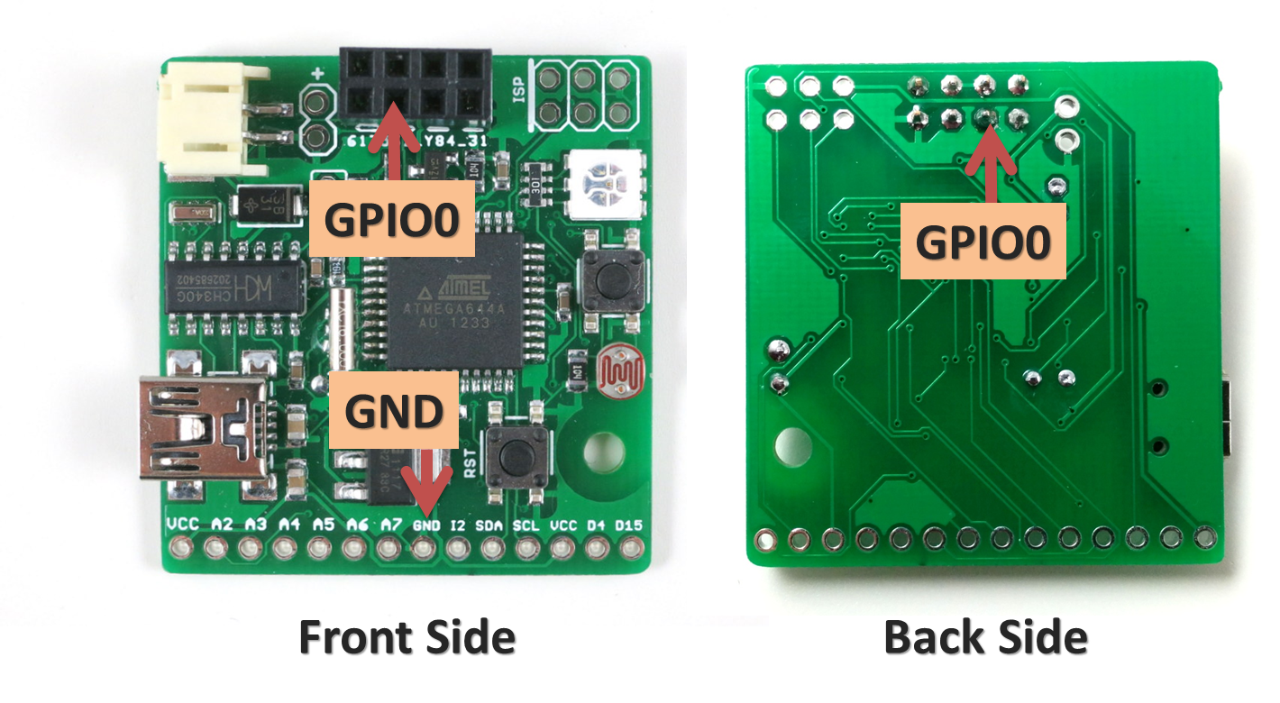
For ESPToy 1.0 (retired): to let ESP8266 enter bootloader, you need to solder a wire from ESP8266’s GPIO0 pin to ground. Specifically, if GPIO0 is pulled to ground, upon power-up ESP8266 will enter bootloader mode waiting for a new firmware from the Serial interface. In contrast, if GPIO0 is pulled up (to VCC), ESP8266 will boot into normal operation mode.
The picture below shows where the GPIO0 pin and a ground pin (any ground pin on the board should work). The wire should be soldered at the back of the circuit board. You can also connect a switch in series on the wire to easily switch between bootloader mode and normal mode.
Once this is done, you can flash the SerialCommand sketch to ESPToy, which will make it serve as a Serial relay. I recommend using the esptool python program to upload firmware, which is very easy to use. Specifically, in command line, run ./esptool.py write_flash 0x00000 xxxx.bin where xxxx.bin is the firmware name.