Post-Maker Faire Update

The trip to Maker Faire Bay Area this year was a great success. This is the first time that I participated Maker Faire as a commercial maker. The two-day event was completely overwhelming to us. I was basically talking to people non-stop: showing demos, explaining technical details, outlining future plans, answering questions, and of course also accepting payments and handing out kits. It was a wonderful experience. I am really glad to have made new friends, many of them gave me generous comments, feedback, and encouragements. That’s the most fun part of the Maker Faire — connecting to people and discovering new ideas. Perhaps the only thing I felt sad about is not being able to go around and check other makers’ exhibits. We were so occupied at our own booth that I barely had any time to even get water. So tips for next time: bring a lot of water, and food too 🙂


(Above: picture at the Maker Happy Hour.)

So what’s happening with OpenSprinkler since Maker Faire? Well, first of all, fulfilling orders and responding to questions have taken a lot of my time. Then, I am really trying to focus and get some time to finish the new interval scheduling program, which I see as the most flexible program that can accommodate many different scheduling need. What has been bugging me is the issue that the newly added features require a lot of program memory space, and the small 32KB flash size of ATMEGA328 doesn’t leave me much to spare. Particularly, the webpages and javascripts are currently all stored in program memory space, and I’ve been playing around to find a way to offload them to somewhere else, such as the external EEPROM. Today, a solution finally came into my mind. While searching for ‘client side include’ (CSI), I realized that it is pretty simple to include, in an html file, a javascript that is stored on a remote server. For example, using:

< script src="http://rayshobby.net/javascripts/ps1.js >< /script >

allows me to include a large javascript file that exists on a remote server and thus does not have to be stored in the microcontroller’s program space. When you access a page on OpenSprinkler, the client (i.e. your browser) will retrieve the webpage automatically upon reading that line. Ah ha, a darn simple way to offload big java scripts from the microcontroller. Why didn’t I think about it before!

Of course the problem with this approach is that if the remote server is down, you can’t really do much. The probability of this happening is usually extremely small. But still, it is a good idea to put webpages related to the most essential functions on-board, while using the remotely stored javascripts for beautifying webpages etc. In any case, this provides a good way to make the precious program memory space available for adding new features.

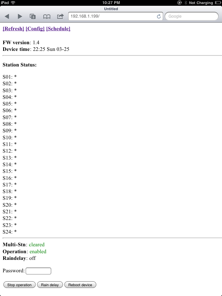
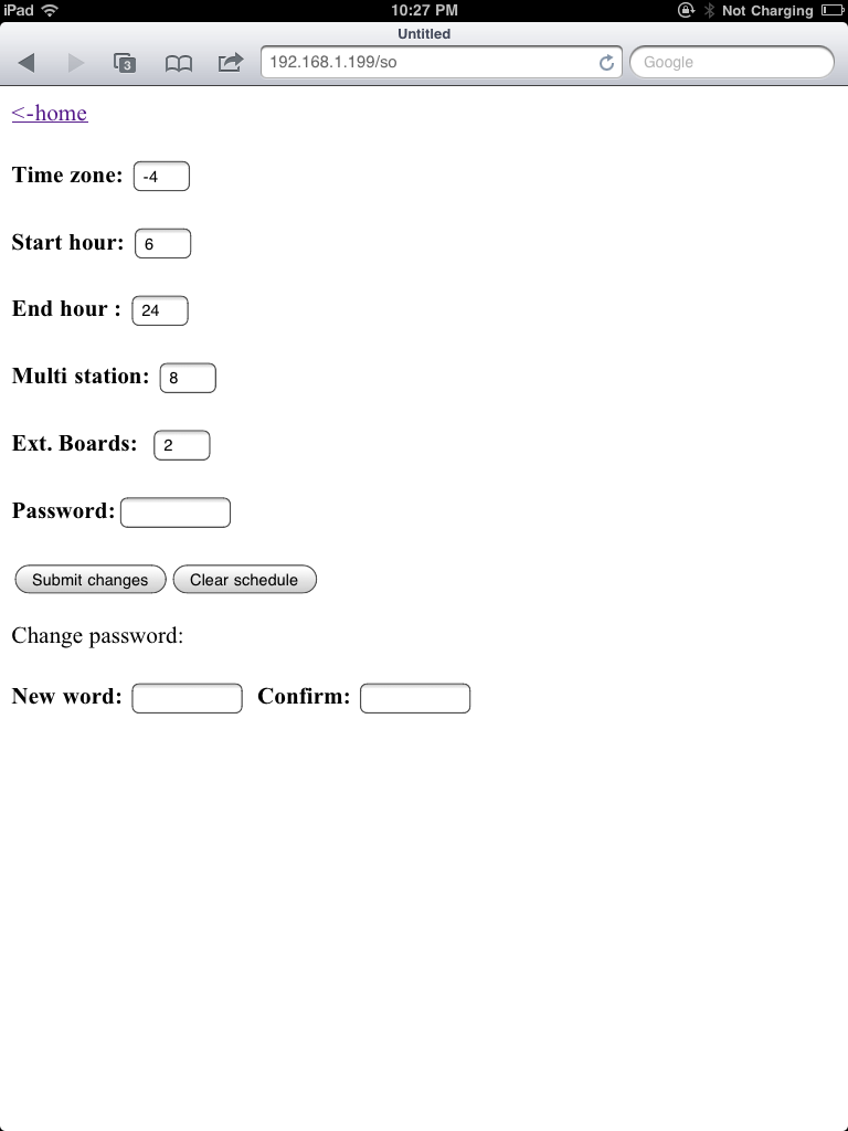
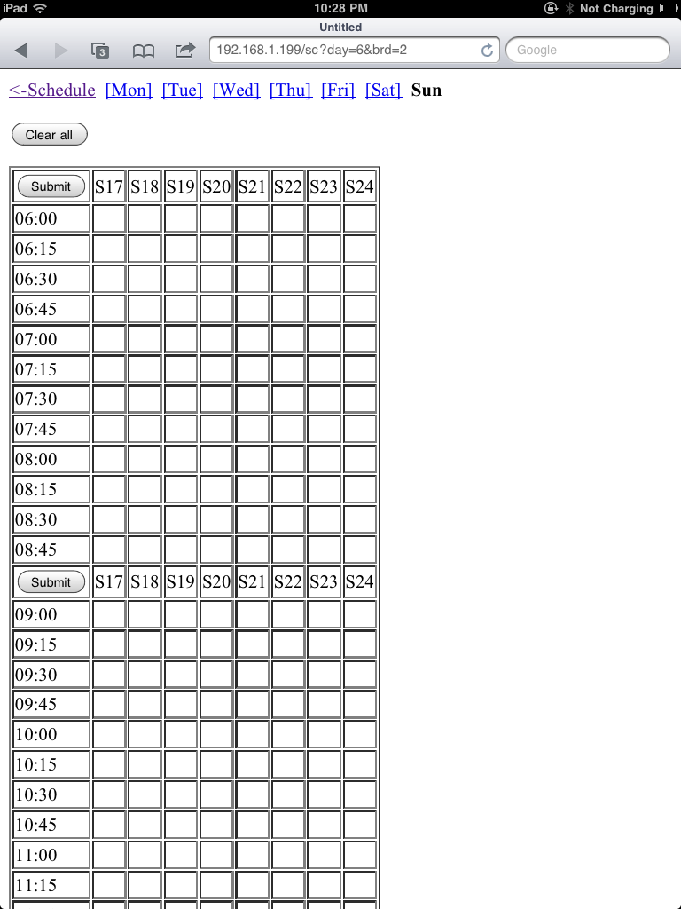
Just to give you an idea of what’s happening, here are two snapshots of the new schedule webpages I am working on:
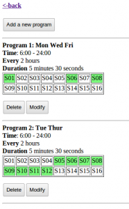
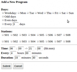
The idea is that you can define many ‘schedule items’, each of which consists of Time (which can be a weekly schedule, odd or even day schedule, or every N day schedule), selection of stations, start time, end time, interval, and duration (down to seconds). You can add as many such items as you want, subject to the EEPROM size. These pages are not looking beautiful yet, but with the trick mentioned above, they can potentially look much more fancy.

Something else I’ve been working on is reverse engineering RF signals sent from remote temperature and humidity sensors as well as wireless rain sensors. There are lots of these off-the-shelf remote sensing transmitters that you can buy at very competitive price in retail stores. These transmitters typically work in 434 MHz RF range. I’ve found a simple method to reverse engineer their RF signals, and I’ve successfully decoded data from a temperature and humidity sensor. Hopefully I will be able to figure out the rain sensor as well. It has been great fun, and I will devote a couple of posts soon to describe how I did it.

All right, so much for today!
OpenSprinkler Interval Schedule Program First Version Released

The initial version of the interval schedule program is now available for download in my GitHub page:
https://github.com/rayshobby/opensprinkler

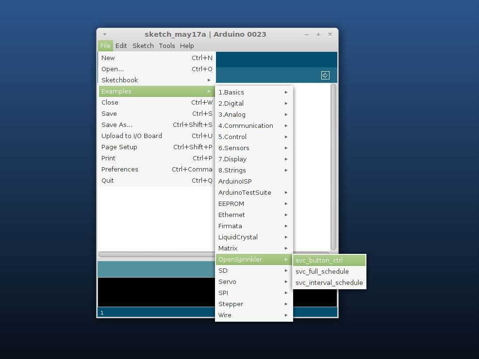
Note that all demo programs are moved to the Libraries->OpenSprinkler->examples directory. This makes it easy to load a demo program in Arduino. For example, once you put the OpenSprinkler library in your Arduino’s Libraries path, you can access a demo program by following the screenshot below:

And here is a screenshot of the interval schedule program:

Basically, it allows you to set an interval and duration for each station. In the above example, stations 1 and 2 are scheduled to be on for 20 seconds every 4 hours, stations 3 and 4 are scheduled to be on for 20 seconds every 6 hours, and the remaining four stations are scheduled to be on for 5 minutes every 50 minutes. So it’s pretty simple.

An added feature is that if more than 1 stations are scheduled to be on at the same time, they will be serialized: in other words, the controller will turn on each station one after another instead of simultaneously. The serialization is activated by setting the Multi-Station value to 0.

The program is still in a primitive state, and I am working to strengthen it so that it can support a weekly schedule. Basically, the idea is to allow the user to add any number of schedule items, where each item contains a list of selected stations, days in a week, start time, end time, interval, and duration. For example, you can specify an item like ‘schedule stations 1, 2 and 5 for every Monday and Wednesday, start at 8am and end at 6pm, turn them on for 5 minutes every 4 hours’. You can add as many schedule items as you want, or modify them later. This will make the OpenSprinkler schedule algorithm significantly more flexible and powerful. So stay tuned!

OpenSprinkler v1.2u to Debut at Maker Faire Bay Area this weekend

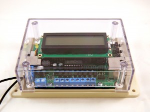
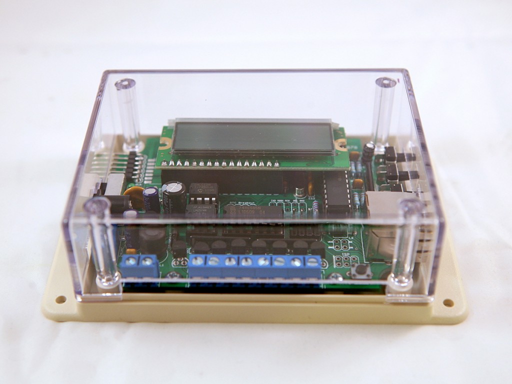
Yup, you heard it right, version 1.2u of OpenSprinkler will debut at Maker Faire Bay Area on May 19 and 20. If you are going to Maker Faire, you are welcome to drop by and see our live demos. I started working on v1.2u shortly after releasing v1.1, and we were lucky to get the PCBs and components just in time for Maker Faire. The PCBs and components are shipped directly there, so it is not yet available for online purchase until May 23. But it is available for purchase at the Maker Faire and will be available online shortly after that.

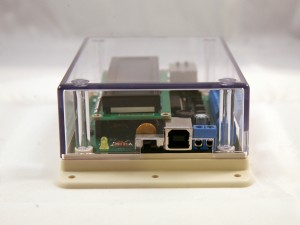
So what’s new in this version? The main improvement is an on-board USB programmer. Specifically it’s a USBtiny ISP programmer built on a pre-programmed ATtiny45. USBtiny is one among many choices to directly program an AVR microcontroller without using a bootloader. The main advantages are that it is low cost (costs just a couple of dollars) and it enables the entire program space on ATmega328 (since no bootloader is needed). It is based on a post by Tequals0 and this version makes use of the internal clock and PLL on ATtiny45 to implement USBtiny with only three external resistors. Very elegant. With the on-board USB programmer, you don’t need any external programmer any more. Note that this version is named v1.2u, where u refers to the USB connectivity.

The second change is that some components have been replaced to adopt more common parts, including the switching regulator, the Ethernet jack, and the LCD. Also, there is now a rain sensor screw terminal, and a pinout for sensing power loss. The program will be updated to support these features soon. Another change is that the LCD pin assignment is slightly modified to free up analog pin 1, which is useful for talking to sensors. Finally, the extension board connector is also updated to use more common 2×3 pin header and cable. Note that this is still compatible with the previous version of extension board. If you have the previous version of extension board, it still works with v1.2u by switching a pin on the extension cable.

If you are interested, check the detailed release notes here and the release video below.

A New Way to Interface with Remote Power Switches

Update: check out the RFToy — an easy-to-use standalone gadget to control remote power sockets. Also, support for remote power sockets have been added to OpenSprinkler firmware 2.1.1.

Note: the RF transmitter used in this article is available for purchase in the shop page.

In a previous post I described a way to use an Arduino to interface with remote controlled power sockets. The idea was to make use of the original remote control, and a high-side transistor switch to simulate button presses. This approach is generic: you don’t need to know how the remote control signal is encoded, instead, just treat the remote control as a black box and simulate the button presses. However, the downside of this approach is that it requires soldering wires and components to the remote control, which is quite a bit of work.

Update: check out the RFToy — an easy-to-use standalone gadget to control remote power sockets. Also, support for remote power sockets have been added to OpenSprinkler firmware 2.1.1.

Recently, inspired by the JeeLabs KAKU remote switch article, I figured out a new way to interface with these remote power switches. The method published by JeeLabs uses an RFM12B transceiver, which is cool because my OpenSprinkler design has a reserved spot for RFM12B. Unfortunately after many experiments I was unable to get it to work with my switches. However, I did succeed by using a 433MHz RF transmitter purchased from SparkFun. So below I document the process of how I did it.

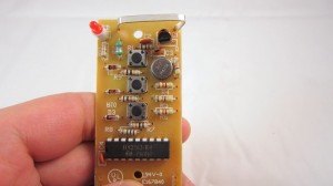
To begin, I took apart the remote control. The goal is to reverse engineering the signal sent from the remote control, so that I can use an Arduino to simulate the same signal. This will allow me to use a program to control the power sockets. The schematic of the remote control circuit can be found in the previous post. Basically it consists of an encoder IC (HT2262 or PT2262) and a 433MHz RF transmitter circuit.

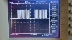
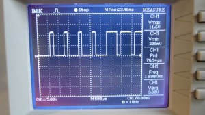
By connecting an oscilloscope to the circuit I was able to analyze the signal patterns. Details can be found in the video attached at the end of this post. Below are the patterns I observed when button 1 is pressed (corresponding to power socket 1).

The signal consists of two basic patterns: a short HIGH followed by a long LOW, which I call a ‘0’ all together, and a long HIGH followed by a short LOW, which I call ‘1’. The long part is roughly 500us and the short part is roughly 160us (so it’s about a 3:1 ratio). Each signal sequence consists of 25 bits: the first 16 bits are always ‘0000 1111 0101 0101’, which I call the ‘signature’; and the next 8 bits are the ‘command’, which correspond to the index of the power socket; finally, there is always an ending ‘0’.

For example, the entire sequence to toggle socket 1 is

0000 1111 0101 0101 1100 0001 0

the entire sequence for socket 2 is:

0000 1111 0101 0101 0011 0001 0

and for socket 3 it is:

0000 1111 0101 0101 0000 1101 0

Again, a ‘1’ means a 500us HIGH followed by a 160us LOW, and a ‘0’ means a 160us HIGH followed by a 500us LOW. When a button is pressed, the sequence is repeated several times, for robustness I guess.

Interestingly, you can OR the command part in order to toggle two or three sockets at the same time. For example, the sequence below will simultaneously toggle socket 1 and 2:

0000 1111 0101 0101 1111 0001 0

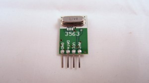
Next, to simulate the remote control signal using an Arduino, I used a 434MHz RF transmitter from SparkFun. This transmitter has only 4 pins: Gnd, Vcc, Antenna, and Data. The data pin can be connected to any digital pin on the Arduino in order to send the control sequence as analyzed above.

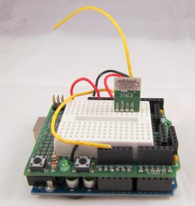
For demonstration, I used Arduino pin 10 to send the control sequence through the Data pin. The connection is as follows: VCC->+5V, GND->GND, DATA->Digital 10, ANT->a short wire. The supply voltage for the RF transmitter can be anywhere between 1.5V to 12V. The higher the voltage, the longer the transmission range. Normally 5V should be good for at least 15-20 meters. If you want the highest range, use a +12V power adapter to power your Arduino, and connect the RF transmitter Vcc pin to the Arduino VIN pin. Alternatively, you can add a voltage boost converter to bump +5V to +12V.

Below you can download the Arduino program I wrote. The code should be easy to follow.

If you have a different remote controlled power switch, you can follow the same procedure to find out the control sequence, then modify the program accordingly. A video demo is provided below:

Credits: the method is based on JeeLabs KAKU remote switch and the code is based on the kaku_demo sketch included in their RF12 Arduino library.

Note: the RF transmitter (434MHz) is available for purchase in the shop page.


Update 1: apparently if you look at the datasheet of PT2262, which I found a copy here, it explains how the encoding pattern is computed. The ‘signature’ part has to do with the status of each pin from A0 to A7 on PT2262 – whether the pin is connected to GND, VCC, or floating, and the ‘command’ part is determined by the status of each pin from D0 to D3. I compared the circuit with the datasheet and verified that the pattern I observed from the oscilloscope matches the calculation. Also, according to the datasheet and the resistor value I found on the remote control, it looks like the long delay should be about 400us and short delay 133us, which is a bit different from the 500us and 160us observed from the oscilloscope. Also, the ending ‘0’ in my sequence turns out to be a ‘sync’ bit, which is 133us high followed by 4200us low. The fact that my original sketch has worked means there is a some level of tolerance in the timings. So they do not have to be highly accurate.

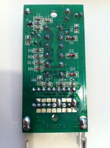
Update 2: new version of remote control. A reader of this post, Chuck, sent me a question that the sketch doesn’t seem to work with his remote control. After researching this issue, we found that the new version of the remote has changed to use SMT components and also has changed the coding pattern. Chuck sent me an image of the back of the PCB. From the image and the datasheet of PT2262, I figured out the new coding pattern. Basically, the ‘signature’ part of the code has been changed from

0000 1111 0101 0101

to

1101 0111 0101 0101

More technically, the coding pattern can be derived from the connections of Pins 0-7 of PT2262. In the newer version (from the PCB image on the left), the first 4 pins are connected as HIGH, FLOAT, FLOAT, HIGH, whereas the older version is connected as LOW, LOW, HIGH, HIGH. Here HIGH means connected to Vcc, LOW means connected to Ground, FLOAT means unconnected. Taking a look at the datasheet, you can easily figure out the actual code: LOW -> 00, HIGH -> 11, FLOAT: 01.

Chuck sent me his modified code, which you can download here.


OpenSprinkler is going to Maker Faire Bay Area

You heard it right: we are going to this year’s Maker Faire at San Mateo, California on May 19 & 20!

Maker Faire 2012

We will be giving live demonstrations of the OpenSprinkler, AASaver, and two exciting upcoming open-source projects: OpenSprinkler Bee (battery-operated sprinkler controller), and SquareWear (a compact wearable electronics platform). If you are planning to go to Maker Faire, please make sure to drop by our booth (Maker # 7870). If you haven not decided, Maker Faire is a really fun event. You won’t regret it. So make your travel plan today!

Arduino Encounter

I went to a local cafe for brunch today, and I couldn’t be more delighted to see this poster at the cafe:

So is this where the name ‘Arduino’ came from? Not really. According to Wikipedia, the name of the open-source microcontroller Arduino comes from the following:

Founders Massimo Banzi and David Cuartielles named the project after Arduin of Ivrea, the main historical character of the town.[8] “Arduino” is an Italian masculine first name, meaning “strong friend”. The English version of the name is “Hardwin”.[9]

The poster is actually an advertising poster made by Italian artist Leonetto Cappiello. The painting was done in 1922 for La Victoria Arduino. There are apparently multiple posters, which you can find here. In any case, a pleasant surprise to find the name of my friend ‘Arduino’ on the poster 🙂

OpenSprinkler v1.1 Released

After several weeks of hard work, I am excited to announce that OpenSprinkler v1.1 is now available!

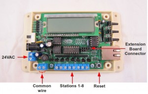
So what’s new in this version? The biggest improved feature is hardware support for arbitrary (>8) number of stations through extension boards. This was actually quite easy to implement: the main hardware change is added pinouts for the 74HC595 shift register, which allows cascading additional shift registers to expand the number of stations. The latest software has also been updated to generically support any number of stations. So this leads to a very economic way to expand the number of stations, which is often very expensive with commercial sprinkler timers.

Another change is that the station terminals now use a common wire + individual station wire design, compatible with commercial sprinkler timers.

Other minor changes include an added 750mA fuse for current protection, and added RTC pinouts to support external I2C RTC breakout board.

Check detailed Release Notes here. The kit is now available in my hobby shop. You can get it either as a DIY kit, or a fully assembled and tested product. Detailed assembly instructions can be found here.

V1.1 Update Video

Link to the previous (v1.0) release video.


OpenSprinkler Software Update

The OpenSprinkler software (specifically svc_demo and vc_simple_web) have been quite outdated since October last year, and I am increasingly unhappy with the issues in them. I’ve also received several requests for added features and improved user interface. Over this weekend, I have finally pulled myself together and made some updates to these programs. Here is a list of major changes:

  • Created the OpenSprinkler Arduino library, which makes it easy for code re-use.
  • Added support for arbitrary number of stations. This is probably one of the most common features requested, and it’s now generically supported in software. This will go well with the upcoming hardware update v1.1. The main additions of v1.1 are on-board pinouts and connectors to link extension boards. Each extension board consists of just a shift register, triacs, resistor networks and terminal blocks. So this is a simple and inexpensive way to scale up to potentially a large number of stations.
  • Added a self-test mode and removed the manual schedule mode. The self-test mode can be activated by holding button B1 during startup.
  • External EEPROM now stores data in NOT format (i.e. ~value instead of value), eliminating the un-initialized EEPROM issue.
  • The new svc_button_ctrl and svc_full_schedule programs. These make use of the new OpenSprinkler library and replace the previous svc_simple_web and svc_demo programs (which are now in the archived folder).

You can get a copy of the updated programs from my GitHub download page. They are backward compatible with the previous version of OpenSprinkler, so you can feel free to give them a try on your current hardware.

In order to use the OpenSprinkler library, just copy the library folder to your Arduino’s libraries directory, and then in your main code, add:


#include<OpenSprinkler.h>
OpenSprinkler svc;
void setup() {
  svc.begin();
  svc.options_setup();
}

This will create an OpenSprinkler object called svc. Check OpenSprinkler.h in the library folder for all class member functions, and the svc_button_ctrl and svc_full_schedule for examples of writing your own code. A few simpler examples will be added to the library later.

The hardware update v1.1 will be available in a week or so. I am still finishing up some documentations, but that shouldn’t take long.

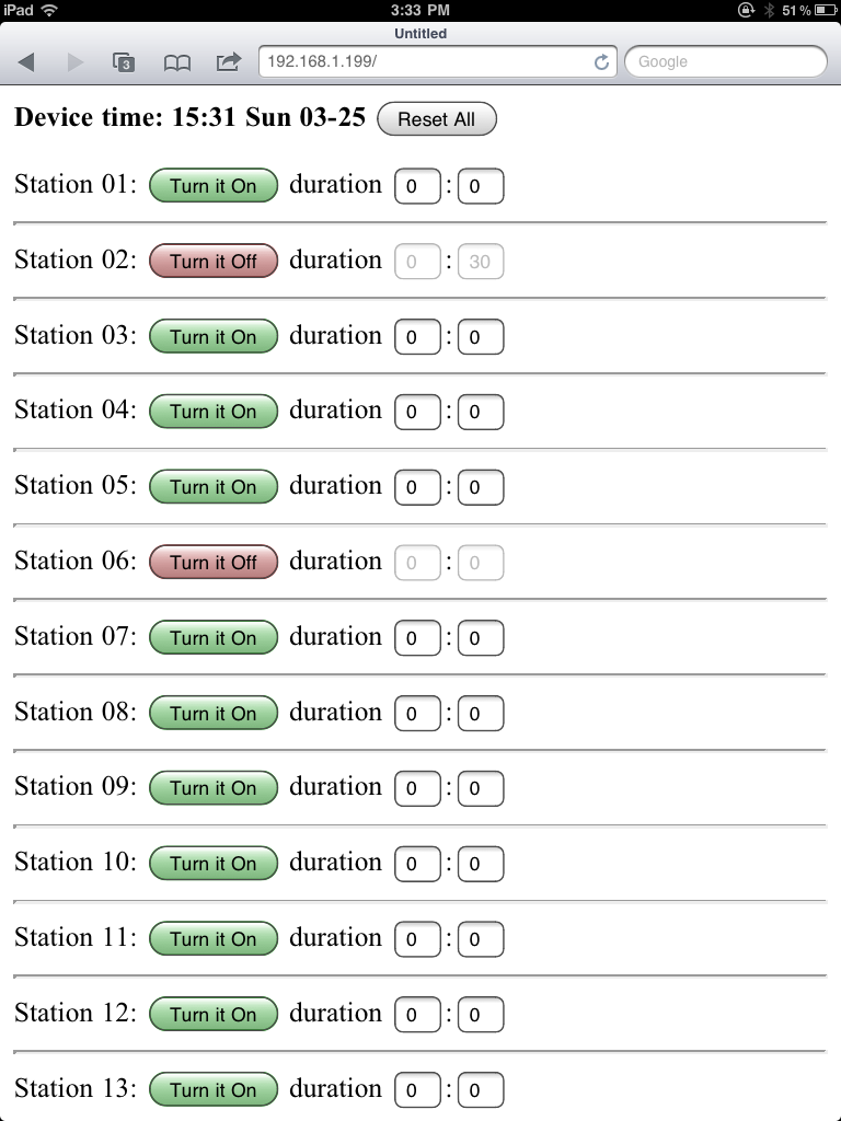
For the curious ones, here are some screen shots of webpages from the new programs. These examples show 24 stations:

svc_button_ctrl

svc_full_schedule

Building a simple testing circuit with Pogo pins

When you are making products in batches, you need a quick way to test them and make sure they function as expected. For example, three weeks ago, I sold close to 100 AASaver kits in a day, and I needed a good way to automate the testing before they are shipped out:

Well, this is what pogo pins are good for. So what is a pogo pin? It’s basically a spring-loaded pin that you can use to make a secure and temporary contact with your circuit board. It allows you to stack the testing circuit directly onto the target circuit, without any additional soldering. The picture on the right above shows an example I got from eBay. This is of model number P75-E, which is 1.02mm in diameter and 16.5mm in length, perfect for the AASaver circuit board.

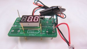
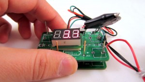
To build a tester, I need to: 1) provide input power to the target board; 2) test the output voltages (5V/3.3V); and 3) test the output current (>300mA). These can be done by making use of an existing AASaver PCB. I used a total of 5 pogo pins. Two are soldered into the battery holes to provide input power from two AA batteires; two are soldered into the Vcc and Gnd, and further connected to a mini voltage meter for testing output voltages; and one more to provide weight balance. See the pictures below.

To use the tester, I simply stack it onto a target board, and check the voltage readings. Each test can be done in less than 8-10 seconds. To test the output current, I added a 15 Ohm power resistor and a slide switch onto the testing circuit. When the switch is turned on, the power resistor is applied between Vcc and Gnd, which causes an output voltage to drop. This drop should be relatively small (<0.3V) if the target board meets the current rating (>300mA). So there you go: a simple tester for the AASaver!

AASaver Kit v1.1 is in stock

AASaver kit is now back in stock. There was a bit of delay in the shipping, but it has finally arrived! The funny thing is that the updated version (v1.1) arrived ahead of the original version, so if you place an order now, you will received the updated version, with additional features, at the same price!

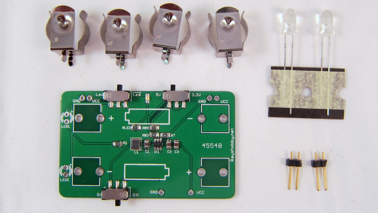
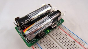
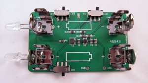
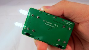
Picture of v1.1

Here is the list of changes in v1.1:

  • Moved both flash LEDs to the same side so they point to the same direction.
  • Added an on-board resistor (R1) for the flash LEDs.
  • Added a separate flash LED switch.
  • Moved the power switch to the bottom side.

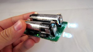
These changes were made to improve the usability. For example, the separate LED switch allows you to use it simultaneously as a breadboard power supply and flashlight (previously it was either one or the other). Also, the two LEDs now point to the same direction, so it can function better as flashlights.

The kit is available in my hobby shop. As I said, if you place an order now, you will get the updated v1.1 at the same price, until it runs out.