Using 24V AC Relays with OpenSprinkler

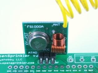
Back in early December last year, we introduced a new feature in OpenSprinkler Firmware 2.1.1 that allows OpenSprinkler to directly talk to remote power sockets. With this feature, you can use OpenSprinkler to not only switch sprinkler valves, but also switch powerline devices such as light, pump, heater, fan. While it’s a powerful feature, it is after all a wireless solution so it’s not the most reliable — sending wireless signals to remote power sockets is prone to interference and is limited by distance and barriers (e.g. walls, floors) in between.

If you still prefer using relays, whether because it’s more reliable, or because it’s the classic way, there are plenty of choices. I’ve often received questions about how to use OpenSprinkler with a relay. The easiest solution is to get a 24V AC relay. Then you can wire it up as if it’s a sprinkler valve — when OpenSprinkler turns on the corresponding station, the relay is activated, and that turns on the device connected to the relay. Because AC relays are not as common as DC relays, they tend to be more expensive. Here I list three choices I’ve found:

1. Omron G7L-2A-TUB-J-CB-AC24: this is available on Amazon. This is actually commonly used in sprinkler pump start relays — if you have a pump start relay, you can open it up and check if it has a 24V AC relay in side. This particular one has a contact rating of 25A @ 220VAC, which is sufficient for most applications. You can also find similar ones with different specifications: if you search for ‘Omron G7L-‘ you will find many choices, look for the ones ending with AC24, which are the 24V AC versions.

IMG_0659IMG_0661

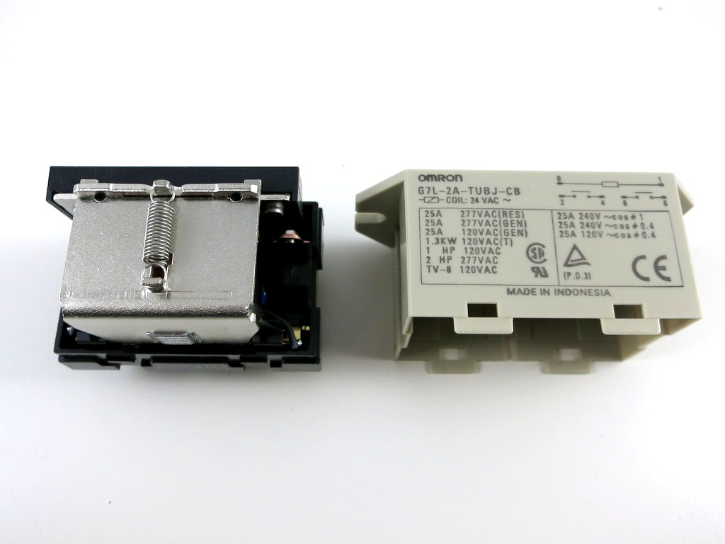
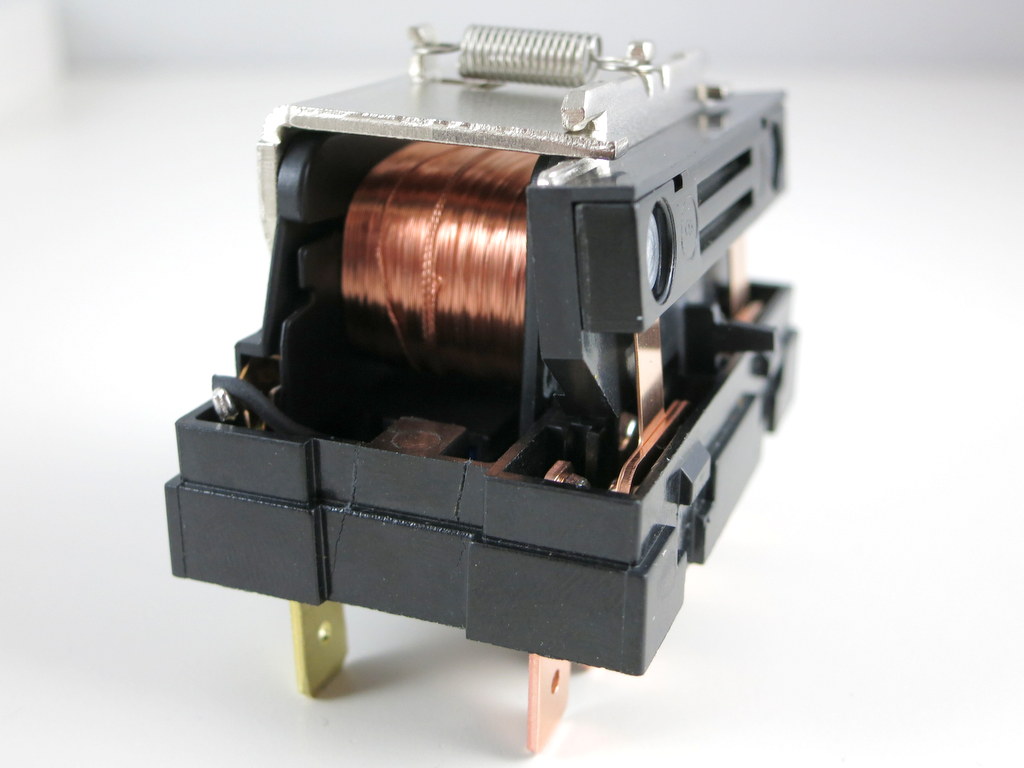
I am quite curious how such 24V AC relays work. It probably is constructed somewhat differently from a DC relay. So I ventured to open it up. As you can see in the picture on the right above, it has a big coil, a contact piece connected via a spring. When voltage is applied on the coil, the contact piece gets attracted and therefore connecting two contact pins together. That’s how a basic relay works.

Something strange I noticed is that when I try to measure the resistance on the coil, it gives me a very large value — several mega-ohms. The coil resistance can’t be that large. There is probably additional circuitry inside the relay. I then measured the forward voltage drop on the coil, at either polarity it gives about 1.25V drop, which strongly indicates there is a bridge (i.e. full-wave) rectifier inside. This makes sense, because a bridge rectifier is a standard way to convert AC to DC. So the additional ‘construction’ inside the AC relay (compared to DC) is probably the rectifier.

To verify it, I had to open it up even further, which involves cutting some pieces of the plastic. Eventually I was able to open it up completely. Check the bottom section of the relay:

IMG_0660

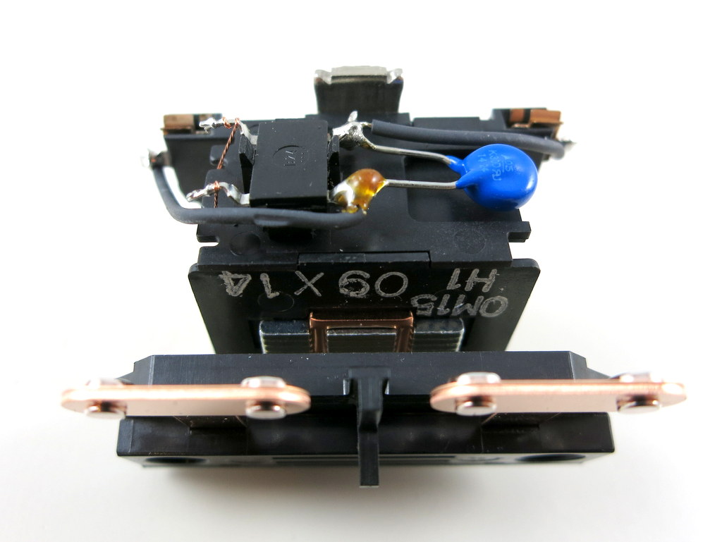
Yup, there is a bridge rectifier and a MOV. Previously I was measuring the resistance through the bridge rectifier, which explained why the value I got was incorrect. Now I can measure the real resistance of the coil, which turns out to be about 294 ohm. That’s about right — under 24V AC, it will draw an average of about 80 mA AC current, which matches the specification.

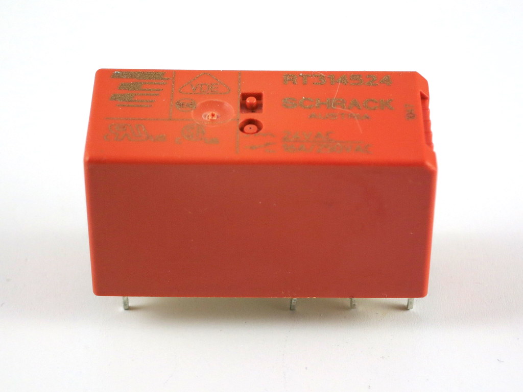
So in case you are looking for a 24V AC relay to work with OpenSprinkler in order to switch high-voltage devices, this is an inexpensive (<$10) choice and is easy to find. 2. Schrack RT314524: This is a very small 24V AC relay that you can buy from Mouser or Digikey. It has a contact rating of 16A @ 250VAC, which is also plenty for common applications.

IMG_0662

3. Other choices: There are some other choices which were brought up on the forum, including a open-style panel mount 24V AC relay, and even solid-state relays (SSRs).

In any case, if you are looking for a relay to work with OpenSprinkler, the above are the ones worth considering.

Work in Progress: OpenSprinkler Pi (OSPi) A+ will Finally Close the Gap

When I first had the idea to design OpenSprinkler Pi (OSPi), a secret motivation was that one day I figured out how to fit Raspberry Pi into the existing OpenSprinkler enclosure. Yes, it sounds silly, and you can laugh at it; but if you understand how much it costs to make an injection molded enclosure, and how difficult it is to predict the market and demand, you will see why I wasn’t quite ready to invest on a whole new enclosure for OSPi.

The experience last year has proven that OSPi is quite popular. I really enjoyed seeing the amount of community development on it, primarily due to the low cost of RPi and the flexibility in programming the RPi. We’ve also seen continued evolution of RPi, from the early A and B models to B+ and more recently A+. On the plus side, it’s exciting to see that RPi continues to become smaller and cheaper. The A+ version is now 25% smaller and you can get one for just $20. On the other hand, I am sure the different versions created some challenges in re-designing products powered by RPi. Because each version has different peripheral elements, size, screw hole locations, it’s quite difficult to design one board that fits all versions.

So in a way, I felt lucky that I wasn’t too hasty to invest on a dedicated enclosure for OSPi, because whatever I would have designed would probably not fit A+ in the end. But the lack of a dedicated enclosure has always been the major confusion about OSPi: from time to time I receive questions about why the cutouts on the enclosure do not match RPi, and then I have to explain. It’s not ideal.

Here comes the good news: with RPi A+, it looks like I may be able to ‘close the gap’ finally — that the injection-molded OpenSprinkler enclosure will finally fit OSPi, without confusing mis-alignment of the cutouts, and with buttons and LCD, just like the microcontroller-based OpenSprinkler!

Here are some pictures to show you the proof-of-concept:
IMG_0582IMG_0583
IMG_0584IMG_0585

Mounting RPi. The most dramatic change is that RPi A+ will be mounted at the back of the OSPi circuit board. This is necessary to make space for the LCD (explained below). This may look surprising, but because A+ is quite flat, there is sufficient space at the back of OSPI to fit it, except HDMI, USB, and other peripheral connectors, which I’ve made cutouts for.

There is no secret that I’ve always enjoyed solving the ‘how to fit RPi into the OpenSprinkler case’ problem. It’s like a geometry puzzle for me. Often constraints push me to think of new solutions. So bear with the nerdy side of me 🙂

LCD. Next, for the LCD I am using I2C LCD — it’s the standard 1602 LCD with a I2C module at the back. This turns out to be very important, because I2C LCD needs only 4 pins in total (VCC, GND, SDA, SCL), significantly reducing the pin requirement and saving space. You can buy these with pre-soldered I2C modules, at very small added cost.

Buttons. There is also space to fit 3 push-buttons on the right-hand side of the circuit board. The physical buttons can be quite useful for triggering events or performing manual sprinkler control.

Ethernet. Lastly, I don’t want to waste the cutout for Ethernet jack, so I even added a ENC28J60 Ethernet controller. This is a useful add-on for RPi A+, which doesn’t come with an Ethernet jack itself. It took me quite while to figure out how to re-compile the RPi kernel to support this Ethernet controller. Don’t expect it to be very fast, but it comes handy if you really need wired Ethernet connection. Most people will still prefer the WiFi dongle.

IMG_0586

One of the biggest drawback of this design is that RPi A+ will now be permanently soldered onto OSPi, because there is simply no space in height to put pin headers. This is not ideal but I can’t think of a better choice. The other potential issue is the heat dissipation of RPi — although there is some space between RPi, OSPi, and the enclosure bottom, it can become an issue during hot summer days. There is some space on the board to make vent holes, so I will see what I can do.

To summarize, this is a proof-of-concept design for OSPi A+ — it will finally make the injection-molded enclosure work perfectly for OSPi. Because this is a very early prototype, don’t expect it to be available anytime soon, although I do hope to make it ready by summer time this year.

Feedback, comments, and suggestions are welcome. Thanks!

OpenSprinkler Firmware 2.1.1 New Feature: Control Remote Power Sockets

In the past I’ve written several blog posts about how to use Arduino to interface with remote power sockets. For home automation involving powerline devices (e.g. lights, heaters, pumps, fans), this is my favorite solution, because it’s low-cost (remote power sockets are widely available at cheap price) and convenient (no messing around with relays and powerline wires). Also, one Arduino plus transmitter can simultaneously talk to many power sockets, making this a scalable solution too.

With the just released OpenSprinkler firmware 2.1.1, support for interfacing with remote power sockets has finally arrived. So you can now use OpenSprinkler not only to control sprinkler valves, but also powerline devices. Trying to find a programmable way to control your Christmas lights? Look no further! With OpenSprinkler’s easy-to-use web interface and flexible programming capability, you can enable automated control of lights, heaters, pumps, fans — anything that can be plugged into wall outlets.

Here is a quick video tour on how to get started:

Below are detailed instructions.

Required Parts:

How does this work?
Let me briefly explain how the whole thing works. First, common remote power sockets operate in the 433MHz radio frequency band. When you press a button on the remote, it sends out a signal to the power socket, which gets decoded and acted upon. If we can sniff the signal, we can use a microcontroller plus a 433MHz transmitter to replicate the signal, thus be able to directly control the power socket in software. The RFToy is a gadget that I’ve designed to easily decode signals from common remote power sockets. Once we have the code, we can use OpenSprinkler to simulate the code, thus be able to control remote devices.

Heads-up: the following steps require a small amount of soldering. The estimate time for modification is 15 to 20 minutes.

Step 1: Decode Remote Power Sockets
Take out the RFToy, plug in a 433MHz receiver (making sure the VCC and GND pins on the receiver match the +5V and GND pins on the RFToy). Follow the on-screen instructions to record the on/off signal of a power socket. Once decoded, the signal will be converted to a 16-character hexademical code.

To test if the code works, take out the 433MHz transmitter, and solder a 17cm (6.7inch) long wire antenna to the ANT pin. Then plug it into the RFToy (making sure the DATA and GND pins on the transmitter match the DATA and GND pins on the RFToy). Bend the pins as necessary. Now click button S3 or S1 on the RFToy, the power socket should be toggle on or off just like when you press the buttons on the remote. Keep in mind that although most remote power sockets work in the 433MHz band, there are some that work in the 315MHz band. In that case, just use a 315MHz transmitter-receiver pair.

Step 2: Install RF Transmitter to OpenSprinkler
Remove the OpenSprinkler enclosure, and locate the RF transmitter pinouts (marked A3 VIN GND). The pinouts are located either close to the top of the PCB, or next to the Ethernet jack. Plug in the transmitter to the pinouts, making sure the DATA-VCC-GND pins on the transmitter match the A3-VIN-GND pins on the circuit board. Then solder the three pins at the back of the circuit board, and clip as necessary. Carefully arrange the wire antenna around the LCD and re-install the enclosure.

It’s important to use a wire antenna of sufficient length, otherwise the transmission range will be severely limited.

Step 3: Final Testing
Make sure your OpenSprinkler is running firmware 2.1.1 or above. If not, please follow the firmware instructions to upgrade your firmware first. Then go to Edit Stations, select the station you’d like to use as an RF station, and change its name to the 16-character hexademical code recorded on the RFToy. Any station with a name of this form will be automatically recognized as an RF station. When the station is turned on, the controller will automatically send out the signal through the installed RF transmitter, thus turning on the corresponding power socket (and vice versa for turning off the station).

Three quick notes:

  • The normal station function still works (i.e. if there is a sprinkler valve connected to that station, it will be switched on/off accordingly).
  • Most likely you want to turn off the ‘sequential’ flag for RF stations. This is because unlike sprinkler stations, you probably don’t want RF stations to be serialized with other stations.
  • If you are short of stations, just increase the number of expansion boards. You don’t need to have the physical expansion boards (think of RF stations as virtual sprinkler valves). Firmware 2.1.1 supports up to 48 stations in total.

With this feature, you can now use OpenSprinkler to programmably switch a large number of powerline devices, such as Christmas lights, landscape lights, water pumps, heaters, fans.

Keep in mind that because this is still an experimental feature, don’t use it on anything critical (i.e. those that can cause damages if accidentally left on). Depending on the distance and obstacles between OpenSprinkler and remote power sockets, it might not reliably switch on/off power sockets. So take time to do plenty of testing before you finalize the setup.

os_rf_install

That’s it. We encourage you to try out firmware 2.1.1 and let us know your comments / suggestions / feedback. Don’t forget to post pictures of your projects. We would greatly appreciate your efforts. Thanks!