When I first had the idea to design OpenSprinkler Pi (OSPi), a secret motivation was that one day I figured out how to fit Raspberry Pi into the existing OpenSprinkler enclosure. Yes, it sounds silly, and you can laugh at it; but if you understand how much it costs to make an injection molded enclosure, and how difficult it is to predict the market and demand, you will see why I wasn’t quite ready to invest on a whole new enclosure for OSPi.
The experience last year has proven that OSPi is quite popular. I really enjoyed seeing the amount of community development on it, primarily due to the low cost of RPi and the flexibility in programming the RPi. We’ve also seen continued evolution of RPi, from the early A and B models to B+ and more recently A+. On the plus side, it’s exciting to see that RPi continues to become smaller and cheaper. The A+ version is now 25% smaller and you can get one for just $20. On the other hand, I am sure the different versions created some challenges in re-designing products powered by RPi. Because each version has different peripheral elements, size, screw hole locations, it’s quite difficult to design one board that fits all versions.
So in a way, I felt lucky that I wasn’t too hasty to invest on a dedicated enclosure for OSPi, because whatever I would have designed would probably not fit A+ in the end. But the lack of a dedicated enclosure has always been the major confusion about OSPi: from time to time I receive questions about why the cutouts on the enclosure do not match RPi, and then I have to explain. It’s not ideal.
Here comes the good news: with RPi A+, it looks like I may be able to ‘close the gap’ finally — that the injection-molded OpenSprinkler enclosure will finally fit OSPi, without confusing mis-alignment of the cutouts, and with buttons and LCD, just like the microcontroller-based OpenSprinkler!
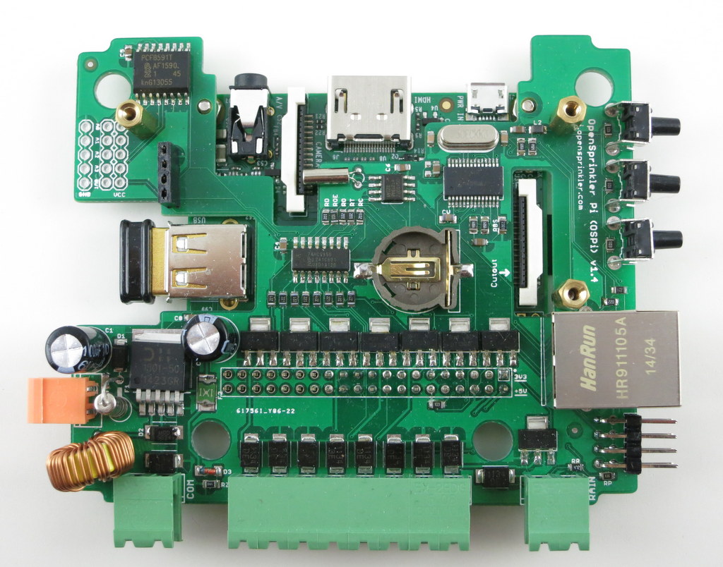
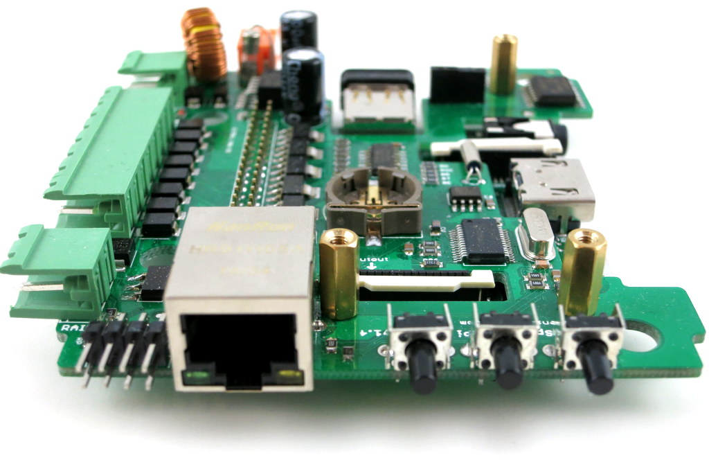
Here are some pictures to show you the proof-of-concept:
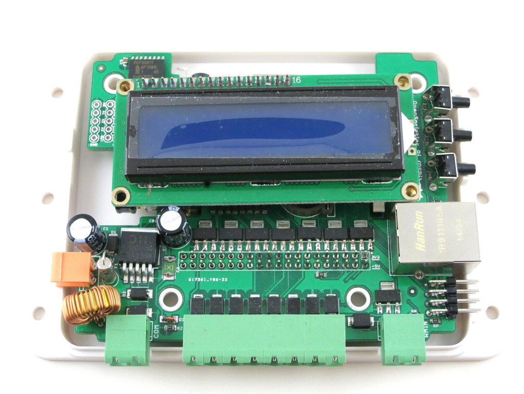
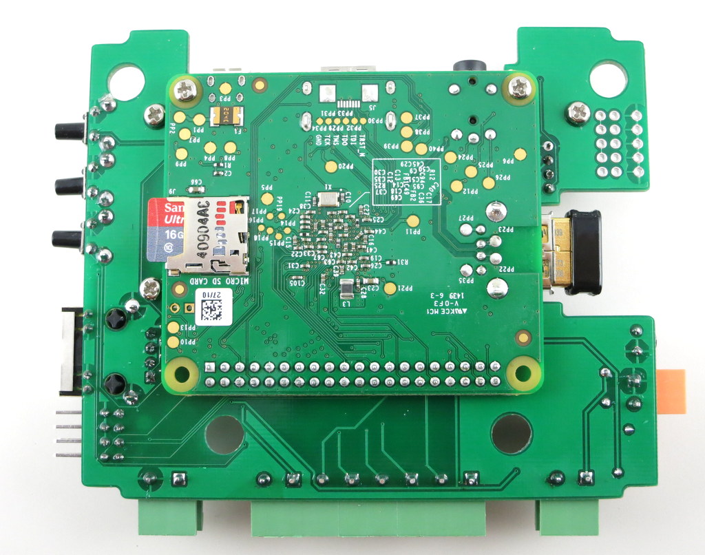

Mounting RPi. The most dramatic change is that RPi A+ will be mounted at the back of the OSPi circuit board. This is necessary to make space for the LCD (explained below). This may look surprising, but because A+ is quite flat, there is sufficient space at the back of OSPI to fit it, except HDMI, USB, and other peripheral connectors, which I’ve made cutouts for.
There is no secret that I’ve always enjoyed solving the ‘how to fit RPi into the OpenSprinkler case’ problem. It’s like a geometry puzzle for me. Often constraints push me to think of new solutions. So bear with the nerdy side of me 🙂
LCD. Next, for the LCD I am using I2C LCD — it’s the standard 1602 LCD with a I2C module at the back. This turns out to be very important, because I2C LCD needs only 4 pins in total (VCC, GND, SDA, SCL), significantly reducing the pin requirement and saving space. You can buy these with pre-soldered I2C modules, at very small added cost.
Buttons. There is also space to fit 3 push-buttons on the right-hand side of the circuit board. The physical buttons can be quite useful for triggering events or performing manual sprinkler control.
Ethernet. Lastly, I don’t want to waste the cutout for Ethernet jack, so I even added a ENC28J60 Ethernet controller. This is a useful add-on for RPi A+, which doesn’t come with an Ethernet jack itself. It took me quite while to figure out how to re-compile the RPi kernel to support this Ethernet controller. Don’t expect it to be very fast, but it comes handy if you really need wired Ethernet connection. Most people will still prefer the WiFi dongle.
One of the biggest drawback of this design is that RPi A+ will now be permanently soldered onto OSPi, because there is simply no space in height to put pin headers. This is not ideal but I can’t think of a better choice. The other potential issue is the heat dissipation of RPi — although there is some space between RPi, OSPi, and the enclosure bottom, it can become an issue during hot summer days. There is some space on the board to make vent holes, so I will see what I can do.
To summarize, this is a proof-of-concept design for OSPi A+ — it will finally make the injection-molded enclosure work perfectly for OSPi. Because this is a very early prototype, don’t expect it to be available anytime soon, although I do hope to make it ready by summer time this year.
Feedback, comments, and suggestions are welcome. Thanks!