Verified: OpenSprinkler Pi (OSPi) 1.4 works with Raspberry Pi A+

As you’ve probably heard: the Raspberry Pi Foundation recently released RPi A+, which is the first RPi that’s smaller in size than any other RPi. It is essentially a B+ with less memory (256 MB vs. 512 MB), one USB port (instead of four), and a compact form factor (65mm vs. 85mm). Not only is it smaller, but it’s lighter, consumes less power, and best of all, it’s cheaper — only $20!

There is a famous Chinese saying: “A sparrow may be small but it has all the vital organs”. This is exactly what I feel about RPi A+. Although it’s almost 25% smaller than any other RPi, it retains all the essential features. Similar to B+, it has a microSD card slot, and hybrid audio / composite video port. This helps reduce the overall size of the assembly. It doesn’t have a built-in Ethernet controller and connector (which contributed to the lower price tag), but most people will likely use a USB WiFi dongle anyways so it’s not a big loss. What’s clever about its design is that it’s pin compatible with B+ — in fact it’s basically B+ with 20mm chopped off from the right edge. All the connectors, pin headers, screw hole locations are exactly the same as B+. This means any shield / extension board that works for B+ is likely to work for A+ with no modification.

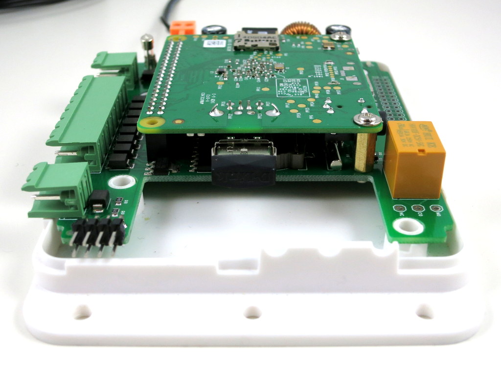
Such is the case with OpenSprinkler Pi (OSPi) — the B+ version works perfectly fine for A+. Below are two pictures showing OSPi v1.4 (B+ version) with A+ installed. As you can see, it leaves extra space on the right-hand side to fit additional components.

IMG_0484IMG_0485

As you may have guessed: given the extra space, the first components I will consider adding are three pushbuttons. This makes a lot of sense. So far OSPi has been using the same enclosure as the microcontroller-based OpenSprinkler. Because the enclosure is unfortunately not tailored to OSPi, there are several cutouts left unused, such as the pushbutton cutouts, Ethernet, LCD, USB, and power switch. With the extra space on the right, pushbuttons are the easiest to add back. Ethernet controller and connector can also be added, although as I said above I am not sure how useful they are, since most people would probably prefer using USB WiFi dongle.

LCD is another popular feature that has been requested. This is a bit tricky to add because there is simply not enough space in height to fit a standard 1602 LCD like the microcontroller-based OpenSprinkler. However, I’ve got a wild idea that I think is going to work. If this is feasible, then OSPi will truly look just like the microcontroller-based OpenSprinkler. I will post an update as soon as my idea is verified. Stay tuned!

Sneak Peak Preview of SquareWear Esimal

Since SquareWear 2.0 and Mini, there will soon be a new member in the SquareWear family. This is a sneak peak preview of SquareWear Esimal — the tiniest SquareWear ever made 🙂

2014-11-14IMG_20141114_123548

How does it differ from the other two members? First, it’s tiny and measure only 1.1″ x 0.7″. It’s designed to be small, low-cost, and suitable for breadboard experiments. It has two rows of 1×11 0.1″-pitch pin headers and can fit directly onto a breadboard. Second, it uses a micro-USB connector, which helps reduce the overall footprint. Although the big sewable pins are gone (so are the built-in buzzer and rechargeable battery), the Esimal keeps the most essential features of SquareWear — it has ATmega328 running at 3.3V, 12MHz, with built-in USB port and USBasp bootloader, light sensor (using a photoresistor), temperature sensor (using a thermistor), general-purpose button, and LED. Overall it will be a very low-cost, breadboard friendly SquareWear, for learning Arduino programming, organizing workshops, and general-purpose microcontroller projects.

IMG_0479

Since this post is a preview, I will not dwell too much on the details. Expect Esimal to be available in a few weeks time!

Introducing RFToy 1.0

Today I am introducing the first version of RFToy — an Arduino-compatible gadget for interfacing with Radio Frequency (RF) modules. First, let me show you a few pictures of RFToy and a video introduction:

IMG_0419IMG_0428IMG_0426
IMG_0427IMG_0431


RFToy is available for purchase at Rayshobby Store.


Features
  • ATmega328p @ 3.3V, 8MHz, with CH340G USB-serial converter and Arduino bootloader.
  • Programming in Arduino using the on-board mini-USB port.
  • One 128×64 OLED display, three tactile buttons.
  • 20mm coin battery holder, and slide switch to select between USB or battery power.
  • Pin headers for plugging in 433/315 MHz RF transmitter and receiver modules, and MOSFET power switches for them.
  • 3.5mm audio jack to output receiver signals to a computer’s line-in port, to monitor RF waves.
  • Pin headers for plugging in nRF24L01 transceiver.
  • Pin headers for connecting external components and/or breadboard experiments.

So in essence, RFToy is a 8MHz Arduino with buttons, OLED display, battery holder. It’s compact (1.5″ x 2.3″) and it’s suitable for a variety of projects involving RF modules.

rftoy_annotated


Demos

As shown in the video above, I’ve written a couple of examples to demonstrate the basic features of the RFToy.

  • RF Recorder: this demo shows how to use RFToy to decode signals from the remote control of a typical wireless power socket, store the decoded signal in EEPROM, and play it back to simulate the remote control. You can store up to 7 different signals, allowing you to control up to 7 power sockets. The demo is based on the RCSwitch library, and it has a basic UI using the OLED display and buttons.
  • Wireless Temperature Sensor: this demo uses a pair of RFToys — one RFToy has a thermistor (connected to analog pin A1) and sends out the temperature reading periodically through its 433MHz transmitter; the other has a 433MHz receiver, and displays the received value to the OLED. This demo is based on the VirtualWire library, and uses the watchdog timer and power-down sleep to save battery life when the sensor is not transmitting data. A variant of this demo is also provided using a pair of nRF24L01 transceivers and the Mirf library.
  • Interfacing with Off-the-Shelf Wireless Sensors: previously I’ve written several blog posts about using Arduino to interface with off-the-shelf wireless temperature, humidity, rain, and soil moisture sensors. Since these sensors all work in the 433MHz frequency band, these demos can all run on RFToy, with sensor values displayed onto the OLED.

With the built-in buttons, display, and Arduino compatibility, there are tons of other projects you can build with RFToy.


User Manual

RFToy is open-source. You can check out its Arduino library code at http://github.com/rayshobby/rftoy, and hardware design files at http://github.com/rayshobby/rftoy-hw. Some technical details are provided below:

Note: the content on this page is published under Creative Commons Attribution-ShareALike (CC BY-SA) 3.0 License. Content reuse is allowed. If you have a project/product based on RFToy, please acknowledge my contribution. The software code and hardware design are published for educational purpose.


Purchase Link