Review of NeoDen 4 Pick and Place Machine with Vision System

A few years ago I purchased a NeoDen TM-240A desktop pick and place machine, and wrote two blog posts about it. It was one of the most popular desktop pick and place machines on the market back then, and has served me well for the past three years. It does small boards pretty well, but without a computer vision system, it requires a fair amount of manual placement of fine-pitched components; and it only has a fixed set of 27 feeders, which are not entirely sufficient for me.

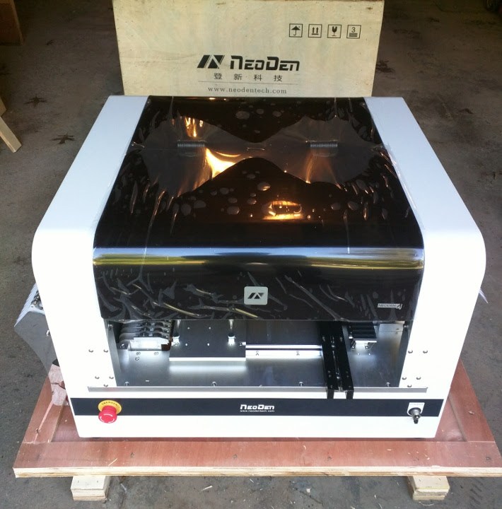
Recently NeoDen released a new model called NeoDen 4 — it’s their first desktop model that has built-in computer vision system. The vision-based alignment makes it possible to place fine-pitched components with minimal manual work. It has four pick and place heads, which means if can simultaneously pick up to four components at a time. It can fit a lot more feeders, and can handle a variety of component types, including matrix tray components, and any special components that you can lay out in a 3D printed tray. It has a vibration feeder for components in tube packaging. Although I rarely use tube packaging, one notable exception is the CH340G USB-serial chip, which is used in almost all my products, and so far it only comes in tubes. On top of these exciting new features, the machine I ordered comes with a PCB conveyor belt that can automatically feed PCBs into the system. This is really convenient for starting a pick and place job.

img_20160916_162204img_094454

Well, a picture is worth a thousand words, and a video is worth a thousand pictures! Without further ado, here is my video review of this machine:

So far I am pretty happy with the machine. Pricing-wise, it’s surely more expensive than TM-240A, but not significantly. I paid around 9K in total, including DHL shipping and all the feeders (for TM-240A I paid 5.5K). It’s not all perfect so you’ve got to learn the quirks. For example, I learned that the component height is often quite important — without providing the proper component height, the placing may give you a lot of troubles. Also, for components that need better placement accuracy, reducing the placing speed (say, to 50%) helps a lot to improve the accuracy and reliability.

Overall the machine operation is fairly intuitive, and it works in a predictable manner, much better than some of the comparable products I’ve seen on the market. No matter how powerful the machine is, you can’t afford to spend forever learning how to use it. It took me just two days of looking through the user manual, video tutorials, and doing my own trial and error to learn to successfully produce the first board using this machine. I would say it’s pretty good.

Disclaimer
I am not associated with NeoDen in any way. I am just a standard user. Please do NOT contact me for purchasing or sales questions. Go to their company website (www.neodentech.com) for details.


EagleCAD ULP Script

One difficulty I had initially was how to export a PCB design to a format acceptable by the machine. Without this I would have to manually locate the x-y coordinates of each component using the down-facing camera, which would be a huge pain. The user manual and video tutorial had no descriptions about the format of the spreadsheet. After banging my head on the wall for a while, I found one example spreadsheet somewhere in the flash drive that came with the machine, and that seems to work. Then I went ahead and modified an existing EagleCAD script (designed for TM-240A) to match the example spreadsheet. The script can be downloaded from the link below. Please take a look at the README file as it explains how to use the script.


OpenSprinkler Pi Laser Cut Enclosure

For a long time, OpenSprinkler Pi (OSPi) has been using the OpenSprinkler injection molded enclosure. While this has worked fine, the enclosure is not particularly designed for OSPi, leaving some cutouts not aligned with Raspberry Pi. Recently I have started learning to design enclosures using laser cut acrylic pieces. This is a great way to design fully customized enclosures for circuits. Today the first batch of laser cut enclosures for OSPi has arrived, and we will be shipping these with OSPi kit right away.

Here is a picture of the enclosure pieces and screw bag:
img_1262

And here is a picture of the enclosure after it’s fully assembled. After removing all the protective papers from the acrylic pieces, it produces a fully transparent look of OSPi, which is pretty cool.
img_1261

It’s not necessary to remove all the protective papers. I would recommend leaving the papers on except the top panel. This way it gives a kind of wooden texture of the enclosure, and adds more protection to the enclosure.

Below is an instructional video that walks you through the assembly steps:

I will make a separate post shortly that explains how to automate the design of such laser cut enclosures.

Learning Electronics — 2. Fun with Crystal Radio and Extensions

As a kid I was fascinated by the Crystal Radio — the simplest radio that requires no battery or power source. Learning about crystal radio is what got me into electronics in the first place. There are plenty of tutorials you can find online about how to build your own. In this blog post I describe a basic version of the crystal radio, and a couple of simple extensions using modern techniques to improve its quality (although these extended versions all require battery). I won’t talk much about the principles, but instead will focus on making it easily reproducible and a fun weekend project.

(By the way, this is the second of the ‘Learning Electronics’ series. The first one was about the Astable Multivibrator circuit and was posted five years ago… Alas, time flies!)

The Basic Version
The basic version of crystal radio that I learned as a kid consists of just 7 components as shown below. In fact, the resistor R is optional, making it only 6 components. There is an inductor L, variable capacitor C, diode D, high-impedance earphone (you can use a piezo disc), and antenna and ground. The amazing thing about this circuit is that it has no battery or power source, as the radio signal directly drives the earphone.

crystalradio_basiccrystalradio_lccrystalradio_pd

Because radio signals are very weak, to make it successful, there are several key ingredients:

crystalradio_gnd

  • Earphone: you have to use a high-impedance earphone — the typical earbud has very low impedance (less than 32 ohm), which is too heavy a load to drive with direct radio signals. The easiest solution is to use a piezo disc, which has very high impedance and is very cheap. You can then use a thick paper (or better, 3D printing!) to make a cone cover so that you can easily insert it into your ear.
  • Diode D: use a diode with small forward drop voltage. The classic choice is a Germanium diode, such as 1N34A or 1N60. However, Germanium diodes are difficult to source these days. So if you can’t find a Germanium diode, a small Schottky diode like the common 1N5817 would also work. Again, the point is to use a diode with the smallest forward drop voltage possible.
  • Antenna and Ground: a good antenna is critical for crystal radio. The antenna should be set up outdoors if possible. I implemented mine using a long single stranded wire and ran it around the perimeter of my porch. It worked quite well. As for ground, I just inserted a wire into the ground hole of a 3-prong wall socket. Be careful: make sure it stays reliably in the ground hole. If the wire touches the hot socket, it will be extremely dangerous!
  • Tuning Circuit: inductor L and variable capacitor C form the tuning circuit. These are pretty easy to find in an old radio or a DIY radio kit (as shown in the picture above). A lot of the inductor coils you can find have both a primary coil and secondary coil. You can use just the primary coil, or connect the primary and secondary in series. Similarly, a lot of the variable capacitors have two sections. You can use either section, but to help increase the frequency range of reception, you can connect the two sections in parallel.

The best time to try the crystal radio is probably at night, when there is less electro-magnetic interference in the air and the ambient noise is low. Slowly turn the dial on the variable capacitor and listen carefully. If there is a strong local AM station, you should be able to hear it. If you can’t hear anything, don’t worry, read on and you can find how to use a simple audio amplifier module to help you hear weak channels.


LM386 Audio Amplifier Module
The first time I heard something from the crystal radio, it was really exciting. But the volume is just too small to keep enjoying it. After a bit of Googling, I found a simple audio amplifier chip LM386, which can easily amplify the radio signal to be played on a speaker. It’s pretty easy to build the circuit myself, but there are ready-made LM386 modules that you can find on eBay and Amazon, for only a couple of bucks. So I bought one. Soldered a few wires, connected a standard 8 ohm speaker, and plugged in a 9V battery: wow, now you can hear the radios loud and clear, much better! Below is the updated schematic and a picture showing the wiring:

crystalradio_lm386crystalradio_lm386pic

crystalradio_lm386closeup


TA7642 Radio IC
With LM386, the sound is loud and clear. But there is still one problem: the antenna and ground wires are very cumbersome, and make the circuit non-portable. I did some more Googling, and found a simple radio IC called TA7642 that can amplify and detect AM signal, eliminating the antenna and ground wires. TA7642 is a 3-terminal IC shaped like a transistor. It’s quite simple to use and can work at a voltage as low as 1.2V, which is ideal for battery power. You can buy it from eBay or Amazon. I got mine from the Chinese website Taobao, for a jaw-dropping price of 20 Chinese cents (about 3 US cents). Below is a typical circuit of TA7642 that works with high-impedance earphone. It is powered by a single AA battery:

ta7642_simple

This time the antenna and ground wires are gone, so the circuit becomes portable. To hear the sound through a speaker, you can again use the LM386 audio amplifier. Because LM386 requires at least 5V, it won’t work with a single AA battery. But it’s common to use a 9V battery to power the whole circuit, and two diodes in series to create the 1.5V operating voltage that TA7642 needs.

I implemented the circuit using an electronic experiment kit, which has most of the components I needed. I can easily make a custom PCB to fit everything in a small enclosure. At night I can hear about 3 to 4 stations. Cool!
ta7642_pic

DIY Radio Kit: so after I built the circuit, I discovered that Elenco sells a $15 DIY Radio Kit that is essentially the same circuit as I learned above (i.e. TA7642 + LM386). So if you want a kit that includes all the components, this is a very decently priced kit to buy.

Along my search, I also found some DIY Radio Kits from Taobao, like this six-transistor radio, and seven-transistor radio. For less than $2, these kits include PCB, all components, speaker, and even an enclosure! What a crazy price!


It was a lot of fun to re-live my childhood passion by learning to build the crystal radio again, with some modern touches. The experiments above are quite easy to reproduce, and hopefully they provide inspirations for you to try them out as well.