Announcing OpenSprinkler Pi v1.2

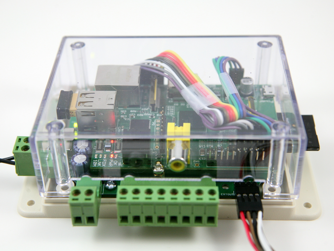
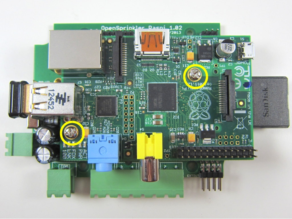
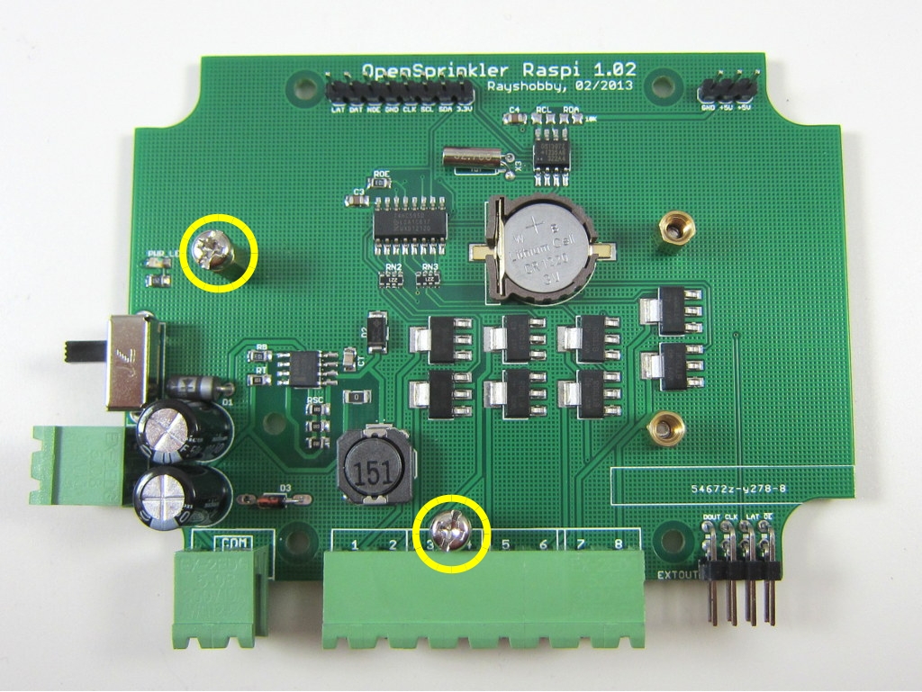
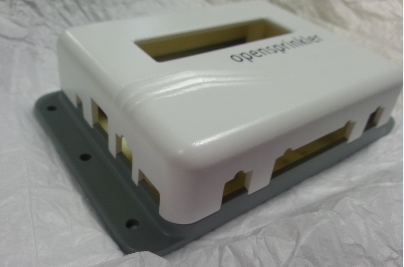
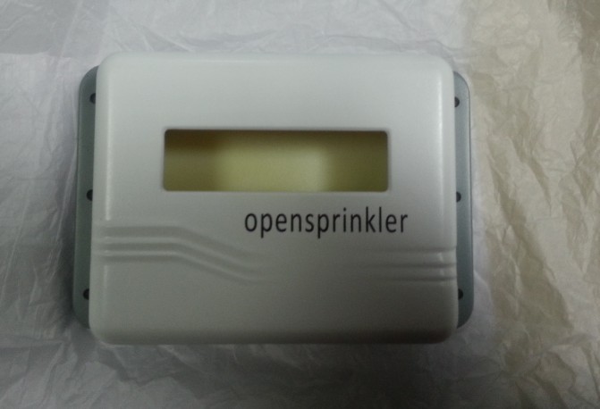
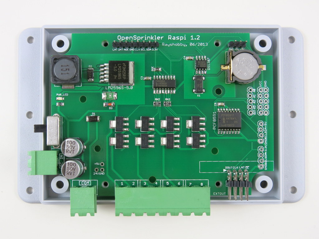
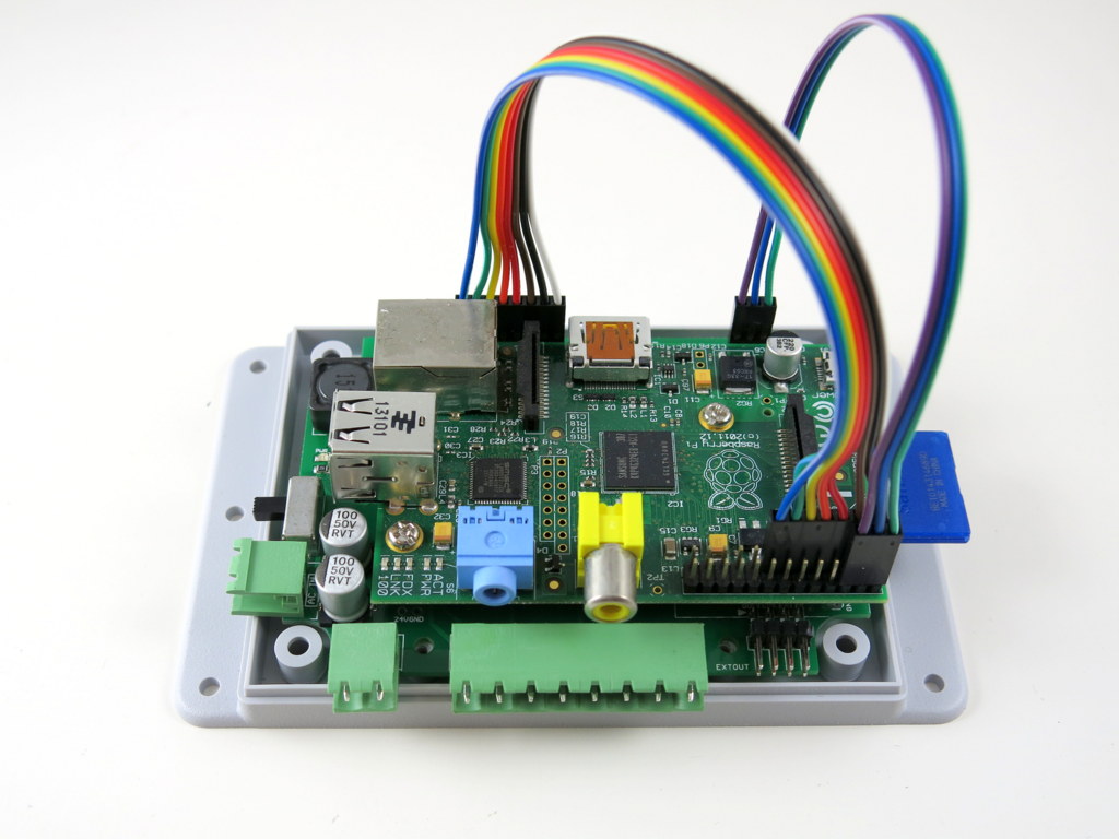
Hi, this is a new product post for OpenSprinkler Pi (OSPi) v1.2. Since its original release, OSPi has become a very popular product. This version is a minor revision. The main change compared to version 1.1 is the addition of a PCF8591T 8-bit A/D D/A converter, which provides four independent 8-bit analog input pins, and one 8-bit analog output pin. The reason this has been added is that Raspberry Pi (RPi)’s GPIO pins do not have built-in ADC capability. In order to interface with analog sensors (such as soil moisture sensor, light sensor etc.), you would need an ADC unit. The addition of the PCF8591T chip allows OSPi to provide on-board analog inputs as well as output. This makes it more convenient for your prototyping need. Other than this, the rest of the circuit is pretty much the same as before, with 24V AC to 5V DC switching regulator (based on LM2596S), DS1307 RTC and backup battery, 74HC595 shift register and triacs. Here are two pictures of the OSPi v1.2 board:

IMG_0004IMG_0008

If you Google ‘RPi ADC’ you will find plenty of choices of ADC modules and tutorials on how to get them to work with RPi. Why did I pick PCF8591T? There are several reasons. First, it’s low-cost: volume pricing is just a couple of dollars per piece. Second, it provides four independent A/D channels, and one D/A channel. This means you can use one chip to interface with 4 different analog sensors, and additionally you can get one channel of analog output. According to the datasheet, the analog output is implemented with resistor divider chain, which is sometimes a better choice than PWM. Also, it uses I2C interface, so it doesn’t require any extra GPIO pins from RPi. Overall it’s a very attractive choice. The main downside is that it’s only 8-bit. This means the analog input value is on a resolution of 0 to 255, same with analog output. A lot of the other chips provide at least 10 bits of precision. But I figured that 8-bit is sufficient in many cases, so I settled with this choice.

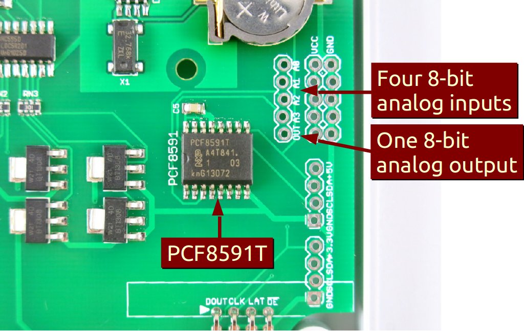
The chip, together with analog pinouts, are located on the right-hand side of the board:
IMG_0006_annotated

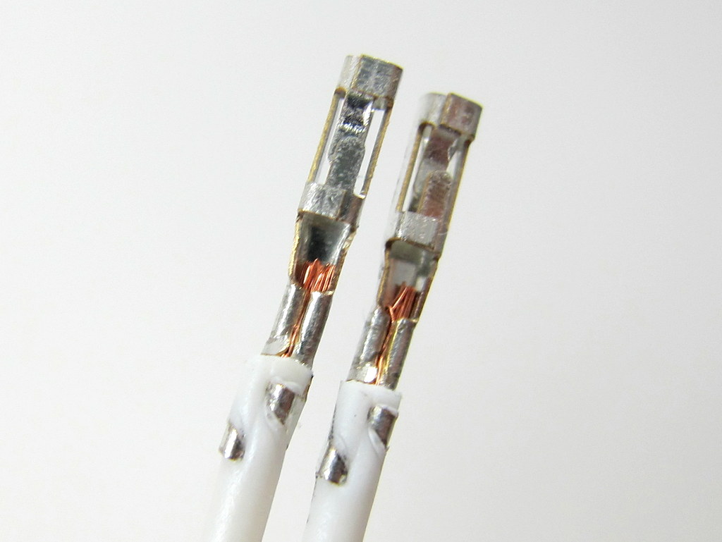
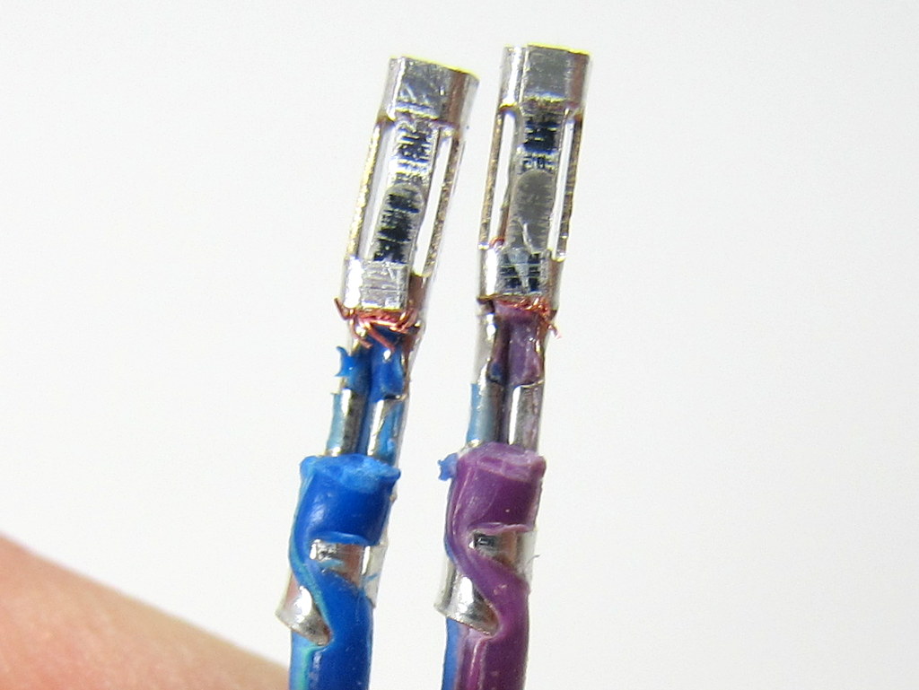
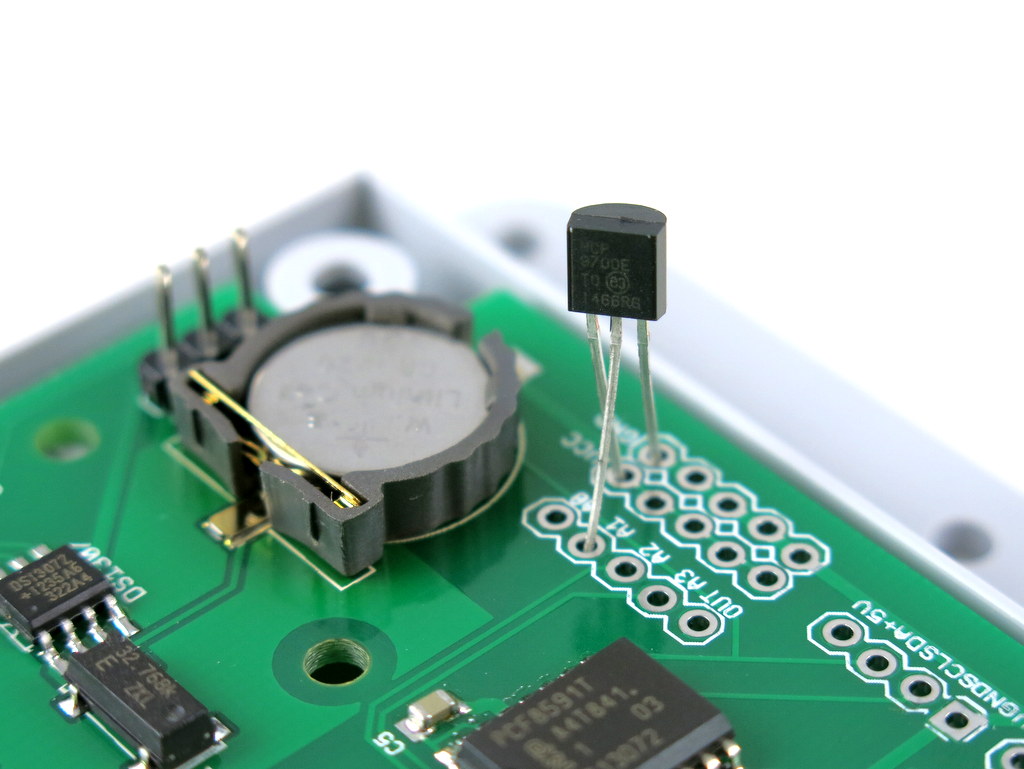
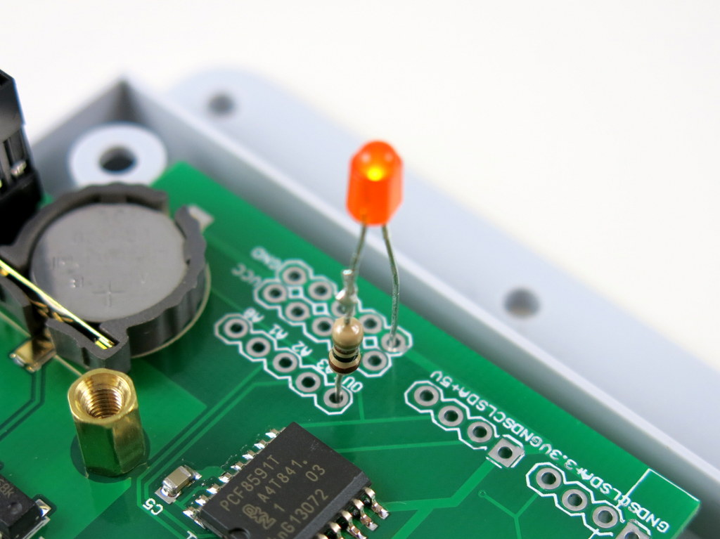
For convenience, I’ve also provided a separate pair of VCC and GND pinouts for each analog channel. The picture on the left below is an example of plugging in a MCP9700 temperature sensor directly to the pinouts; and the picture on the right below shows an LED (with current limiting resistor) plugged into the analog output channel, to allow programmable control of the LED brightness.

IMG_0005IMG_0009

Suppose this gets you interested, the next question is how to program RPi to talk to the ADC chip? Fortunately there are plenty of tutorials online. In particular, I found the following posts very useful:

If you are confused and just want a quick demo. Here is a short tutorial to get you started.

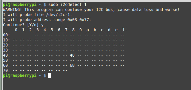
First, run sudo i2cdetect 1 to check if the PCF8591T chip is detected. (Note, if you own RPi rev. 1 you should run sudo i2cdetect 0 instead). You should then see a printout like the following. This shows it has detected two I2C devices, one is at address 0x68 (that’s the DS1307 RTC), and one 0x48 (this is PCF8591T).
pcf8591t_i2cdetect

Next, you can use the i2cget command to read analog values from a particular channel. For example, run
sudo i2cget -y 1 0x48
repeatedly to sample the analog value from channel 0 (pin A0). To change to channel 1 instead, run
sudo i2cset -y 1 0x48 0x01
and then if you run sudo i2cget -y 1 0x48 that will return sampled value of channel 1, and so on.

To enable analog output, use the i2cset command. For example:
sudo i2cset -y 1 0x48 0x40 0xff
where 0xff is the 8-bit analog output value. You can change it to any value between 0x00 to 0xff to enable 256 grades of values. Since the chip is powered by 3.3V supply, that will translate to an analog output from 0V to 3.3V linearly.

The above use shell commands as an example to interface with the chip. There are also WiringPi and Python code examples which can do the same. When I get time I will write a more complete tutorial. For now, try to explore on your own 🙂

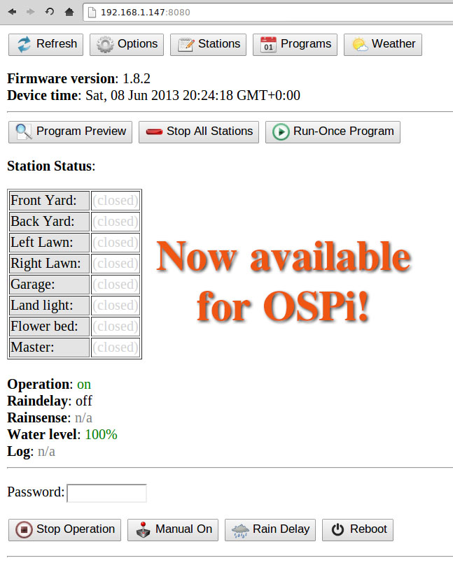
OpenSprinkler Pi v1.2 is immediately available for purchase at Rayshobby Shop, at the same old price.

OpenSprinkler Interval Program is now available for OSPi

Good news to the OpenSprinkler Pi users: the same interval program firmware that runs on the latest OpenSprinkler has now been ported to OpenSprinkler Pi! This is due entirely to the generous contributions by Dan Kimberling, who ported the OpenSprinkler’s Arduino code to Python. The code is available for download at Dan’s GitHub repository. Instructions can be found at the Rayshobby Wiki page:

(Note: the grayed-out instructions below are obsolete and are only kept here for archiving purpose. Please follow the instructions on the Wiki page above for how to install and use the latest software. Thanks.)


For anyone who is unfamiliar with RPi, here are some basic instructions to follow:

  • First, ssh to your RPi (or connect your RPi to a monitor and open a Terminal), and type in run the following command in one single line(i.e. the ‘wget’ command, space, and the very long link): wget https://github.com/rayshobby/opensprinkler/raw/master/OpenSprinkler%20Pi/software/demos/interval_program/ospi.tar.gz
  • Next, run tar zvxf ospi.tar.gz. This will unzip the file to a subfolder named OSPi in your current directory.
  • Now, cd OSPi, and then run sudo python ospi.py (note that you will need to type in your RPi account password). This will start the web server.
  • Open a browser on your computer or any device that’s connected to the same network as your RPi, and type in your RPi’s IP address, followed by colon, and the default port number 8080. For example, for my RPi, the address is http://192.168.1.147:8080. You should now see the homepage of the interval program demo. Note that the port number can be changed to other values, in which case you need to check the source files to figure out how to make the change (or post a message on the forum and I am sure someone will help you).


interval_program_ospiospi_header

This demo program is the same as OpenSprinkler 1.8.2 firmware. So you can follow the OpenSprinkler Online User Manual for usage instructions. I believe all features of the firmware are supported. Keep in mind that this is still work in progress, so there are glitches and bugs that will be ironed out over time. If you are a developer, you are welcome to improve the code or help fixing bugs. The backbone of the software is based on web.py, a popular and easy-to-use web framework for Python.

Also keep in mind that if you have RPi rev. 2 (which is the current model), you need to open ospi.py and edit a port number. Details can be found in the README.txt file. P.S., it’s generally a good idea to read the README.txt first before you start doing anything.

These will be the basics to get you started. If you have any questions, feel free to post a message on the forum.

Finally, a big thank-you again to Dan Kimberling for his time and efforts in making this available to the public. This is an example of the true spirit of open-source development and community support. I am very excited to see additional user contributions to the OpenSprinkler Pi project!

Annoying ribbon cable problem with recent orders of OpenSprinkler Pi

Hi, this is an alert to users who recently ordered OpenSprinkler Pi: we’ve found an annoying problem with the 8-pin ribbon / rainbow cable that comes with the package. Apparently many of the cables have disconnected crimp wires, causing the OSPi to not respond to RPi, or even worse, causing all stations to turn on at the same time. I estimated that there are potentially up to 60 orders that might be affected. We’ve proactively taken actions to send a replacement cable to everyone who ordered OSPi recently (within the last 2 weeks). If you are seeing an issue of your OSPi not responding to RPi, try to use a multimeter to measure the connection on each of the 8 wires of the cable. If any wire is not connected, please email to [email protected] and we will send you a replacement cable right away.

Here is a closer look at the cause of the problem. When I take the wire out of the crimp connector, you can clearly see that the good ones (shown on the left below) have metal wires tightly secured by the crimps, while the bad ones (shown on the right below) have the metal wires cut from the cable, resulting in disconnection. This is probably due to a defective wire stripper or crimp tool, or incorrect operation that causes the metal wires to be completely cut through. In any case, I’ve informed the supplier and complained about the the quality, and will never order from them again.

IMG_2963IMG_2965

So the lesson to learn here is that when testing OSPi, we really should use the individual cable that goes with each board, instead of using a common testing cable. Another lesson to learn is to never overlook any part, even something as simple as a cable!

I became aware of the cable issue when a couple of users reported that their OSPi did not work. This is very puzzling because every single board has been tested and verified, so the chance of DOA is very small. I’ve asked two of them to send their boards back to me, and after testing, I couldn’t find any obvious problem — the board works fine, and all demo programs work fine. However, until yesterday, I have apparently overlooked the problem with the cable: when testing, we have always used a common testing cable, instead of the user’s cable. Partly it’s because I never thought the cable would have any problem at all. Now I’ve learned a lesson, and it’s a good lesson to learn!

OpenSprinkler Pi v1.02 Released

I’ve made a minor update to OpenSprinkler Pi (OSPi), and the new version v1.02 has improved design of the separation pillars in order to make use of the screw holes available on Raspberry Pi rev. 2. See the picture below:
IMG_2669_a
This way, the Raspberry Pi rev. 2 can be more securely attached to the OSPi even with just two screws.

If you own a Raspberry Pi rev. 1 instead, don’t worry, you can still attach it to OSPi using the two edge screws (see the picture on the right below), in the same way as the original OSPi. To do so, you will need to move one of the separation pillars. See the picture on the left below (sorry, the arrow is pointing in the reverse direction).

IMG_2670_aIMG_2666_a

So in sum, the updated version OSPi v1.02 allows you to make better use of the screws holes available on RPi rev. 2 while still being compatible with RPi rev. 1.

Custom OpenSprinkler Enclosure using Injection Modeling

As mentioned in a previous post, I have been working with SeeedStudios to design a custom OpenSprinkler enclosure. Thus far I have been using an off-the-shelf Serpac WM-032C clear plastic enclosure, and I have Electronic Precepts to machine the cutouts. It was a good start and really easy to design, but the cost can quickly add up as I order more from them. Over time, it’s make more and more sense to design a custom enclosure using injection molding, in order to reduce the per unit cost.

The initial design has been finalized and a 3D printed prototype is on its way to me. I am very excited because this will be the first injection-molded OpenSprinkler enclosure! It’s a pretty heavy one-time cost (the mold costs about $5,000 to make), but it’s fun and I think it’s worth the investment. I am supposed to receive the prototype today, but a snow prevented DHL from delivering today. So I have to look forward to Monday. But below I attached some pictures Seeed sent me. They are enough to enjoy for a while 🙂 More pictures will come after I receive it on Monday.

opensprinkler 1opensprinkler 2

opensprinkler 3opensprinkler 4

OpenSprinkler Pi Back in Stock

OpenSprinkler Pi (OSPi) v1.0 is back in stock and available for shipping now. The kit includes one assembled and tested OSPi board, separation pillars, terminal blocks, 8-pin and 3-pin connection cables, and optional enclosure. You need to provide your own Raspberry Pi, and 24VAC sprinkler transformer. The board controls 8 zones, and can connect to standard OpenSprinkler zone expansion board to enable additional zones. Grab it now before it goes out of stock again!

IMG_2416

I would really like to give a big thumb-up to smart-prototyping.com. This is the first time I ordered PCBs from them (I got the link from dangerousprototypes.com), and I wasn’t sure what to expect. The order was placed on Feb 26 right after the initial batch of OSPi sold out. I selected DHL shipping (about $30) since I need it to be quick. On Feb 28 I decided to place a smaller order for the new zone expansion board prototype PCB, and I selected economy air shipping (about $4) since I don’t care how fast it comes. Then on March 5, exactly one week after placing first order, I noticed it got shipped out. I happily received the package on March 7. This is a total turn around time (from ordering to delivery) of only 9 days! What’s more surprising is that when I opened the package, I found my second order is also included. They must have figured out that since both orders are going to the same address, and both were ready upon shipping of the first order, why not put them together and use the fastest shipping. Clever! I am really impressed by their processing speed and the super-fast shipping time. Also, the PCB quality is very good, and their price is even cheaper than SeeedStudios. Highly recommended, and will definitely order from them again!

IMG_2415

OpenSprinkler Pi (OSPi) 1.0 — a sprinkler / irrigation extension board for Raspberry Pi


Hi, I am glad to announce the arrival of OpenSprinkler Pi (OSPi) 1.0 — a sprinkler or irrigation extension board for Raspberry Pi that provides direct access and control of sprinkler valves. This post serves as a quick introduction to the hardware and software setups. A more dedicated webpage will be available soon. First off, a picture of the board:

ospi_header

and a video introduction:


Background

Since the beginning of Raspi, there have been many published DIY projects on how to use Raspi for home automation need. I bought a Raspi a few months ago, and have been quite happy with it since then, but I at that point I had not thought about designing an OpenSprinkler extension board for it. The idea of OSPi first came when I noticed that several OpenSprinkler users were setting up Raspi to work with OpenSprinkler. There are many good reasons to do so, for example, to enable logging, to customize the default Javascript files, and to allow more advanced features such as weather-based and learning-based control. At one point I started thinking: wouldn’t it be nice to design an extension board for Raspi, so that it can directly talk to sprinkler valves through the GPIO pins, without an additional layer of microcontorller and Ethernet controller? This has been on my todo list for quite a while, until one day I was playing with Raspi, and I suddenly that the I can actually fit a Raspi inside the existing OpenSprinkler enclosure. As soon as I figured this out, I couldn’t resist ordering a small batch of prototype PCBs right away.


The content below has been updated and moved to a dedicated product page for OSPi at http://pi.opensprinkler.com.


My First Raspberry Pi

Look at what came in the mail today:

It’s my first Raspberry Pi (Raspi)! I know I should have got it much earlier, but I was not fond of being put on a waitlist. Apparently I should have kept better track of it: I was checking some stuff on Newark.com the other day and accidentally noticed that Raspi is in stock. Without any hesitation I immediately placed an order. Three days later, it’s here!

First impression:
Gosh, it’s small! It’s the size of a credit card, and the build quality is pretty sold. It’s powerful eough to run a Linux system with X server, and it even has HDMI output so I can directly use it with my high-resolution LCD. The setup was quite easy. The machine boots from an external SD card. All I did was to grab a 4GB SD card, follow the instructions here to flash the default raspbian image onto the card, and insert it to the SD card slot on board. Then I used a micro-USB cable to power it up. I also digged out an old 3.5 inch LCD screen from Dx.com and it works perfectly with Raspi (though the resolution is low, hence it’s not really good for reading, but good for showing 🙂

Standard keyboard and mouse should work well out of box. This version (model B) of Raspi has two built-in USB ports. Of course you can use an USB hub to extend the ports. It doesn’t have a WiFi chip on board but it does have a Ethernet jack. I plugged in a NetGear WNCE2001 WiFi adapter and instantly I have WiFi connection. It also works with a variety of USB WiFi dongles, so it’s really convenient.

One of the biggest selling points of Raspi is of course its price: this model B is just $35 before tax and shipping (keep in mind that even an Arduino board, which has a must simpler microcontroller, would cost almost $30). This is totally impressive, especially considering we have to factor in reseller margins on top of the manufacturing cost. I don’t what’s the profit margin, but perhaps it is consistent with a recent article that discusses how you can’t make money any more on hardware, instead, it’s the software and service that keep consumers to buy in.

Anyways, I am glad I finally got one. There is a lot of stuff I am excited to experiment with using Raspi, and I am sure I will come up with some itneresting project ideas along the way. A thumb up for Raspi!