First Impression on the ESP8266 Serial-to-WiFi Module


Check my new blog post on the ESP8266 Toy


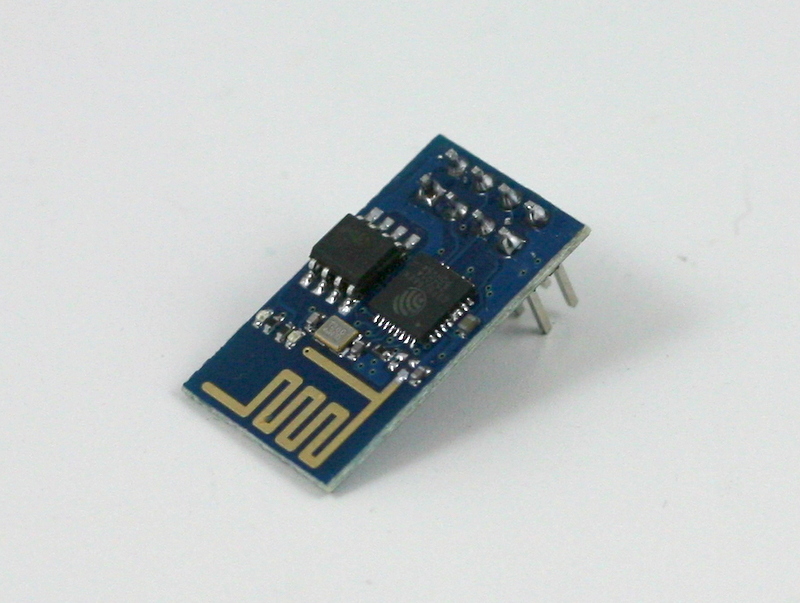
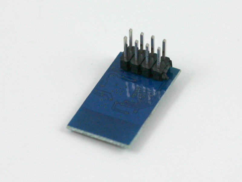
Continuing from my previous blog post about Hi-Link HLK-RM04 module, I have finally received the ESP8266 Serial-to-WiFi module that I’ve been waiting for. As I said previously, with the popularity of IoT devices, there is an increasing demand for low-cost and easy-to-use WiFi modules. ESP8266 is a new player in this field: it’s tiny (25mm x 15mm), with simple pin connections (standard 2×4 pin headers), and best of all, it’s extremely cheap, less than US$3 from Taobao.com!

IMG_3188IMG_3189IMG_3190

What is Serial-to-WiFi? Simply put, it means using serial TX/RX to send and receive Ethernet buffers, and similarly, using serial commands to query and change configurations of the WiFi module. This is quite convenient as it only requires two wires (TX/RX) to communicate between a microcontroller and WiFi, but more importantly, it offloads WiFi-related tasks to the module, allowing the microcontroller code to be very light-weighted.

There are already a lot of excitements and resources you can find online about ESP8266. I’ve included a few links below:

These are great resources to reference if you need help working with ESP8266. Below I document my own experience. I’ve also bought a few extra and put them available on the Rayshobby Shop for anyone who is interested in buying the module and don’t want to wait for the long shipping time from China πŸ™‚


Check my new blog post on the ESP8266 Toy


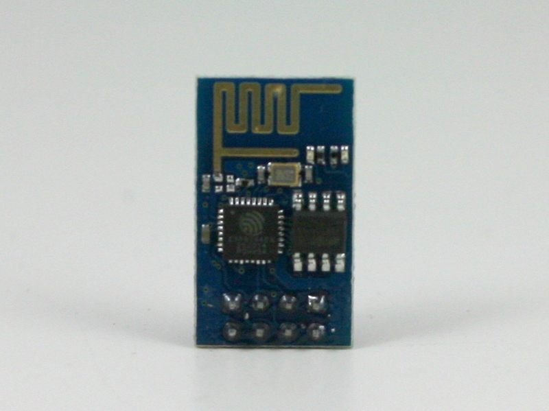
Pin Connections. ESP8266 is sold in several different versions. The one I received is the version with 2×4 male pin headers, and PCB antenna. In terms of the form factor, it looks a lot like the nRF24L01 2.4G RF transceiver. Here is a diagram of the pins:
ESP8266_pinout
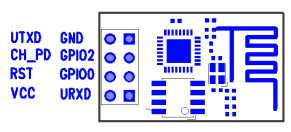
Connect the top two pins (UTXD, GND) and bottom two pins (VCC, URXD) to the RXD, GND, VCC, TXD pins of a microcontroller. Note that VCC must be no more than 3.6V. The middle four pins are should be pulled up to VCC for normal operation. However, if you need to upgrade the firmware of the module, you need to pull the GPIO0 pin to ground — that way upon booting ESP8266 will wait for a new firmware to be uploaded through serial. This is how you can upgrade the firmware in the future.

A few quick notes for connection:

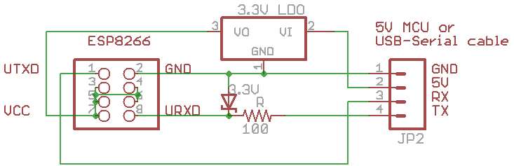
  • The typical operating voltage is 3.3V (acceptable range is 1.7V to 3.6V). As the module can draw up to 200 to 300mA peak power, make sure the power supply can deliver at least 300mA. For example, the 3.3V line from a USB-serial cable would be barely sufficient, in that case it’s better to use a LDO to derive 3.3V from the 5V line.
  • When using the module with a 5V microcontroller, such as a standard Arduino, make sure to use a level shifter on the URXD pin — a simple resistor-zener level shifter is sufficient. Again, this is to prevent over-voltage.

A schematic will make it clear. See below. In my case, I soldered the components and a matching female 2×4 pin header to a perf-board. This way I can easily plug in and unplug ESP8266. Again, if you are using a 3.3V microcontroller, you can do away with the LDO and zener diode.

esp8266_connIMG_3194

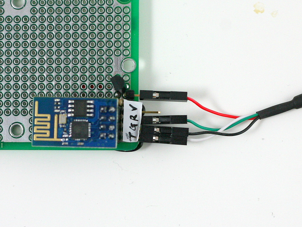
Experiments using a USB-Serial Cable. Before connecting to a microcontroller, it’s a good idea to use a USB-Serial cable (such as the inexpensive PL2303 USB-serial converter) to check out the basic functions of the module. Connect the PL2303 cable with ESP8266 according to the schematic above. Then open a serial monitor (such as gtkterms in Linux and putty in Windows) with 11520 baud rate (my ESP8266 seems to be set to 115200 bard rate; earlier versions use 57600). Then you can use a list of AT commands to talk to ESP8266. The AT commands are pretty well documented on this page. Below are some example input (shown in bold font) and output that show how to reset the module, list available WiFi networks, check the WiFi network it’s connected to, list IP address, and firmware version etc.


AT
OK
AT+RST
OK
ets Jan 8 2013,rst cause:4, boot mode:(3,6)
wdt reset
... ...
chksum 0x46
csum 0x46
ready
AT+CWLAP
+CWLAP:(0,"",0)
+CWLAP:(3,"freefly",-49)
OK
AT+CWJAP?
+CWJAP:"freefly"
OK
AT+CIFSR
192.168.1.130
AT+GMR
00150900
OK

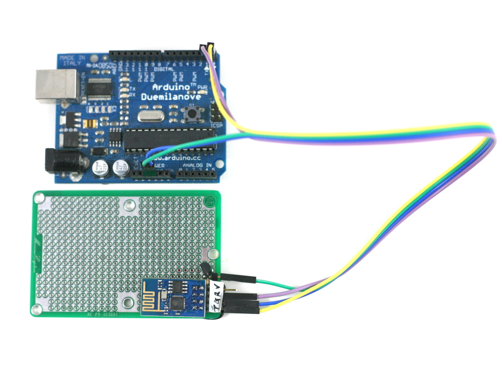
A Simple Demo using Arduino.
Next, I connected ESP8266 to an Arduino. Because Arduino is already using the TX/RX pins for bootloader, make sure to unplug ESP8266 while flashing the Arduino, otherwise you may not be able to upload a sketch successfully. Also, you can’t use TX/RX for printing debugging information, since ESP8266 will be using them to communicate with Arduino. Instead, you can use another pair of pins (e.g. D7 and D8) as software serial pins, and use a PL2303 serial cable to monitor the output. This will help print debugging information.

I’ve also experimented with using software serial to communicate with ESP8266, but that has failed — ESP8266 requires 115200 baud rate, and that’s a little beyond the capability of software serial. So you have to stick with the hardware TX/RX pins.

(Update: the code has been revised on Dec 14, 2014 to improve robustness, particularly for some of the latest ESP8266 firmwares. Right now there is still an issue that if the browser is closed before the transfer is completed, it may leave ESP8266 in the notorious ‘busy s’ mode, the only solution to which is to do a hard reset. If using the module in real products, make sure you have a way to use a microcontroller pin to reset the power of the module, thus providing a way to hard reset the module. It looks like future firmwares may be able to address this in software.)

The demo program first configures ESP8266 to log on to your WiFi network (SSID and password are given as macro defines at the beginning), then it sets ESP8266 as HTTP server with port number 8080, and it listens to incoming request. If you open a browser and type in http://x.x.x.x:8080 where x.x.x.x is the module’s IP address (printed to soft serial pins), you will see the output which is a list of analog pin values, and the page refreshes every 5 seconds. So this is a basic Hello World example that shows how ESP8266 can be configured as an IoT server, responding to incoming requests.

IMG_3193

Challenges. While my initial experiments with ESP8266 have been quite successful, I’ve also encountered minor issues that took me a while to figure out. For example, while the AT commands are well documented, they don’t seem extremely consistent — some commands allow question marks at the end, some don’t. I also see variations of the returned values from running the AT commands: sometimes there is an extra end of line character, sometimes there is none. These basically require a robust software library to handle all possible cases.

Overall I would say ESP8266 is a very promising WiFi module for IoT, particularly open-source IoT gadgets, because of its low cost, compact size, and the community development. It seems the manufacturer has also open source the firmware code, and thus the minor issues can probably be easily fixed through a firmware upgrade.

We have a small number of ESP8266 modules available in stock, and will continue to offer them if there are sufficient interests. Thanks!


Check my new blog post on the ESP8266 Toy


Announcing AASaver 2.1 — a versatile boost converter for AA/AAA batteries

This is a quick update that AASaver has been upgraded to version 2.1. It inherits all the capabilities of version 2.0, including built-in 5V voltage booster, flashlight LEDs, breadboard power pin headers, USB port (for charging USB devices), LiPo charger (with adjustable charging current). On top of those, version 2.1 adds a 3.3V LDO and a switch you can use to choose between 5V or 3.3V output voltage. This has been the main requested feature that was missing on version 2.0. Using an LDO (instead of changing the feedback resistors) has the advantages that the voltage booster and USB port always output 5V, while the 3.3V output is only effective on the LEDs and the breadboard pin headers. Here are some pictures:

IMG_0173IMG_0158IMG_0161

IMG_0162IMG_0159IMG_0171

For those who are curious what AASaver is: it’s a multi-purpose voltage booster for AA/AAA batteries. I came up with this idea initially when I was cleaning up a box of ‘dead’ AA batteries one day, and was surprised that many of them actually have pretty good output voltage, like 1.2 to 1.3V. Many AA batteries rejected from gadgets (e.g. remote controls and smoke alarms) still have plenty of juice, but these gadgets don’t have built-in booster circuit to bump the voltage up, so a lot of batteries are wasted this way. I was learning voltage booster at that point and had the idea of designing a multi-purpose circuit for AA batteries, so that I can harvest the remaining energy in ‘dead’ batteries for a variety of things, like lighting up LEDs, powering breadboard circuits, charging LiPo batteries etc. That’s how AASaver was invented. It’s not restricted to used or ‘dead’ batteries — if you plug in a fresh pair of batteries, you can also use it to charge your phone or other USB gadgets. It’s a really neat, useful, and inexpensive tool that everyone should have a few of these!

Below is the original video I made for AASaver. Keep in mind that the current version has a lot more features than shown in the video, including USB charging, LiPo charging. You can even modify it to become a solar charger.

With this new version, I’ve also prepared a more detailed User Manual, with assembly and usage instructions. We have just fulfilled an order from Micro Center so in the near future you may even find AASaver in the Micro Center retail stores πŸ™‚

Announcing OpenSprinkler Bee (OSBee) Arduino Shield v1.0

Update: check out our new standalone OpenSprinkler Bee (OSBee) 2.0 with built-in WiFi and OLED display.

Two months ago, I wrote a blog post about the preview of OpenSprinkler Bee, which is an open-source arduino-based controller for battery-operated sprinkler valves. While that’s still in the development stage, today I am glad to announce that an Arduino shield version of OpenSprinkler Bee is completed and immediately available for purchase at the Rayshobby Shop.

Update: check out our new standalone OpenSprinkler Bee (OSBee) 2.0 with built-in WiFi and OLED display.

IMG_0073IMG_0075

So what is this Arduino shield version, and how is this different from other OpenSprinkler prodcuts that we carry? Well, an Arduino shield is a circuit board that you plug into an existing Arduino — it does not have a microcontroller chip itself, but contains additional circuitry that extends the basic functionality of an Arduino. So to use the shield, you will need to provide an existing Arduino board.

How is the OpenSprinkler Bee (OSBee) different from the other OpenSprinkler products? The main difference is that OSBee is designed to work with battery-operated sprinkler valves. These valves internally use a latching solenoid, which only draws power when you open or close the valve, and does not draw power if it remains in the same state. So it’s very efficient and suitable for battery-operated controllers. The other OpenSprinkler products, such as OpenSprinkler 2.1s, DIY 2.1u, OSPi 1.4, OSBo 1.0, are all designed for 24V AC sprinkler valves, which operate on 24V AC and require a power adapter / transformer.

While OSBee shield itself does not have built-in wireless modules, you can stack it with other Arduino shields, such as RF, WiFi, Ethernet shields, to provide web connectivity. The OSBee Arduino library has one example of using the Arduino Ethernet shield with OSBee shield to create a web interface for sprinkler control.

Is there any easy way to tell latching solenoid valves from 24V AC valves? Yes. Latching solenoid valves usually come with a special plug, and the two wires are usually colored differently because the solenoid has polarity. 24V AC valves usually come with just two wires colored in the same way (because AC voltage has no polarity). Here are some examples of latching solenoid valves. Note the special plugs and/or different wire colors.

IMG_0072IMG_0078

For valves that come with stripped wires, simply attach them to the screw terminal blocks on OSBee shield. For valves with special plugs, you can cut and strip two pieces of wire (20 to 24 AWG): insert one end of the wire to the plug, and the other end to the screw terminal block.

IMG_0080IMG_0077

How to open or close the latching solenoid valve? Electrically, latching solenoid valves have quite low coil resistance (a few ohms). To open the valve, you apply a momentary positive voltage on the coil. The specific voltage depends on the valve specification, but it typically varies between 9V to 22V. To close the valve, just reverse the voltage polarity. The important thing to keep in mind is that the voltage is applied as a pulse — usually 25 to 100 milliseconds. Because the coil resistance is so low, the instantaneous current is very high, up to a few amps. So you can’t apply the voltage continuously (or it will smoke the coil or the power supply!) In addition, it’s better to first build up the voltage into a capacitor, and then dump the charge to the valve from the capaictor.

How to generate such a high voltage from Arduino’s 5V or 3.3V pin? It’s by using a neat circuitry called ‘boost converter‘. The Wikipedia has plenty of information about how it works, but the basic principle is to use a MOSFET switch, an inductor, a diode, and a PWM signal to build up the charge into a capacitor. This way you can generate a high voltage from a low-voltage source such as AA batteries.

How to apply a voltage in both polarities? This is by using another neat circuitry called ‘H-Bridge‘. The H-Bridge is made of four MOSFET switches. By closing the pair of switches in each diagonal direction, you can apply voltage in either positive or negative polarity. Because you also need a state where no voltage is applied on the solenoid, that’s three states in total and hence two microcontroller pins are required to produce three states. Wait, why not directly use two microcontroller pins to apply the voltage? Well, microcontroller pins can neither handle high voltage nor provide high current, so you need MOSFETs to help switch high voltage and high current using only logic signals from the microcontroller.

With all the technical concepts explained, here is the diagram of the various components on the OSBee Sheild:
osbee_shield_diagram

The shield can switch 4 independent valves / zones. The boosting voltage is software adjustable — anywhere from 9V to 24V. An Arduino library with three demo programs are provided in the OSBee Github repository. For details, please refer to:

OSBee Shield v1.0 is now available for purchase at the Rayshobby Shop. Thanks!

Announcing OpenSprinkler Zone Expansion Board v2.0 (16 stations)

A new day, a new post. Today’s post is about the new OpenSprinkler Zone Expansion Board v2.0, with injection-molded enclosure and 16-station capability. The injection-molded enclosure provides a coherent look with the OpenSprinkler main controller; and the 16-station capability adds twice as many stations as before, without taking extra space.

IMG_3135IMG_3136IMG_3137IMG_3139

As I briefly talked about in a previous post, this new version 2.0 is only slightly larger than the previous version 1.1, but can handle twice as many stations. You can think of it as basically two 1.1 boards (8 stations) squeezed together onto a single board that’s roughly the same size as before. What made this possible is a clever design that makes use of the same four support pillars to both attach the top and bottom pieces together, as well as secure the PCB inside the enclosure. This saves some space normally reserved for the PCB screws. The design was proposed by Xavier at SeeedStudio — the principal industrial designer for the project — and it follows the same design adopted for the OpenSprinkler enclosure.

Also, version 2.0 has included per-station bidirectional transient voltage suppressor (TVS) for added electric protection. These are essentially diodes can clamp the voltage if it exceeds a threshold in either direction. This can reduce the chance that a high transient voltage or lightening damages the circuit or the sprinkler solenoid.

IMG_3140IMG_3141

In terms of usage, version 2.0 is the same as 1.1. It works for all of OpenSprinkler, OSPi and OSBo. Use the 2×4 extension cable to link the OUT port of the main controller to the IN port of the expansion board. Additional expansion boards can be daisy-chained in the same way — by following the OUT -> IN links. Because 2.0 and 1.1 have the same cable wiring, they can be mixed and used together.

The firmware currently does not automatically detect the number of stations. So you need to keep in mind that each 2.0 counts as 2 expansion boards (2x 8) in the option settings.

Because of the difficulty in stocking both versions, we have discontinued 1.1 and are only offering 2.0 now. Price-wise, it is a little more expensive than 1.1. So if you only need 8 extra stations, sorry, you have to pay the extra to get 2.0. But if you need a larger number of extra stations, this is a great deal because it’s considerably cheaper and saves a lot of space too.

OpenSprinkler Zone Expansion Board v2.0 is available for purchase at the Rayshobby Shop. We offer bundled discount if you are buying it together with any OpenSprinkler main controller, including OpenSprinkler v2.1s, DIY v2.1u, OSPi and OSBo. Be sure to check the “Add Zone Expansion Board Options” when you purchase. Thank you!

Funky Design of the New OpenSprinkler Pi (OSPi) v1.4

Curious what the next version of OpenSprinkler Pi (OSPi) is going to look like? Here is a sneakpeak preview of version 1.4:

IMG_3118IMG_3125

Wait a minute, what is this strange looking board?! And the Pi is installed at an angle? What’s happening here? Well, the new design is all centered around one simple goal: to fit OSPi and RPi into the existing OpenSprinkler injection-molded enclosure. There are many good reasons to do so. The first is cost reduction: the current OSPi uses the Serpac WM032 enclosure with custom cutouts. This is quite expensive to make. On the other hand, the microcontroller-based OpenSprinkler already has an injection-molded enclosure (and I paid a good amount of money for the mold!), so it makes sense to consolidate the design to use the same enclosure. This will bring down the cost quite a bit. Using the same enclosure also gives both products a consistent look. In fact, in the near future OpenSprinkler Beagle will also adopt the same enclosure, and hence all three will have the same exterior look.

Design Story

The ‘why’ part is easy to explain. But the ‘how’ part proves to a non-trivial engineering challenge. When I was first fiddling with the idea I didn’t think it was at all possible. After all, the injection-molded enclosure was made before OSPi came into place, naturally it was not designed with RPi in mind. It turns out that, due to the positions of the support pillars, the enclosure is just a little bit too narrow to fit RPi at a straight angle. Ouch! But after staring at it for a while like a geometric puzzle, I was delighted to find out that if you rotate RPi by 3 to 4 degrees, it fits perfectly! This gave me inspiration to further develop the idea. It also explains why the Pi has to be installed at an angle, as the picture at the top shows.

IMG_3132IMG_3133

In fact, by carefully positioning the Pi, the Ethernet cable can also fit, albeit through the USB cutout instead of the RJ45 cutout. It’s a bit tricky to figure out the position precisely, but I am glad that after two rounds of prototypes I finally got it right πŸ™‚

IMG_3129IMG_3130

Of course since OSPi doesn’t have buttons and LCD, some of the cutouts are useless. I am not completely sure what to do with the LCD cutout. If I leave it alone, it looks quite ugly (see picture on the left below). So my temporary solution is to just put a sticky label at the back, thus covering the big empty hole (see picture on the right below). Eventually I think it’s best to put some graphic design here. I am undecided what to put here. It shouldn’t be the OpenSprinkler logo as the enclosure already has a printed logo. If you have suggestions, please leave them in the comments section. I would greatly appreciate it!

IMG_3127IMG_3128

Next, because the injection-molded enclosure is not high enough, I cannot continue using the current design where the Pi faces up and connects to OSPi through ribbon cables. It’s necessary to flip the Pi and plug it into OSPi facing down. This will reduce the height of the overall assembly. However, there is one additional complication: the USB, Ethernet, and composite video connectors on the Pi are all quite tall, so it’s necessary to make cutouts on the OSPi PCB to allow these connectors to sink below the board. The picture on the left below shows the back of the PCB, and you can see where the connectors go through the board.

IMG_3134IMG_3120

As the Pi is now facing down, it’s not easy to access the GPIO pins directly. Therefore I’ve mapped out all the 2×13 pins on the Pi to the pinout area, seen at the top-left corner of the PCB.

The last bit of the puzzle is the SD card. Since the enclosure has very limited space, it’s not possible to fit a full-size SD card, without making a cutout on the side. So we need a low-profile SD card. There are several options, one is this microSD to SD adapter. It’s basically a microSD card slot soldered onto a PCB shaped like an SD card but half the size. This and other similar adapters are readily available online and they work reasonably well.

IMG_3122IMG_3119

While Googling ‘low-profile SD card’, I found an surprising solution that’s dead simple. In case you don’t know this already: many full-size SD cards are actually half empty. What this means is that the useful stuff (namely the chip and connectors) only take half the space, while the other half has nothing in it! As a result, you can safely cut half of the card away, thus making a low-profile SD card without any adapter. This also has the advantage of preserving the high performance of a full-size SD card (while the microSD card is considerably slower). The downside though, is that if you ever need to insert the SD card to your computer’s SD card slot, you will have to tape the other half back, so that it extends to the original length. Otherwise it will be too short to push in and pop out.

IMG_3123IMG_3124

Anyways, this is the end of the story. I admit the new funky design feels a bit forced: it’s born out of the need to re-use the injection-molded enclosure, which wasn’t designed with OSPi in mind. But I am quite excited that I figured out all the pieces of the puzzle. Eventually I may pay a sizable chunk of money to order a new mold dedicated to OSPi, but before that happens we have to stick with the existing resources πŸ™‚

The hardware components remain largely the same with version 1.3. The only difference is that the relay has been upgraded to a slightly bigger, 250V / 3A type. I am also considering adding a pin header for the nRF24L01 transceiver, to make it possible to communicate with our upcoming products such as OpenSprinkler Bee. Pending a few minor tweaks, things should be finalized within a month or two. Please leave your comments and suggestions, as this will be the last chance to influence the final design of 1.4. Thanks!

Announcing OpenSprinkler Hardware 2.1s (assembled), Firmware 2.0.4, and a GUI-based Firmware Upgrade Tool

This is an official announcement of several recent OpenSprinkler updates: the fully assembled OpenSprinkler 2.1s, a new firmware revision 2.0.4, and a GUI-based firmware update tool.


First, the hardware:

os21sIMG_3968

So what’s new in OpenSprinkler 2.1s? Here are the main updates:

  • ATmega644 mcu running at 12MHz with USBasp bootloader.
  • Added per-station transient voltage suppressor (TVS).
  • Added TVS and 2A fuse on the 24V AC line.
  • 24V AC terminal block is changed to orange-colored with 3.96mm spacing.
  • Added on-board 120V/2A mini-relay.

These pretty much follow the same updates we made in the DIY kit 2.1u. With these updates, it brings the fully assembled 2.1s to the same page, in terms of hardware features, with all other OpenSprinkler variants (e.g. OSPi, OSBo). OpenSprinkler v2.1s is now available for purchase at the Rayshobby Shop.


Next, the firmware 2.0.4:

This is a minor revision, but with important changes in preparation for Samer Albahra’s awesome new OpenSprinkler Mobile App. This new app is snappier and even more polished than the current version. It will have native apps on all mobile platforms. and it will also have cool new features such as language localization (yay!) and automatic discovery of OpenSprinkler devices. I am very grateful for Samer’s help and continued contributions to this project, and I’d also like to thank Balazs for contributing to the weather and the language localization features.

So technically what have changed in this firmware? Since I have never blogged about firmware 2.0.2 and 2.0.3, I ‘ve included the accumulated changes below:

  1. Added support for JSON and fixed several bugs.
  2. Added support to change Javascript URL.
  3. Stores controller operation enable bit, manual mode bit, rain delay time in EEPROM.
  4. More options are made editable through the web interface.
  5. Added support to change time manually (enabled when NTP sync is turned off).
  6. Added LCD auto-dimming feature (after 30 seconds of inactivity, the LCD brightness will lower down to the LCD Dimming value set in options).

About the first bullet, let me explain with more details. Support for JSON output has been added since firmware 2.0.2. This is very useful for integrating OpenSprinkler with mobile apps, external control programs, and jQuery and AJAX in the future. The specific JSON outputs are:

  • http://x.x.x.x/jo: returns options.
  • http://x.x.x.x/jc: returns controller variables.
  • http://x.x.x.x/jp: returns program data.
  • http://x.x.x.x/jn: returns station names and data.
  • http://x.x.x.x/js: returns station status bits.

where x.x.x.x is the OpenSprinkler’s IP address. Right now the JSON code co-exists with code that spits out HTML pages, so there is a considerable amount of redundancy. This will soon change and the code will be significantly simplified in the near future.

About the second bullet, the firmware now supports Javascript files stored anywhere, including on a microSD card inserted in the controller itself. These Javascript files are required to render the controller webpages. They are usually too big to store in the microcontroller internally, but can be stored on an external path. The default path is http://rayshobby.net/scripts/java/svc2.0.4. To change it, use http://x.x.x.x/su, where x.x.x.x is your OpenSprinkler’s IP address. To host the Javascript locally on the microSD card, copy the necessary Javascript files to a microSD card (2GB or less, formatted to FAT), and insert to OpenSprinkler. Then change the Javascript path to . (i.e. a dot), indicating the files are served locally. With these changes, the controller can be truly independent, without the need to reference the Internet. So you can access the controller even if your local network is not connected to the Internet.

Firmware 2.0.4 is compatible with OpenSprinkler 2nd generation (including 2.0s and 2.1s/u). The source code is available for download at the OpenSprinkler Github repository. Please note that 2.0 and 2.1 use different microcontroller frequencies (8MHz and 12MHz respectively), therefore the compiled firmware files are different for them. If you’d like to upgrade to this firmware, please read on.


Finally, the GUI-based Firmware Update Tool:

Update: the information below is outdated. Please check the new OpenSprinkler Firmware Updater 2.0.


As OpenSprinkler has gone through many different hardware and firmware revisions, updating firmware has become more and more confusing. That’s why I’ve decided to make a GUI-based firmware update tool. This doesn’t completely get rid of the technical challenges, but it certainly makes the process less confusing πŸ™‚

The updater is written in Processing, so it’s naturally cross-platform. The usage is pretty simple: you select your OpenSprinkler hardware version, and the updater provides a list of available firmwares. You select which firmware you want (defaults to the latest version), and click on Upload. That’s it. The GUI provides some basic descriptions of the hardware (in case you forget which hardware you have), and instructions to enter bootloading mode.

osFWUpdater_1osFWUpdater_2osFWUpdater_3

The firmware information is all stored in a file named os_firmware_info.txt. The avrdude program is packaged together with the tool so you do not need to install it separately (except in Linux, where you can easily install avrdude by sudo apt-get install avrdude).

There is one remaining piece, though — if you are a Windows user, you need to install USBtinyISP driver (for OpenSprinkler 1st-gen and OpenSprinkler 2.0) or USBasp driver (for OpenSprinkler 2.1u/s). Please refer to the Firmware Update instructions for additional details. This is probably the biggest technical hurdle and we are trying to find a more user-friendly solution. Basically, if you are using Windows XP, Vista, or 7 users, it’s not too bad; but if you are using Windows 8, it gets really messy — you need to disable driver enforcement before you can install the drivers. If you are lost, try to google ‘Windows 8 USBtinyISP’, or ‘Windows 8 USBasp’ and you should be able to find successful solutions.

If for the life of yours you simply cannot get the driver installed, you are resort to the Rayshobby pre-configured VirtualBox image — is creates a Virtual Linux in your host Windows OS, and passes the USB programmer directly to the Virtual OS, thus bypassing the Windows driver issue.

The Firmware Updater Tool can be downloaded following the links below:

Please run the ‘osFirmwareUpdater’ program in the folder that corresponds to your operating system.

Note: if you see messages such as avrdude: warning: cannot set sck period. Please check for usbasp firmware update., and avrdude: error: usbasp_transmit: usbasp_control_msg: sending control message failed, these are normal and can be safely ignored. These warnings / errors have to do with the behavior of the bootloader upon reset. They do NOT mean the firmware upload has failed.

Mac Users: if you encounter an error Application is damaged and can’t be opened, you need to temporarily change a Security and Privacy setting in System Preferences. See the details in this work-around.

This is a first step towards making the update process more user friendly. Comments and suggestions are welcome!


OpenSprinkler v2.1u Semi-Assembled DIY Kit Available Now!

Great news, OpenSprinkler v2.1u semi-assembled DIY kit has now been officially released and available immediately for purchase at the Rayshobby Shop! This version marks a major upgrade from the previous DIY kit v1.42u. With ATmega644 MCU, microSD card slot, and injection-molded enclosure, it not only brings the DIY kit up to speed with the fully assembled v2.0s, but it actually strives to be a little better (hence the migration on the version number) πŸ™‚

In particular, it adds a mini-relay for general purpose switching (similar to the one on OpenSprinkler Beagle), changed the 24VAC terminal to an orange colored one with different pin spacing, and increased MCU frequency from 8MHz to 12Mhz. It also uses a USBasp bootloader built-in on the ATmega644 MCU for firmware flashing (while all previous versions use a separate ATtiny45 chip). The USBasp bootloader significantly improves the firmware upload speed, and is therefore very helpful if you are making frequent changes to the firmware. These changes are all described in the prototype sneakpeak preview post. Finally, the MCU is pre-loaded with the latest firmware 2.0.3 with several new features compared to the previous firmwares.

osdiy_headerIMG_3758

Another notable change is that v2.1u is the first semi-assembled DIY kit which comes with a partially assembled circuit board with through-hole components. I’ve designed it this way to help reduce the amount of soldering you have to do, while still let you enjoy the process of building, assembling, testing, and hacking the circuit. It’s a first-time experiment, so I will keep my fingers crossed.

In any case, if you’ve been waiting for OpenSprinkler DIY kits, go grab one quickly before it’s gone; if you already own an OpenSprinkler or have heard of OpenSprinkler one way or another, I would appreciate if you can help me spread the word. Thanks!

IMG_3762

New Rayshobby Shop Homepage Available

This is a quick heads-up that the new Rayshobby Shop Homepage is now available. The new page design is based on OpenCart, a popular free and open-source shopping cart software. It is fairly straightforward to set up, although I did spend quite some time creating nice looking graphics, including banners, product images, and product pages. The end result is satisfying. The shop page now looks much more professional with a load of new features. Take a look at these snapshots first:

rayshobby_newshoppage1

rayshobby_newshoppage

Before I started, I took a look at several options, including WooCommerce for WordPress, OpenCart, ZenCart etc. WooCommerce has the advantage that it integrates seamlessly with your WordPress blog. But it requires a theme that’s compatible with WooCommerce. Since I have an existing WordPress blog, I tried a few themes with WooCommerce support, and they don’t look that great: the images and formatting all become wacky. To fix them will require a lot of changes. So I’ve decided not to go that route. Regarding OpenCart and ZenCart, they both look great, I think OpenCart looks a bit simpler to set up and the design is more minimalist, so that became my pick in the end.

With OpenCart, it’s now a lot easier to add new products and keep them organized. Also, features like showing related products, applying coupons, comparing different products, managing user accounts, providing different payment options are automatically supported. Definitely a big step forward :). I have also added the distributor page to show current official distributors of OpenSprinkler products.

Of course, since this is a new system, I won’t be surprised if I’ve left some glitches. I will keep my fingers crossed and see how things go. If you see any problem or issue, feel free to let me know and I will get them fixed as quickly as I can. Thanks!

Announcing AASaver 2.0 (with USB and LiPo charging)

Three months after its first prototype version, I am glad to announce that the long-awaited AASaver 2.0 has finally become available! In case you haven’t seen the first version of AASaver: it is basically a versatile boost converter that takes two AA (or AAA) batteries and bumps them to 5V so you can use it to power flashlight LEDs, or use it for breadboard experiments. The nice thing is that since it’s based on an efficient boost converter chip that has low start-up voltage, it can work with both new and used batteries. Even if the batteries can no longer work in other devices, like remote control, electronic toys, you can still use the AASaver to light up LEDs and run circuit board experiments for a long time. It’s a great way to harvest the remaining energy (or in layman’s term, suck the remaining juice) in your ‘dead’ AA batteries πŸ™‚


The New Design

IMG_3016IMG_3011
IMG_3009IMG_3017
AASaver 2.0 is a completely redesigned circuit from its 1.x version. Here is a list of new changes:

  • Added USB port, which allows charging of USB devices such as mobile phones, MP3 players etc. To support up to 500mA charging current, the booster converter is changed to use NCP1450A, an upgrade from the previous MCP1640.
  • Added lithium battery charger (based on MCP73831), which allows charging of lithium polymer (LiPo) batteries from AA batteries. There is an on-board LiPo battery jack, and an SMT pot (trimmer) to provide adjustable charging current.
  • There is also an input LiPo jack, so the circuit can take source either from AA batteries or external LiPo battery. There is a good reason to provide this functionality, as explained below.
  • The original battery clips are changed to a plastic battery holder, which is mounted with screws on the back of the component side. This frees a lot of room on the component side, which in turn reduces the PCB size.
  • The breadboard pin headers are now changed to the battery holder side. The AASaver now takes much less space when plugged into breadboard. An additional pair of pinouts are also added to fit breadboards with extended width.
  • It’s also possible to use the circuit for solar charging, and charging LiPo battery from external USB port.

In sum, this version preserves the same basic functionality as before, which is to take two AA (or AAA) batteries and serve dual functions as an LED flashlight and breadboard power supply. But it also has a lot of new features and improved usability, most of which were adopted from user suggestions on the original version. Here is a quick summary of the spec:

  • Power Source: two AA/AAA batteries, or external 3.7V LiPo battery (selecctable by an on-board switch). Can also be modified to work with a single battery, or with a solar cell.
  • Power Output: any of the following: flashlight LEDs (seletable by a switch), breadboard pin headers, USB, or LiPo charger. The LiPo charging current is adjustable from 10mA to 200mA through an on-board trimmer.
  • Output Voltage: 5V up to 500mA.

Here is an annotated diagram for the various on-board components:aasaver2_diagram

Schematic and Board Design

Acknowledgement: the USB charging circuit, particularly the D+/D- line voltages, references the design of the MintyBoost by Lady Ada. Check the details about USB charging therein.

Technically AASaver 2.0 is different from the MintyBoost in that 1) it uses a different boost converter chip (NCP1450A vs. LT1302); 2) it has a built-in LiPo charger; 3) it uses SMT components and is mostly assembled. Also, AASaver is designed to be versatile and serve multiple functions, including LED flashlights, breadboard power supply, USB charging, and LiPo charging. Its primary goal is to make use of old batteries (hence the name AASaver πŸ™‚ ).


The Kit

A limited number of the AASaver 2.0 kits are now available on Rayshobby Shop. More will become available in the upcoming weeks. Included in the kit are one assembled and tested AASaver 2.0 circuit board, battery holder, two pin headers, two bright flashlight LEDs, a power switch, two screws and nuts.

IMG_2982IMG_2981


Assembly and Usage Instructions

Although the circuit board is mostly assembled, it does require a few simply assembly and soldering steps to get it fully functional. If you’d rather not assemble and solder anything, you can order a completely assembled AASaver at additional cost. The instructions are posted below with high resolution images. These instructions will soon be posted on the AASaver homepage.

Step 1. Attach the Battery Holder

Use the two screws and nuts to fix the battery holder at the back of the PCB. Make sure that the battery holder wires are close to the side with the AA/LiPo Source Selector (i.e. the opposite side of the USB port).
IMG_2983IMG_2984

Next, cut the battery holder wires to about 1 to 2 inches long (don’t cut it too short, or otherwise you will have difficulty soldering it later). Then use a wire stripper to strip the lead, and then insert the wires to the PCB holes and solder them. Make sure that the red wire goes into the hole marked ‘+’, because this is the positive wire. Double check yours with the image on the right below.
IMG_2985IMG_2986

If you want, you can use a little bit of hot glue to fix the wires in place. This is not required, but is helpful as the wires are very thin and are prone to breaking if you wiggle them too much.

Step 2. (Optional) Solder the Breadboard Pin Headers and LEDs

Now you need to solder the breadboard pin headers and flashlight LEDs. NOTE: these steps are optional, and depends on what you want the AASaver for. If you don’t need it to run breadboard experiments, you don’t need to solder the pin headers (or you can always solder them later).

To solder the pin headers, first insert the two pin headers towards the end of a breadboard. This will help fixing them in place during soldering. Next, align the PCB holes on the AASaver with the pin headers. The height of the pin headers are designed to match the height of the battery holder, so if everything is correct, the battery holder should sit flat on the same surface with the breadboard. Note that this only works if the pin headers are inserted towards the end of a breadboard — if they are inserted in the middle of a breadboard, the battery holders will sit on top of the breadboard and this won’t work.

Also note that on the left side there is an additional pair of VCC-GND pin holes. These are designed for breadboards with extended width. So if your breadboard is wider than the one shown in the picture below, use the extended pair of pin holes.
IMG_2990IMG_2991

Next, to solder the flashlight LEDs, first insert the LEDs to the LED pin holes. These pin holes are located on the same side as the USB port. Make sure the longer lead of the LED goes into the hole marked ‘+’, as the picture below shows. Then gently bend the LED to 90 degrees, and solder the two leads. You can decide how long the LED should stick out of the circuit board, but in general, keep the LED close to the circuit board so that it doesn’t get accidentally bent. Once the LED is soldered in place, remember to cut the excessive leads. Follow the same process to solder the other LED.

IMG_2992IMG_2993

Now the AASaver is completely assembled! Below are the usage instructions.

Step 3. Power it On and Flashlight LEDs

Pop in two AA batteries. Make sure you insert them in the correct orientation. Then turn on the power switch. The red Power Indicator LED should light up. If not, check the Source Selector Switch, and make sure it’s turned to ‘AA’ (instead of LiPo In). The Source Selector allows you to select either AA or LiPo as the power source.

Next, turn Flash LED switch to ‘On’, and the two flashlight LEDs should light up. These are two bright flashlight LEDs, which work really well in the dark.

Note that the battery holder also sort of works for AAA batteries, although the contact is not very reliable. So if you want to pop in AAA batteries, try to use a small piece of aluminum foil to fill the gap between the AAA battery with the battery clips inside the holder. This should make it work perfectly.
IMG_2996IMG_3017

Step 4. Use it as BreadBoard Power Supply

AASaver is also designed to function as a breadboard power supply. It provides regulated 5V, which is great for many circuit board experiments. To use this function, simply plug the AASaver (with pin headers down) into a breadboard. Note that unlike the AASaver 1.x, the body of the AASaver 2.0 will stay out of the breadboard, so this gives you more room on the breadboard.
IMG_3009IMG_3011

Step 5. USB Charging

This is probably the most exciting new feature of the AASaver 2.0: you can now use it to charge USB devices. There is a built-in USB port that fits most standard USB cables. use it to charge your mobile phones, MP3 players, or anything that can charge through the USB port.

IMG_3001IMG_3016

Using a fresh pair of batteries, the circuit can provide up to 500mA charging current @ 5V output, which is sufficient for most USB devices. Also, empirical results show that with a fresh pair of batteries, you can charge the iPhone and the Samsung Galaxy S3 phone up to 20% to 25%. This is not a whole lot, but is good enough as an emergency charger, since AA batteries are really easy to get at convenience stores.

Now, there is a tricky question: since the hallmark of the AASaver is to save old AA batteries, can I use old or even almost ‘dead’ AA batteries for USB charging? The answer is mostly NO. Well, there is no magic: most USB devices require a certain amount of charging current in order to charge properly. Mobile phones are particularly power hungry. To provide 100mA @ 5V output, the AA batteries need to output at least (100mA x 5V) = 0.5 Watt power, and usually more to account for the non-perfect efficiency of the boost converter. Depending on the battery condition, you may or may not be able to draw that much power from a pair of AA batteries — for fresh batteries, no problem; for close to depleted batteries, almost certainly no. Technically, the problem with old batteries is that as soon as you start to draw higher current, the voltage of the battery will drop, and so the boost converter will start sucking more current from it, causing the voltage to drop further. At some point, the boost converter will not be able to maintain a regulated output voltage, hence it will stop charging.

What if you really want to dump the juice from old AA batteries to your phone? There is actually a solution, and you should keep reading below.

Step 6. LiPo Charging

In addition to USB charging, one of the new features of the AASaver 2.0 is LiPo charging. If you have a 3.7V LiPo battery (we carry an inexpensive 700mAH LiPo battery at Rayshobby Shop), you can plug it in to the LiPo Out jack. This allows you to charge the LiPo battery from AA batteries with an adjustable charging current (from 10mA to 200mA). Once the battery is charging, you should see the green Charge Indicator LED light up.

To change the charging current, use a small screw driver to gently rotate the trimmer (SMT POT). The trimmer is very fragile, so be careful when adjusting it. The flat side of the trimmer top is the tail, and the opposite side is the head. The charging current is indicated by where the head is pointing to.

How does the adjustable charging current help? As I described above, the issue with old batteries is that they cannot provide much output current. But they should still work if you ‘dump’ the power slowly. For example, they probably can’t provide 100mA output current at 5V, but they are probably good with 20mA current at 5V. So the trick is to dump the power slowly into a LiPo battery. This is analogous to having a water pipe with very limited capacity: you can’t draw water from it at a high speed, but you can let it drip slowly into a bucket (in this case the ‘bucket’ is the LiPo battery). Then later you can dump the water from the bucket at a much faster rate.

So all in all, if you have an old pair of AA batteries, you can’t charge USB devices directly. But you can still use them to charge a LiPo battery at a slow rate. To do so, adjust the trimmer so that the green indicator LED will remain on. If the LED goes off, it mean either the charge current is too high, or too low. So adjust the trimmer to keep it on. As you will see in the next step, with the LiPo battery, you can then charge USB devices with much ease.

IMG_2999IMG_3002

Step 7. Using LiPo Battery as Power Source

To use a LiPo battery as the power source, simply plug it in to the LiPo In battery jack, then make sure that you turn the Source Selector Switch up to point to LiPo In. This selects the LiPo battery as the power source, and everything else works the same way as before.
IMG_3000


All right, this is the end of the story. I know this post is very long, but most of it will be moved to the AASaver Homepage after I refine the text and hear back comments and suggestions from users. If you are interested, please place an order for the AASaver from the Rayshobby Shop. We have a limited amount right now and more stock will become available in the upcoming weeks.

Questions and comments? Post them below or on the Rayshobby Forum.


Announcing OpenSprinkler Pre-Release v2.0s (assembled version)

After a few weeks of shipping these ‘underground’, I am finally happy to spread the words around: the OpenSprinkler Pre-Release v2.0s is officially available for sale! Note that this is the SMT assembled version — we don’t have DIY 2.0 yet. As usual, the first question to ask is what’s new in this version?

  • Upgraded MCU: OpenSprinkler 2.0 uses ATmega644, which is twice as much as ATmega328 in all aspects (i.e. flash memory size, GPIO pins, RAM, EEPROM, perhaps price as well πŸ™‚ ). This makes it possible to add new features that I have planned ahead (e.g. weather-based control, logging, interfacing with wireless devices etc.) We will no longer be constrained by the flash memory size, well, at least for a while.
  • Upgraded Switching Regulator: the switching regulator (for 24VAC->5VDC conversion) has been upgraded from MC34063 to LM2596, which is less noisy and capable of outputting higher current. As more users are powering WiFi adapters through OpenSprinkler’s USB port, it’s important to make the power conversion section robust. The same circuitry is now also used in OpenSprinkler Pi. Details about this change can be found in this blog post.
  • Added microSD Card Slot: microSD card is useful for expanding the storage size of a microcontroller. This s great for a lot of purposes, such as logging, storing a lot of sprinkler programs, Javascript files etc. A standard microSD card shares the SPI interface and requires only one extra GPIO pin to operate. Hence adding microSD card support is a no brainer!
  • Expansion Board Detection: this allows the main controller to automatically detect the number of zone expansion boards linked to the controller. Not so crucial, but neat. The implementation is actually quite simple: it uses a pull-up resistor on the main controller and one pull-down resistor on each expansion board to form a voltage divider. By checking the voltage using an analog pin, the mcu can easily calculate how many boards are linked.
  • Other Features: given the plentiful GPIO pins available on ATmega644, I’ve added support to adjust LCD contrast and backlight (using two PWM pins), a set of pin headers for plugging in an off-the-shelf RF transmitter (for interfacing with wireless devices). The other un-used pins are made available in the pinout area (including three analog pins, two interrupt pins, two digital pins, as well as TXD, RXD, SDA and SCL).

OK, that’s quite a detailed list of new features. Here is an annotated diagram of the actual hardware:

os20_component_diagram

Also, just for fun, a diagram that shows each module of the circuit and where they are located on the PCB:

os20_module_diagram

The reason I call this the Pre-Release 2.0 is that the official 2.0 will use the injection molded enclosures I blogged about in this post. While that is already in production at SeeedStudio, I can’t give a reliable estimate of how long it will take for the final products to arrive. There have already been multiple delays, so I won’t be surprised if there are more… Other than the difference in the enclosure design, the pre-release 2.0 hardware is the same as the final 2.0.

If you are wondering what I mean by ‘shipping these underground’ at the beginning of the post — we’ve been automatically upgrading the recent orders of assembled OpenSprinkler v1.4s to v2.0s. Why not make it public? Well, there are several reasons. The first is that due to the Maker Faire and the vacation after that, I haven’t had time to finish the documentations, and I’m reluctant to officially release a product when the documentations are not ready yet. Second, I’ve been experimenting with minor changes of the 2.0 design, and we’ve been shipping several small batches, each with slight different hardware design. This is an important process to get user feedback, and to iron out all engineering issues before the official release. Finally, as many users have been waiting for 2.0, I don’t want to suddenly get into an overload situation, where the number of orders exceed our capacity to process them.

In terms of software, OpenSprinkler 2.0 is currently flashed with firmware 2.0.0, which is functionally the same as firmware 1.8.3, except for the additional options such as LCD contrast and backlight, and the support for a higher number of expansion boards and programs. More exciting firmware features will be gradually added over time. Also, starting from firmware 2.0.0, the source code can be compiled in Arduino 1.x (latest stable version is 1.0.5), and this is also the recommended Arduino version to compile OpenSprinkler code. I will continue to provide a VirtualBox image which has everything needed for compilation set up and ready to go.

The final bit of news: if you are interested in DIY 2.0, unfortunately that won’t be available for at least a couple of months. The delay is partly because the new injection molded enclosures are not ready yet (there is no space in the current enclosure to fit all through-hole components), and partly because there are a few design decisions I haven’t ironed out yet. So at least for a couple of months we will keep offering DIY 1.42u for anyone who wants to build OpenSprinkler from scratch.

So much for the announcement of OpenSprinkler Pre-Release 2.0. Feel free to leave your comments and suggestions below, or at the Rayshobby Forum. Thanks!