A Mobile Web App for OpenSprinkler and OpenSprinkler Pi


Update: OpenSprinkler new mobile app (native version) is now available on all platforms. Search ‘opensprinkler’ in iOS App Store, Android Play Store, or Windows Phone Store, then download and install the app. Additional details can be found in this blog post.


I am very excited to announce that a mobile web app for OpenSprinkler and OpenSprinkler Pi is now available, thanks to the generous contributions by Samer Albahra. After playing with the app for a while, I am quite pleased with the polished user interface. The only thing I want to say is it’s absolutely amazing! I would highly recommend those who are interested in a mobile app to give it a try. This blog post is a brief introduction to the app. For details, please refer to Samer’s write-up:

Before I begin, let me summarize some of the highlights of this development:

  • Cross-platform: the same web app runs on iOS, Android, as well as Desktop browsers. Also, the app is self-contained and does not rely on external Javascripts (so you can use it to access OpenSprinkler without Internet connection).
  • Supports the complete set of features in OpenSprinkler firmware 1.8.3 (and equivalently 2.0.0 for v2.0 hardware). Supports both OpenSprinkler and OpenSprinkler Pi (running the interval_program ported by Dan).
  • Supports additional features including logging and days selection in program preview.

The main requirement to enable this web app is an HTTP server with PHP support. You can either use a desktop server, or a Raspberry Pi (instructions given below), or an external server. For OpenSprinkler Pi users: the same RPi that drives your OSPi can be used as the HTTP server, so no additional RPi needed!

What’s a Mobile Web App?

Since the beginning of OpenSprinkler, requests for an iPhone or Android app have never stopped. To be frank, I have never written a mobile app myself. When writing the firmware for OpenSprinkler, I did consider a few tricks to make the webpage look a little nicer on a mobile browser, but the interface is still evidently written by an engineer, namely me 🙂 So far there have been a couple of efforts, mostly by OpenSprinkler users, to write iPhone apps (which I will blog about later). I am not aware of any effort to write Android apps.

So what’s a mobile web app? Simply speaking, it’s a webpage which appears like an app. Mobile webpages are not a new thing: when you use your phone or any mobile device to browse webpages, such as a bank’s homepage, the server will automatically detect what kind of device you are using, and return a page that’s optimized for mobile browsing experience. For example, the pages may have fewer elements than the desktop version, and buttons may appear larger, etc.

With the emergence of HTML5, mobile webpages are becoming fancier and more dynamic. Almost any feature you can find in a standard iPhone or Android app can be implemented in a web app. Speaking of that, the main difference of a standard app with a mobile web app is that the former is a native application that runs on an iOS or Android device, while the latter is a webpage that runs in a browser. This brings the biggest benefit of a web app, namely it’s cross-platform — you write one app and it instantly runs on almost any device, thanks to the universal support of HTML5 on modern browsers. No more learning how to write an iPhone app, no more messing with the Apple store. Everything is unified 🙂

Of course there are certain things you can’t do with a web app vs. a native app, such as accessing hardware (e.g. cameras, bluetooth etc.) Actually even these I am not entirely sure if they are absolutely impossible. For example, I’ve heard about accessing phone cameras in HTML5. I need to do some more research on these. The other downside is that a web app is slower than a native app, but there are lots of applications where the speed is not critical. In any case, one can argue that in the future web apps can replace most native apps, and this will be a big win for developers as they don’t have to maintain multiple implementations of the same app.

The OpenSprinkler Mobile Web App

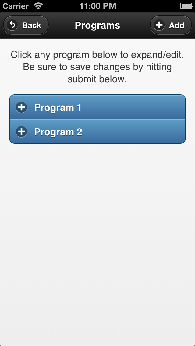
Now let me go back to talk about the OpenSprinkler mobile web app that Samer wrote. Here are a few screenshots from his blog:

os_webapp1os_webapp3os_webapp2os_webapp4

os_webapp5os_webapp8os_webapp9os_webapp10

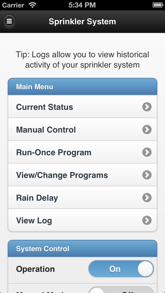
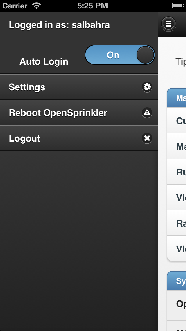
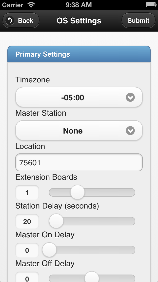
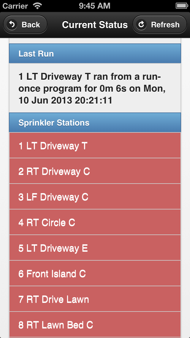
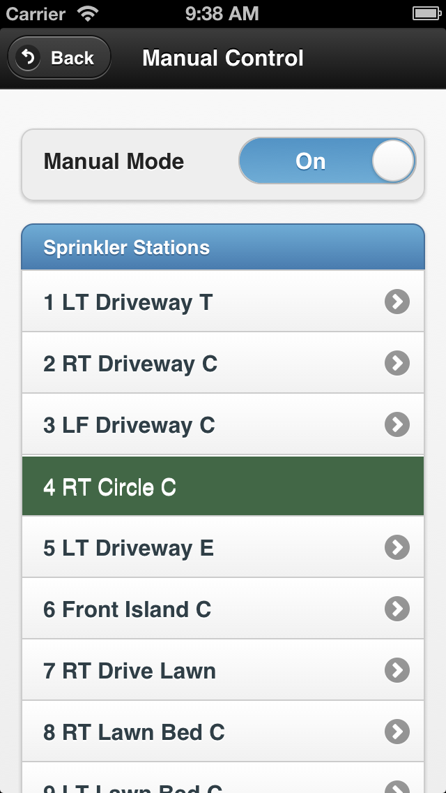
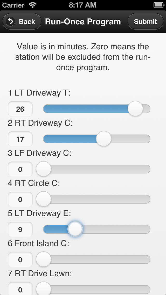
Very sleek and clean. Gotta love it! The app currently supports the complete set of features in OpenSprinkler firmware 1.8.3 (and equivalently 2.0.0 for OpenSprinkler v2.0s users). You do probably need to refer to the OpenSprinkler Online User Manual for detailed explanations of specific settings, but the app itself is quite intuitive to use and self-explanatory.

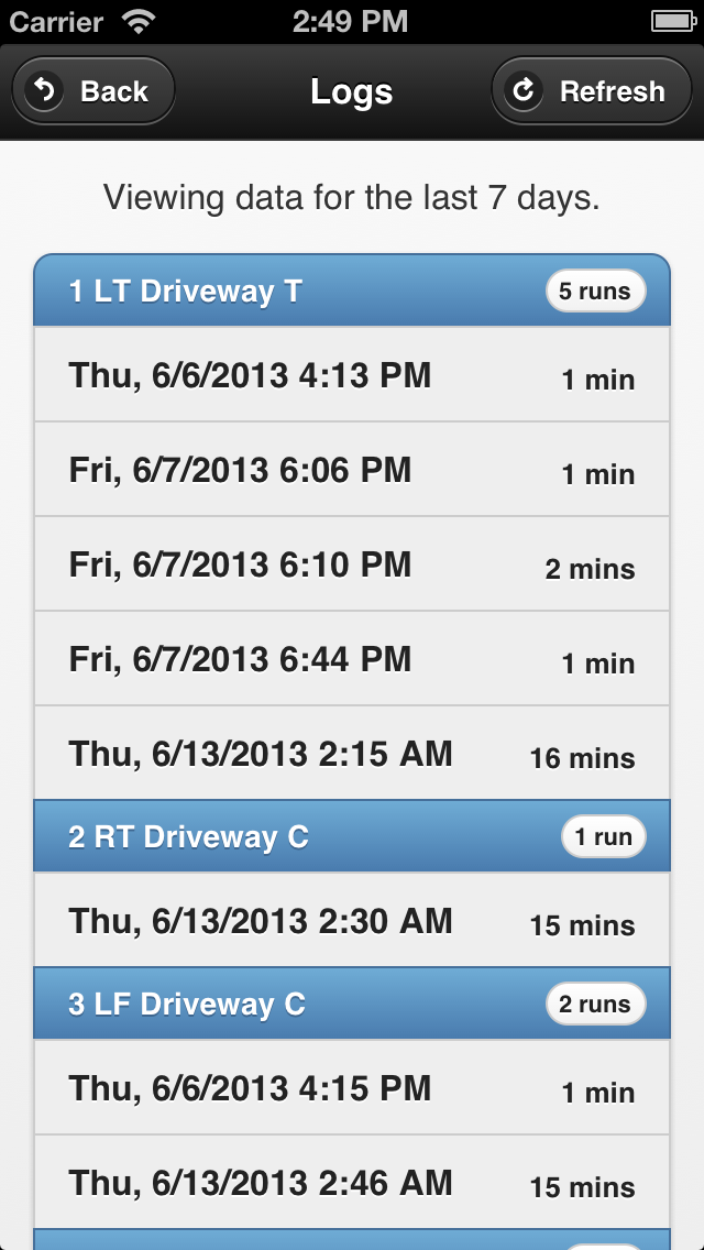
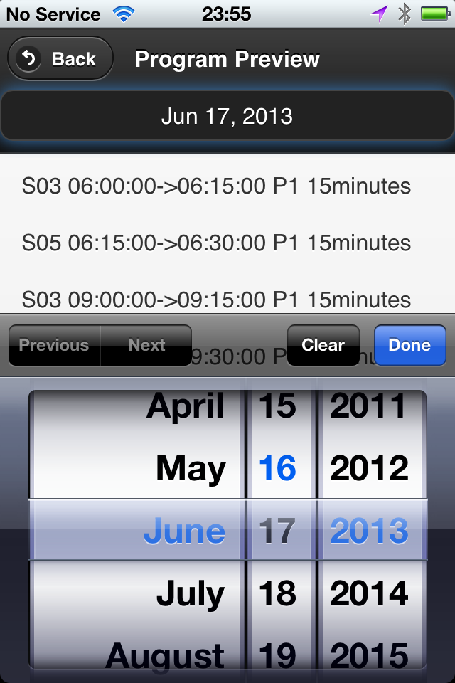
Not only does it support the complete set of firmware features, it offers additional ones, notably:

  • A logging feature (i.e. records of watering events).
  • The ability to select an arbitrary day in program preview.
  • The app is self-contained (implemented using PHP) and does not rely on external Javascripts, so you can use it to access OpenSprinkler locally without Internet connection.

These really help improve the user interface significantly. Also, as mentioned before, the app is cross-platform: the same app runs on iOS, Android, as well as Desktop browsers.

os_webapp12os_webapp13IMG_1239

How to Set it Up (using Raspberry Pi as example)

To set up the web app, you need to have an HTTP server with PHP support. There are many options, for example, a desktop server running Ubuntu Linux, a Raspberry Pi, or an external server. In the following I will use Raspberry Pi (RPi) as an example since it can be used as a low-cost web server. The steps should be the same for desktop servers. For details, please refer to Samer’s GitHub repository (link given above). In addition, you will need an OpenSprinkler running firmware 1.8.3 or above, or OpenSprinkler Pi running the interval_program ported by Dan.

Step 1. Install the necessary packages

  • sudo apt-get update
  • sudo apt-get install apache2 php5 libapache2-mod-php5 git

Step 2. Create direcotry

  • sudo mkdir -m 777 /var/www/sprinklers

Step 3. Clone Samer’s GitHub repository

  • sudo git clone https://github.com/salbahra/OpenSprinkler-Controller.git /var/www/sprinklers/

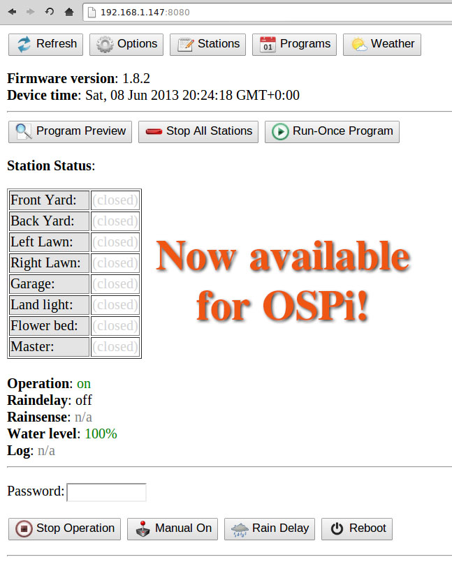
This will download and copy necessary files to the /var/www/sprinklers/ directory. Once these steps are completed, you can open a web browser (either desktop browser or mobile browser), and type in the IP address of your RPi, followed by /sprinklers. For example, my RPi’s IP address is 192.168.1.147, so I type in:

  • http://192.168.1.147/sprinklers/

You should then see a setup page that requires you to type in some necessary information. In particular,

  • An account including user name and password.
  • Your OpenSprinkler’s IP address (including port number if it’s not the default 80).
  • Your OpenSprinkler’s access password (‘opendoor’ by default).
  • Un-check the ‘Force SSL’ checkbox, unless if you are sure you server has the proper SSL setup.

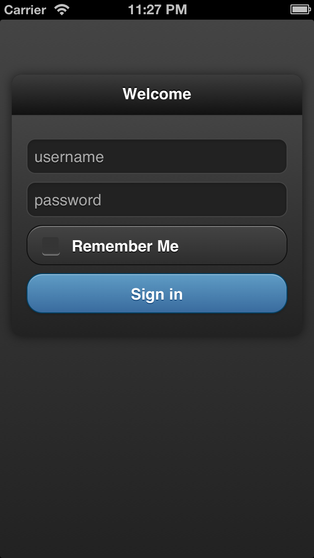
Once your settings are saved, you will be automatically directed to a login page (or if not, you can directly type in the web url again: http://192.168.1.147/sprinklers/). Type in the account you created above, and then you should be directed to the app’s homepage. I recommend you to bookmark this page to your home screen (most mobile browsers support this), so that next time you can simply click on the home screen icon to access the web app. From this point on, you can feel free to play with the app, and check all the features it supports. I will probably make a video demo at some point to give you a visual walk-through of the app.

In case your settings are changed, you can open /var/www/sprinklers/config.php to change the information there accordingly. Since this is a un-encrypted text file, you probably want to restrict its access right for security reasons (e.g. sudo chmod o-r /var/www/sprinklers/config.php)

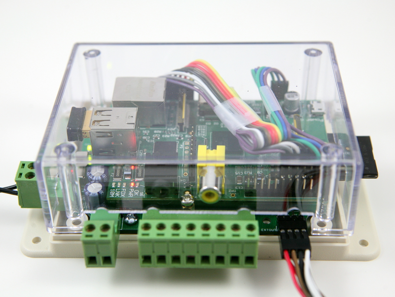
For OpenSprinkler Pi Users

If you are an OpenSprinkler Pi user, you don’t need to install any additional RPi or HTTP server: the same RPi that drives your OSPi can be used to serve the web app! Just follow the instructions above to install apache2, php5 and the other goodies. Your Python-based interval_program can run in conjunction with the HTTP server in the background.

At some point it will make sense to combine the Python-based program and PHP-based web app into a single program that serves both the front-end (UI) and back-end (scheduling algorithms). This would be awesome for the OpenSprinkler Pi in the future.

Acknowledgement

Finally, a big thank-you again to Samer Albahra, who wrote this app and made it available to the public. This is yet another evidence of the spirit of open-source development.

Keep in mind that the web app is continuously being improved and supported, and we can use your feedback and suggestions for making it better and fixing bugs. Please leave your comments and suggestions at the Rayshobby Forum. Thanks!


OpenSprinkler Interval Program is now available for OSPi

Good news to the OpenSprinkler Pi users: the same interval program firmware that runs on the latest OpenSprinkler has now been ported to OpenSprinkler Pi! This is due entirely to the generous contributions by Dan Kimberling, who ported the OpenSprinkler’s Arduino code to Python. The code is available for download at Dan’s GitHub repository. Instructions can be found at the Rayshobby Wiki page:

(Note: the grayed-out instructions below are obsolete and are only kept here for archiving purpose. Please follow the instructions on the Wiki page above for how to install and use the latest software. Thanks.)


For anyone who is unfamiliar with RPi, here are some basic instructions to follow:

  • First, ssh to your RPi (or connect your RPi to a monitor and open a Terminal), and type in run the following command in one single line(i.e. the ‘wget’ command, space, and the very long link): wget https://github.com/rayshobby/opensprinkler/raw/master/OpenSprinkler%20Pi/software/demos/interval_program/ospi.tar.gz
  • Next, run tar zvxf ospi.tar.gz. This will unzip the file to a subfolder named OSPi in your current directory.
  • Now, cd OSPi, and then run sudo python ospi.py (note that you will need to type in your RPi account password). This will start the web server.
  • Open a browser on your computer or any device that’s connected to the same network as your RPi, and type in your RPi’s IP address, followed by colon, and the default port number 8080. For example, for my RPi, the address is http://192.168.1.147:8080. You should now see the homepage of the interval program demo. Note that the port number can be changed to other values, in which case you need to check the source files to figure out how to make the change (or post a message on the forum and I am sure someone will help you).


interval_program_ospiospi_header

This demo program is the same as OpenSprinkler 1.8.2 firmware. So you can follow the OpenSprinkler Online User Manual for usage instructions. I believe all features of the firmware are supported. Keep in mind that this is still work in progress, so there are glitches and bugs that will be ironed out over time. If you are a developer, you are welcome to improve the code or help fixing bugs. The backbone of the software is based on web.py, a popular and easy-to-use web framework for Python.

Also keep in mind that if you have RPi rev. 2 (which is the current model), you need to open ospi.py and edit a port number. Details can be found in the README.txt file. P.S., it’s generally a good idea to read the README.txt first before you start doing anything.

These will be the basics to get you started. If you have any questions, feel free to post a message on the forum.

Finally, a big thank-you again to Dan Kimberling for his time and efforts in making this available to the public. This is an example of the true spirit of open-source development and community support. I am very excited to see additional user contributions to the OpenSprinkler Pi project!

Annoying ribbon cable problem with recent orders of OpenSprinkler Pi

Hi, this is an alert to users who recently ordered OpenSprinkler Pi: we’ve found an annoying problem with the 8-pin ribbon / rainbow cable that comes with the package. Apparently many of the cables have disconnected crimp wires, causing the OSPi to not respond to RPi, or even worse, causing all stations to turn on at the same time. I estimated that there are potentially up to 60 orders that might be affected. We’ve proactively taken actions to send a replacement cable to everyone who ordered OSPi recently (within the last 2 weeks). If you are seeing an issue of your OSPi not responding to RPi, try to use a multimeter to measure the connection on each of the 8 wires of the cable. If any wire is not connected, please email to [email protected] and we will send you a replacement cable right away.

Here is a closer look at the cause of the problem. When I take the wire out of the crimp connector, you can clearly see that the good ones (shown on the left below) have metal wires tightly secured by the crimps, while the bad ones (shown on the right below) have the metal wires cut from the cable, resulting in disconnection. This is probably due to a defective wire stripper or crimp tool, or incorrect operation that causes the metal wires to be completely cut through. In any case, I’ve informed the supplier and complained about the the quality, and will never order from them again.

IMG_2963IMG_2965

So the lesson to learn here is that when testing OSPi, we really should use the individual cable that goes with each board, instead of using a common testing cable. Another lesson to learn is to never overlook any part, even something as simple as a cable!

I became aware of the cable issue when a couple of users reported that their OSPi did not work. This is very puzzling because every single board has been tested and verified, so the chance of DOA is very small. I’ve asked two of them to send their boards back to me, and after testing, I couldn’t find any obvious problem — the board works fine, and all demo programs work fine. However, until yesterday, I have apparently overlooked the problem with the cable: when testing, we have always used a common testing cable, instead of the user’s cable. Partly it’s because I never thought the cable would have any problem at all. Now I’ve learned a lesson, and it’s a good lesson to learn!

New Development PCB in the Mail Today

Yup, I opened my mail box and found the lovely purple envelope from OSHPark. What’s in it?
IMG_2720IMG_2721

Ah ha, it’s the new AASaver 2.0 prototype PCB. I can’t help getting my hands on it, so I quickly assembled two. Here is what the assembled board looks like (without and with AA batteries):

IMG_2722IMG_2723

AASaver 2.0 is sort of a ‘mega’ version of AASaver 1.0: like 1.0, it takes two AA batteries and serves dual functions as both an LED flashlight and breadboard power supply. But it can do much more. First of all, I’ve added a LiPo charger circuitry so that you can use two AA batteries to charge an external LiPo battery:
IMG_2728IMG_2726

I’ve also added an SMT potentiometer (trimmer) to adjust the charge current (see the picture on the right above), anywhere from 20mA to 100mA. This is not a random addition — there is a good reason to have this feature, which you shall see in a minute.

Another BIG addition is the functionality to charge USB devices like cell phones. Yup, you heard it right: there is a built-in type A USB receptacle that allows you to plug in a USB charging cable to add juice to your phone, MP3 player etc.

IMG_2725

So this is similar to Adafruit’s MintyBoost, except that there is a catch: on MintyBoost, you use a pair of fresh battery to charge the phone, but with AASaver the whole point is to harvest the remaining energy in used or old batteries. How does this affect anything? Well, used batteries typically cannot supply a high amount of current, so you can’t use them directly to charge the phone — it simply won’t provide enough current to charge. The trick is to dump the energy slowly into a LiPo battery, then charge the phone through the LiPo battery later! Essentially the LiPo battery serves as a ‘water bucket’, which accumulates charges slowly (like water drops), so that even used AA batteries can charge it; once the ‘water bucket’ has accumulated enough charges, it can dump the ‘water’ at much faster rate. This is the same idea as how solar chargers work: solar cells are too weak to charge phones directly, but you can build up the charges by leveraging a battery. Now you see why there is a built-in LiPo charger!

The picture below shows where the LiPo battery should be plugged in when you want to use it to charge USB devices. In sum, if you have a fresh pair of AA batteries, you can charge USB devices directly; otherwise you first charge the LiPo battery with a controllable charging current (20mA recommended), then use the LiPo to charge USB devices. The circuit of AASaver 2.0 accepts either AA or LiPo as the source of its boost converter, and directs the boosted 5V to either USB port, or LiPo charger, selectable through the ‘Target’ switch at the right-end of the board. On top of these, there is a separate switch for turning on the flashlight LEDs, and there are pin headers spaced appropriately to match a standard breadboard, so you can use it as a battery-based breadboard 5V power supply. As you can see, it has a load of new features to provide better and more flexible ways to save your AA batteries 🙂

IMG_2727IMG_2728

IMG_2727IMG_2724

OpenSprinkler Orders Delayed

There has been an unexpected delay in the enclosure processing: the order was supposed to arrive by Monday this week but is now pushed back to Friday next week. As a result, all orders that include an OpenSprinkler enclosure will be delayed. I am really sorry about the delay. It is unfortunate and unexpected. The way we currently order enclosures is through Electronic Precepts (http://electronicprecepts.com/): they order in bulk from Serpac and machine custom cutouts for us. While on vacation last week, I sent an inquiry email and learned that there will be a delay due to machine down time. Initially I was told it would come today, but the latest status is that it’s more likely to come Friday next week. I know the folks who have ordered OpenSprinkler / OpenSprinkler Pi have been waiting eagerly for their orders to arrive. Sorry about that! I wish I had control over the enclosure processing. Meanwhile if you want to cancel the order, or want to receive the board first and enclosure later in a separate package, feel free to let me know. Thanks for understanding!

OpenSprinkler Hardware v1.4 Released

About two weeks ago we started shipping out OpenSprinkler v1.4, and I figured it is now time to write a short post to announce it. What are the new updates in v1.4?

• DS1307 RTC
The main update is that the external EEPROM (24LC128) is replaced by a DS1307 Real-Time Clock (RTC). I am aware that RTC has been requested since the beginning of OpenSprinkler, and I apologize for taking so long to add it. There are multiple reasons: the limited PCB space, the cost of DS1307, and the fact that NTP sync is often good enough. The limited PCB space is probably the biggest reason. Fortunately since the latest interval program does not use external EEPROM any more (i.e. everything is stored in internal EEPROM), there is now space to add RTC. The software has also been updated to support DS1307. Specifically, if RTC is enabled in options, the controller will not rely on NTP to get time any more. In addition, there is an on-board button cell battery which will keep the time running even when power is lost.

If you own a previous version of OpenSprinkler which does not have built-in DS1307, you can easily add an external RTC module, available in Rayshobby shop. Our module comes with a built-in rechargeable battery, pin headers, and jumper wires for easy connection to your OpenSprinkler board. Follow this link for instructions on how to connect. These modules are also available on eBay, or Adafruit, or SparkFun, but they are usually pricier and without jumper wires.

• Screw Terminals
As you may have noticed from the pictures, the screw terminals have been upgraded to the two-piece (plug and socket) type, which makes it easier for installing and uninstalling wires. Now when you need to make changes to wires, you can simply take out the plug piece, insert and tighten wires, and plug it back in. There is no need to open the enclosure.

• Pin Changes
The second update is that a few pin assignments been changed to free up analog pins A2 and A3. These pins are precious for connecting to external sensors. Also, digital pin D3 is now wired internally to the rain sensor, so you no longer need to solder a separate wire. As in previous version, if you are not use the RFM12B transceiver, digital pins D2 and D10 are also free to use.


• Surface Mount Version
The last major change is that there is now a surface mount (SMT) variant 1.4s, which uses the same circuit as the through-hole version 1.4u but most components have been changed to surface mount package. This variant is created to improve our productivity of full assembled and tested kits. So from now on, all orders of fully assembled kits will receive the SMT version, while the DIY kits will continue to use the through-hole version.

The images below are close-up views of the SMT version (front and back):

As you can see from the front image, most components are surface mount, except the peripheral components like screw terminals, connectors, buttons, and big capacitors. Two crystals and the button cell battery for RTC are on the back side. The SMT version uses the same software as the through-hole version, but it does have a few differences:

  • It has two extra analog pnis A6 and A7, which are accessible in Arduino programs.
  • The Ethernet connector is changed from SparkFun RJ45 jack to Hanrun 911105A, which is less expensive and more widely available.
  • There is a slide switch on the top-left corner of the PCB. This is used internally by us to switch between programming ATtiny45 and ATmega328. You should keep it in the ‘INT’ position.

Future Plans

To give you a heads-up, version 1.4 is likely to be the last one in this hardware generation, and will also be the last through-hole version. The next version OpenSprinkler 2.0 will be SMT only, and will switch to a completely different microcontroller in order to accommodate new features like better user interface, on-board wifi, logging, and more sensor options. However, the development of 2.0 will likely take more than a year, so it won’t be available until after summer next year (2013). Meanwhile, feel free to send me comments and suggestions on how to improve the OpenSprinkler functionality, and I will consider them for version 2.0!


Update and New Products in Rayshobby Shop

The past month has been a bit crazy. I just completed a series of traveling from mid-July to early August. It’s really hard to get work done while traveling. The good news is that I am back now, refreshed and energized to crank out some new projects.

AASaver v1.1 back in stock

The first bit of news is that AASaver v1.1 is now back in stock and available in my hobby shop. If you’ve noticed from my earlier post, version 1.1 improves upon the original version by adding a switch to control the LEDs, so the same board can be used simultaneously as breadboard power supply and LED flashlight. Another update is that both LEDs are moved to the same side so they point to the same direction. The separate LED switch was actually a suggestion made by Michael Castor from MakerShed. So I would like to thank Michael for making this suggestion. The original plan was to sell AASaver in MakerShed. However, due to some of their policy changes, that plan fell through. Nonetheless, AASaver has been quite successful and more than 370 have been sold to date. It got posted on Hack a Day, Adafruit blog, and also got reviewed by Dave Jones on his EEVblog. Anyways, if you have any suggestions for the AASaver, please let me know and I will consider them for the next update.


434MHz RF transmitter/receiver pair

A couple of new products have also become available in my hobby shop. The first is a 434MHz RF transmitter/receiver pair. These are compatible with similar products you can find at SparkFun or other retailers. It’s inexpensive, and is very handy for implementing wireless communication for your microcontroller projects. In addition, I have been using the receiver to reverse engineer wireless power sockets, remotes, and sensors, and using the transmitter to simulate or interface with these devices. Check my blog post here for an example of how to use them. If you are only interested in the RF transmitter, you can get it separately from my shop page.


DS1307 RTC module with built-in battery

This is a DS1307 Real-Time Clock (RTC) module that has built-in 3V rechargeable lithium battery and recharging circuit. Very handy for projects that need offline time keeping. To use this module, connect four pins: Vcc, Gnd, SDA and SCL. Note that Vcc must be connected to +5V: it won’t work with +3.3V. You can find DS1307 Arduino library from the Arduino Playground, and a variety of other websites. The module also comes with an on-board 4KB EEPROM that uses the same I2C interface, a 1×4 pin header, and female-female jumpers for easy connection to your existing projects, such as OpenSprinkler kits that do not have built-in DS1307. Highly recommended!


DHT11 Temperature/Humidity Sensor

This DHT11 Sensor is the first product in the Sensors category. It is a low-cost temperature and humidity sensor that requires only one digital I/O pin to read both temperature and humidity values. Very handy as an add-on sensor to OpenSprinkler. The operating voltage is 3-5V, and measurement range is 20%-80% humidity (5% accuracy), 0°-50°C temperature (±2°C accuracy). You can find the product datasheet, an Arduino tutorial by Adafruit, and an Arduino library from the product link above. Note that Adafruit’s library does not work with 8MHz Arduino, which is what OpenSprinkler is running at. So i recommend the library at the third link on the products page.


USB-to-Serial (TTL) Converter

This product has been mentioned in an earlier post, but I just want to bring it up again since it has been very popular. It is an integrated USB-to-Serial converter based on Prolific PL2303HX chip. ‘Integrated’ means the circuit is in the USB connector itself, so it’s quite compact. This inexpensive converter is very handy for debugging and creating serial communication. To use it you usually only need to connect three pins: Gnd (black wire), TX (green wire), and RX (white wire). Keep in mind that TX should be connected to the RXD pin of your microcontroller and vice versa for RX. No driver is necessary under Linux. For Windows and Mac, follow the product link to download driver. Once installed, The device will report as a Serial COM port. You can then use Arduino’s serial monitor, putty, gtkterm, or any of your favorite serial monitor to talk to it.


So much for the product update. There will be a few follow-up posts about the update of OpenSprinkler and SquareWear. These are more major updates that I have to talk about in separate posts 🙂

OpenSprinkler Hardware v1.3u Released

Ok, this post is a bit late, as 1.3u has already started selling since Tuesday this week. Anyways, 1.3u is a minor revision since 1.2u. There are only a few changes (see Release Notes for details), so I didn’t make a release video. This post explains why these changes were made and some of the technical details.

  1. Added shift register OE (output enable) line
  2. This is mainly to address an issue with 74HC595 shift register that on powering up the output values are undefined. This can potentially lead to valves being randomly turned on for a short period of time before the mcu takes over and clears output values. It is not a huge issue, but quite annoying. It turns out that one simple solution is to add a control line to the 74HC595 OE (output enable) pin. This pin is active low, which means when set to low it enables output, and when set to high, it forces the output to be in high-impedance state, therefore the triacs will not turn on and the valves will remain closed.

    In 1.3u, Arduino digital pin 3 is assigned to control OE, and a pullup resistor is used to pull the pin high by default. On start-up, before the mcu takes over, OE is high, disabling output; then when the mcu completes initialization, it sets OE to low, enabling output. That’s it. Simple solution.

    Because of the added line, the extension board connector has been changed to 2×4 format (previously it was 2×3). If you own a previous version of OpenSprinkler and would like to use 1.3u extension board, you just need to solder a wire between the OE pin and Gnd , in order to enable output by default.

  3. TXD/RXD are now used as general I/O pins.

    This change was made to free up the A2 and A3 analog pins, since there have been many requests to make more analog pins available in order to connect external sensors like temperature and humidity sensors. Because TXD and RXD are now used as general I/O pins, they can no longer be used for Serial communication. In fact, since they are not used to control the LCD, calling Serial.begin() or Serial.print will cause the LCD to display garbage. If you need Serial communication, you can use the SoftSerial library which can simulate Serial communication on any pins.

  4. Added coin battery holder.

    Warning: this is a feature under development. It requires software support which is not available yet. The goal is to have a backup battery which allows the mcu to continue time keeping even when power is lost. Actually the easiest solution would be to just add a DS1307 Real-Time Clock (RTC). But my main hesitation is that DS1307 is quite pricy. Well, it’s not hugely expensive, but at $2 a piece (volume pricing), it is actually more expensive than the ATmega328 mcu. Isn’t that a bit silly? Anyways, the time keeping business can be well handled by the mcu itself. First, the mcu can run at a voltage as low as 1.8V, so when power is lost, it can continue running on a low-voltage battery; second, during power loss, the mcu will mostly be in sleep mode, using an external 32.768 kHz clock source, and occasionally waking up to update the time counter. This way, it can basically do whatever the RTC chip can do.

    The only tricky part is detecting power loss (which is already possible with the Power Sense pinout), and turning off peripheral components such as the Ethernet controller to minimize power consumption during sleep mode. These require some further experiments, which have been put on my todo list.

Another minor change is adding two resistors for the LEDs on the RJ45 Ethernet connector. In OpenSprinkler v1.1 and v1.0, the Ethernet connector did not have built-in LEDs. Then when I changed to use SparkFun’s RJ45 in v1.2, I forgot that it actually has built-in LEDs… So in this version the LEDs are wired in, which makes the circuit more complete 🙂

That’s all for OpenSprinkler v1.3u update. In case you are wondering about the frequent hardware changes, keep in mind that we are continually improving the design based on feedback and comments received from users. We run small batches (a couple hundred) for each version, that’s why we can have quick turn-around time in integrating new hardware features. At some point when the hardware becomes mature, we will make a surface mount version to improve the production throughput. Hopefully that point won’t be too far away!

New Products in Rayshobby Shop

A couple of new products have been just added to Rayshobby Shop page. These include a 434MHz RF transmitter and a USB-to-Serial (RS232) converter.

So what are they good for? The 434MHz RF transmitter is a general-purpose RF transmitter with on-board PCB antenna. It is compatible with SparkFun’s 434MHz RF transmitter. You can find a lot of example code online, including Arduino code. The module has three pins: Vcc, Gnd, Data. The operating voltage is 3~12V (5V standard), and the current draw is about 5-15mA. The higher the voltage, the longer the transmission range. Typical transmission range without external antenna (i.e. using on-board antenna) is 160 feet; and it extends to 500 feet with an external antenna. I’ve shown an example use of the transmitter in a recent article A New Way to Interface with Remote Power Switches. It provides a simple way for a microcontroller to switch wireless power sockets. Very handy and inexpensive for home automation projects.

The USB-to-Serial converter is an integrated cable based on Prolific PL2303HX chip. It is a convenient tool for microcontroller to host communication through USART. It is similar to an FTDI cable, but at a significantly lower price. It doesn’t have a Reset line though, so it cannot be used for re-programming Arduino or OpenSprinkler v1.1/v1.0. However, it is very handy to connect to your OpenSprinkler v1.2’s TXD/RXD pins in order to easily debug your code. The cable length is 3 feet (1 meter). The wires are colored as follows:

Red->+5V supply, Black->Ground, Green->TXD, White->RXD

On Mac or Linux, you don’t need to install any driver: it is already supported by the operating system. On Windows, you can download the driver following the link here. Once installed, the device will report as a Serial COM port. You can then use any Serial Monitor to communicate with your microcontroller. Some standard serial monitors are Arduino’s built-in serial monitor, Putty, or gtkterm (on Linux). I’ve been using this converter a lot for printf debugging of OpenSprinkler code.

Again, both of them are now available for purchase on Rayshobby Shop page.

AASaver Kit v1.1 is in stock

AASaver kit is now back in stock. There was a bit of delay in the shipping, but it has finally arrived! The funny thing is that the updated version (v1.1) arrived ahead of the original version, so if you place an order now, you will received the updated version, with additional features, at the same price!

Picture of v1.1

Here is the list of changes in v1.1:

  • Moved both flash LEDs to the same side so they point to the same direction.
  • Added an on-board resistor (R1) for the flash LEDs.
  • Added a separate flash LED switch.
  • Moved the power switch to the bottom side.

These changes were made to improve the usability. For example, the separate LED switch allows you to use it simultaneously as a breadboard power supply and flashlight (previously it was either one or the other). Also, the two LEDs now point to the same direction, so it can function better as flashlights.

The kit is available in my hobby shop. As I said, if you place an order now, you will get the updated v1.1 at the same price, until it runs out.