OpenSprinkler Pi v1.02 Released

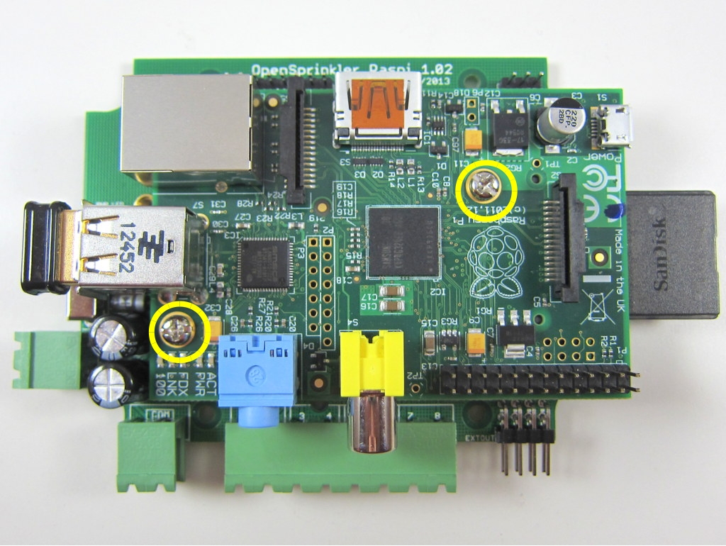
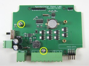
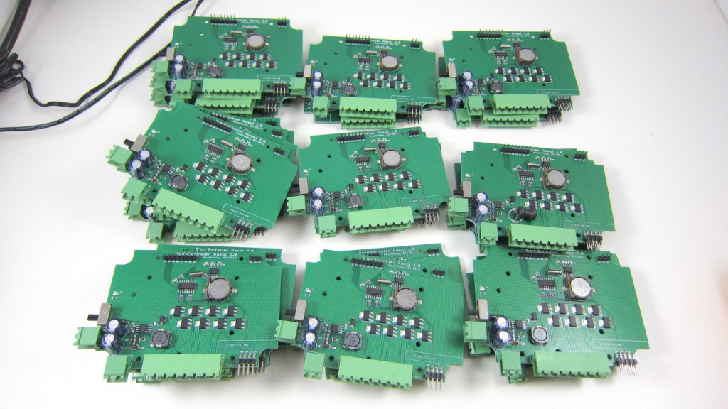
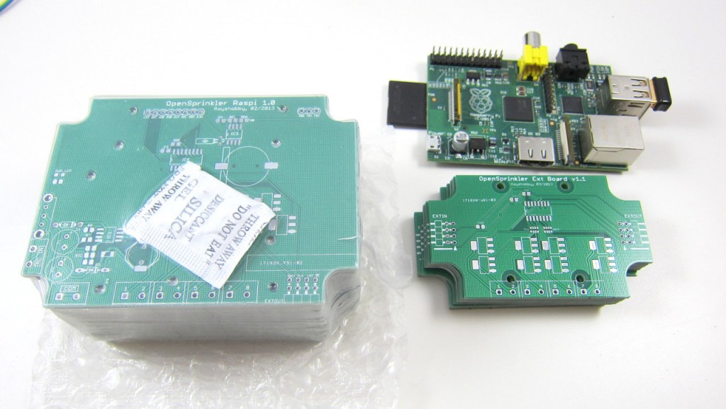
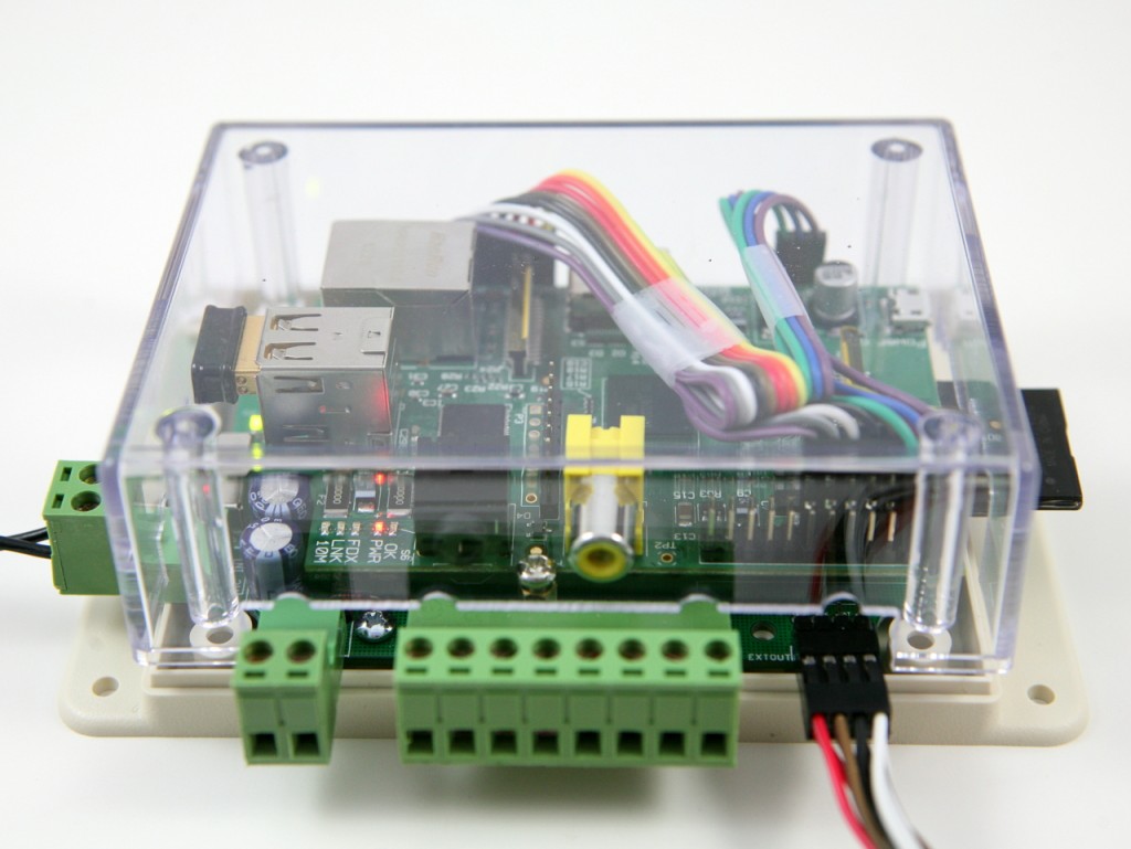
I’ve made a minor update to OpenSprinkler Pi (OSPi), and the new version v1.02 has improved design of the separation pillars in order to make use of the screw holes available on Raspberry Pi rev. 2. See the picture below:
IMG_2669_a
This way, the Raspberry Pi rev. 2 can be more securely attached to the OSPi even with just two screws.

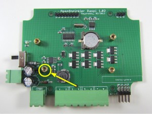
If you own a Raspberry Pi rev. 1 instead, don’t worry, you can still attach it to OSPi using the two edge screws (see the picture on the right below), in the same way as the original OSPi. To do so, you will need to move one of the separation pillars. See the picture on the left below (sorry, the arrow is pointing in the reverse direction).

IMG_2670_aIMG_2666_a

So in sum, the updated version OSPi v1.02 allows you to make better use of the screws holes available on RPi rev. 2 while still being compatible with RPi rev. 1.

OpenSprinkler Orders Delayed

There has been an unexpected delay in the enclosure processing: the order was supposed to arrive by Monday this week but is now pushed back to Friday next week. As a result, all orders that include an OpenSprinkler enclosure will be delayed. I am really sorry about the delay. It is unfortunate and unexpected. The way we currently order enclosures is through Electronic Precepts (http://electronicprecepts.com/): they order in bulk from Serpac and machine custom cutouts for us. While on vacation last week, I sent an inquiry email and learned that there will be a delay due to machine down time. Initially I was told it would come today, but the latest status is that it’s more likely to come Friday next week. I know the folks who have ordered OpenSprinkler / OpenSprinkler Pi have been waiting eagerly for their orders to arrive. Sorry about that! I wish I had control over the enclosure processing. Meanwhile if you want to cancel the order, or want to receive the board first and enclosure later in a separate package, feel free to let me know. Thanks for understanding!

OpenSprinkler March 2013 Update

Tomorrow we will be flying south to Peru for a one-week spring vacation (yes, that’s right!) I am very excited about the trip, and am looking forward to visiting Machu Picchu 🙂 Before I go off and get lost in exploring the ancient world, some quick updates about what’s happening recently:

  • OpenSprinkler Pi is back in stock as of last week, and about 50 have already been shipped out. One user on the Rayshobby forum, Ric, pointed out that the original Python demo code only worked for RPi rev. 1. It turns out, as Ric discovered, that RPi rev. 2 has changes the pin numbers of a few GPIO. So if you own a rev. 2, you should update your code from GitHub, and follow the instructions in README.txt to modify a pin number in your Python code. Thanks Ric for finding this out!.
  • OpenSprinkler 1.4u will be the last DIY, all through-hole version. As soon as it sells out (there are only a couple of them left in stock), we will discontinue the DIY kits. The main reason is that the support overhead for DIY kits has gradually become too high for me. Although we don’t officially provide any assembly support for DIY kits, when users get into trouble and can’t fix problems themselves, I hate to see them go and have to jump in to help, sometimes even asking them to send the kits back to me so I can fix soldering mistakes for them. This is simply not sustainable any more. One way to solve the issue is to have a community of people to help each other, but i don’t see that happening on OpenSprinkler any time soon. So the only solution is to let go the DIY version. Sorry folks!
  • We will be going to the Bay Area Maker Faire again this year. I’ve just submitted the proposal to Maker Faire and hopefully it will be accepted. If you are planning to be there too, feel free to come by, hang out with us and watch demos 🙂
  • Since we are going off for vacation, we won’t be shipping packages until Monday March 25. Meanwhile I will still be checking emails, although probably no more than once a day.

All right, time to pack and prepare for the trip tomorrow. Thanks for reading this post!

Machu_Picchu

Custom OpenSprinkler Enclosure — Part II

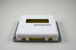
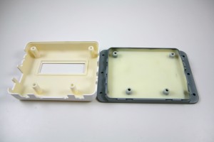
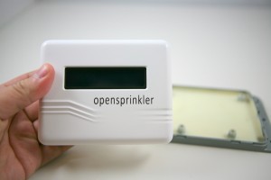
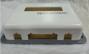
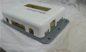
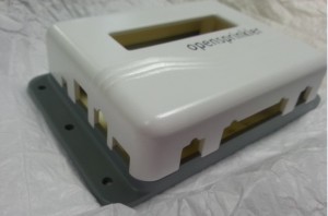
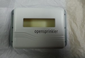
Today I received the 3D printed prototype enclosure from Seeed. It was supposed to arrive on last Friday but due to a snow (which affected nothing) DHL didn’t deliver that day. In any case, I got it today, and it is beautiful! Check out the pictures below:

IMG_2424IMG_2425

IMG_2426

A couple of quick notes:

  • The new enclosure will use opaque material (instead of transparent plastic as the current enclosure). So there is now a cutout for the LCD on the top. This will give it a more professional look.
  • The designer at Seeed recommended a clever design that uses a single set of 4 screws to simultaneously fix the top and bottom pieces together, and the PCB in the middle. This reduces the number of screws and provides more PCB space.
  • There is now a cutout for the expansion board connector which makes it easy to plug in cables without opening the enclosure.

Overall I am very satisfied with the prototype. There is still some verification I have to do to make sure the PCB and components fit well with the enclosure. Hopefully I will place the mold order soon!

Custom OpenSprinkler Enclosure using Injection Modeling

As mentioned in a previous post, I have been working with SeeedStudios to design a custom OpenSprinkler enclosure. Thus far I have been using an off-the-shelf Serpac WM-032C clear plastic enclosure, and I have Electronic Precepts to machine the cutouts. It was a good start and really easy to design, but the cost can quickly add up as I order more from them. Over time, it’s make more and more sense to design a custom enclosure using injection molding, in order to reduce the per unit cost.

The initial design has been finalized and a 3D printed prototype is on its way to me. I am very excited because this will be the first injection-molded OpenSprinkler enclosure! It’s a pretty heavy one-time cost (the mold costs about $5,000 to make), but it’s fun and I think it’s worth the investment. I am supposed to receive the prototype today, but a snow prevented DHL from delivering today. So I have to look forward to Monday. But below I attached some pictures Seeed sent me. They are enough to enjoy for a while 🙂 More pictures will come after I receive it on Monday.

opensprinkler 1opensprinkler 2

opensprinkler 3opensprinkler 4

OpenSprinkler Pi Back in Stock

OpenSprinkler Pi (OSPi) v1.0 is back in stock and available for shipping now. The kit includes one assembled and tested OSPi board, separation pillars, terminal blocks, 8-pin and 3-pin connection cables, and optional enclosure. You need to provide your own Raspberry Pi, and 24VAC sprinkler transformer. The board controls 8 zones, and can connect to standard OpenSprinkler zone expansion board to enable additional zones. Grab it now before it goes out of stock again!

IMG_2416

I would really like to give a big thumb-up to smart-prototyping.com. This is the first time I ordered PCBs from them (I got the link from dangerousprototypes.com), and I wasn’t sure what to expect. The order was placed on Feb 26 right after the initial batch of OSPi sold out. I selected DHL shipping (about $30) since I need it to be quick. On Feb 28 I decided to place a smaller order for the new zone expansion board prototype PCB, and I selected economy air shipping (about $4) since I don’t care how fast it comes. Then on March 5, exactly one week after placing first order, I noticed it got shipped out. I happily received the package on March 7. This is a total turn around time (from ordering to delivery) of only 9 days! What’s more surprising is that when I opened the package, I found my second order is also included. They must have figured out that since both orders are going to the same address, and both were ready upon shipping of the first order, why not put them together and use the fastest shipping. Clever! I am really impressed by their processing speed and the super-fast shipping time. Also, the PCB quality is very good, and their price is even cheaper than SeeedStudios. Highly recommended, and will definitely order from them again!

IMG_2415

OpenSprinkler Pi (OSPi) 1.0 — a sprinkler / irrigation extension board for Raspberry Pi


Hi, I am glad to announce the arrival of OpenSprinkler Pi (OSPi) 1.0 — a sprinkler or irrigation extension board for Raspberry Pi that provides direct access and control of sprinkler valves. This post serves as a quick introduction to the hardware and software setups. A more dedicated webpage will be available soon. First off, a picture of the board:

ospi_header

and a video introduction:


Background

Since the beginning of Raspi, there have been many published DIY projects on how to use Raspi for home automation need. I bought a Raspi a few months ago, and have been quite happy with it since then, but I at that point I had not thought about designing an OpenSprinkler extension board for it. The idea of OSPi first came when I noticed that several OpenSprinkler users were setting up Raspi to work with OpenSprinkler. There are many good reasons to do so, for example, to enable logging, to customize the default Javascript files, and to allow more advanced features such as weather-based and learning-based control. At one point I started thinking: wouldn’t it be nice to design an extension board for Raspi, so that it can directly talk to sprinkler valves through the GPIO pins, without an additional layer of microcontorller and Ethernet controller? This has been on my todo list for quite a while, until one day I was playing with Raspi, and I suddenly that the I can actually fit a Raspi inside the existing OpenSprinkler enclosure. As soon as I figured this out, I couldn’t resist ordering a small batch of prototype PCBs right away.


The content below has been updated and moved to a dedicated product page for OSPi at http://pi.opensprinkler.com.


OpenSprinkler Firmware 1.8.3 Released

Amid all the fun and exercise of snow shoveling following the heavy snowstorm Nemo, I was able to finish and check in a new firmware update for OpenSprinkler. This new firmware, numbered 1.8.3, is a relatively minor update. You don’t have to update if you don’t need the new features explained below. There are two main changes:

The first is adding back the Sequential option that was available in firmware 1.7 but disabled in 1.8 due to a bug that was tricky to fix. This option allows you to set the controller to run in either sequential mode (where station runs are serialized) or concurrent mode (where stations are allowed to run simultaneously). The support for this option is now added back (with the bug fixed), and the Program Preview Javascripts have also been updated so you can easily check and verify the controller schedules in concurrent running mode. For most people this is probably not that useful, because sprinklers are typically set to run sequentially to maintain water pressure (similar to how people in the same house usually take showers in turn!) But there are times when you may need to run stations in parallel, say, if you want to speed up the overall watering time, or if you want to run master stations in a non-conventional manner, or if you want to use OpenSprinkler to control not only sprinkler valves but also home lighting and other devices. These are all cases where station runs have to overlap with each other. If this feature is useful to you, go ahead and upgrade to 1.8.3.

The second change is a new Device ID option which assigns the last byte of the controller’s MAC address. This new option allows you to run multiple controllers on the same network by giving each controller a different MAC address. Note that OpenSprinkler uses a software MAC, and is programmed with exactly the same MAC on every unit. I know, this sounds lame, but it’s just because I haven’t spent any time to figure out how to flash a random MAC address. Since most users won’t have more than one controller on the same network, it is not a serious issue. With the Device ID, you can easily customize the MAC address, albeit only the last byte. So again, if you find this feature useful, go ahead and upgrade to 1.8.3.

There are a couple of other minor changes. For example, the network status icon has been removed, instead, the LCD now displays no status icon if the network is on, and a question mark if the network is lost. Also, the Run-Once Program data is not stored in EEPROM any more; instead, you have to type in the water duration each time you start the Run-Once program. I know, this sounds a bit inconvenient, but I had to do it to make space for the new features. If you want to upgrade to 1.8.3, please follow the Firmware Update Instructions.

A slight annoyance I found recently is that I couldn’t compile the OpenSprinkler source code any more on my upgraded OS — Linux Mint 14. It turns out that Mint 14, based on Ubuntu 12.10, installs avr-gcc 4.7.2 by default, which apparently broke some of the Ethernet library code. This is quite annoying. My temporary workaround is to install Linux Mint 13 (based on Ubuntu 12.04 and installs avr-gcc 4.5.3 by default) on a VirtualBox in the host system, and then I can compile the code again in the virtual OS. I haven’t found an easy way to downgrade avr-gcc 4.7.2 to 4.5.3, so I will just stick to this option for now. Apparently next time I should really transition to use Arduino 1.x, which comes with its own avr-gcc compiler so I don’t have to worry about the OS installed avr-gcc breaking old code.

OK, that’s all. Back to snow shoveling tomorrow!

Setting Up a Raspi to Work with OpenSprinnkler

Dan K. from California wrote an excellent blog post about how to set up a Raspberry Pi to work with OpenSprinkler. The link to the blog post can be found here:
http://xperimentia.com/2012/12/14/setting-up-a-raspberry-pi-to-work-with-opensprinkler/

and you can download his scripts from the OpenSprinkler GitHub repository (link given in his post). The scripts basically consist of two parts: 1) storing and serving Javascripts required by OpenSprinkler on a Pi server (recall that currently these Javascripts are served on the rayshobby.net server); 2) using Pi to log OpenSprinkler status (this part is based on Dave Gustavson’s PHP scripts). As Raspi is compact, low-cost, and low-power, it is becoming an increasingly popular embedded Linux platform. The combination of Pi with OpenSprinkler also makes it possible to develop sophisticated features in the future like weather-based irrigation control, or leaning-based control like the Nest thermostat. Perhaps it’s time for me to think about an OpenSprinkler Pi Edition 🙂

IMG_2372

The Making of the AASaver

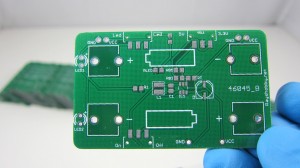
A few weeks ago I received a new batch of the AASaver PCBs at home. I thought, now that I am fairly experienced, it would be interesting to document the process of how I assembled the circuit boards. As you will see below, my assembly setup is manual and is nowhere near the capability of making more than a hundred boards at a time (for that I would outsource the assembly to a professional company). Still, it’s reasonably efficient such that I can enjoy the process of making without losing my mind or temper :).
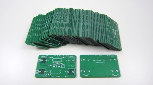
IMG_2264


Step 1. Stenciling

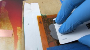
AASaver is designed with all surface mount components. So the first step is to apply solder paste by using a stencil. I used my recently purchased laser cutter to make a stencil out of a Kapton film sheet ordered from Amazon. There are plenty of online tutorials on how to use a laser cutter to make solder paste stencils, so I won’t repeat them here. If you don’t own a laser cutter, you can easily make a stencil using copper sheet with the standard toner transfer and etching method. The tutorial can be found in my previous blog post here. Before I had the laser cutter, I have always used home-made copper stencils, and they work just as good.
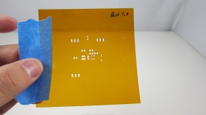
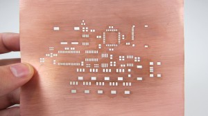
IMG_2265IMG_2300
(Left: stencil made from Kapton sheet; Right: stencil made from copper sheet with home PCB method).

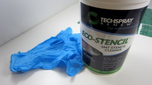
Next, I used old PCBs to make a 3-sided frame that fits the PCB tightly. Then align the stencil with the PCB such that the holes and solder pads match together. I then taped the stencil to the frame for easy lifting up. This allows me to quickly insert and remove a PCB. Since the AASaver board uses fairly big components (0805 and SOT23-6), the alignment does not have to be extremely accurate. Now, before proceeding, you need some tools, including some gloves for hand protection and stencil wipes for cleaning (both are available from from Amazon),
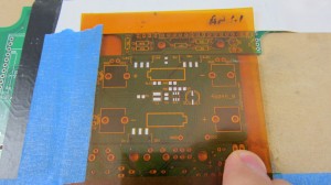
IMG_2266IMG_2273

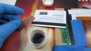
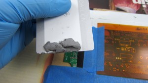
as well as solder paste (which I got from dealextreme.com) and a credit or membership card as applicator. Now, put a sizable amount of solder paste onto the applicator, and then start pressing it down onto the stencil. I usually do two passes: the first swipe leaves a thick layer of solder paste; then the immediate second pass scrapes the excessive paste off the stencil sheet. Use only medium pressure — you don’t need to press very hard. After stenciling, lift up the stencil and remove the PCB from the frame. Check the solder paste on each pad and make sure everything looks ok. If something is wrong, use stencil wipe to clean the solder paste off the PCB and start over.
IMG_2268IMG_2269

IMG_2270IMG_2272

The stenciling step doesn’t take much time. Once you are experienced, you can do it quite quickly: finishing 100 AASaver PCBs took me less than 20 minutes.


Step 2. Populating Components

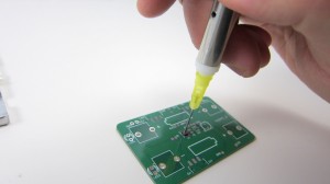
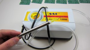
The second step is populating components onto the PCB. This is the most time consuming step and you will probably want to take short breaks in between :). I used to do it with tweezers, which required a lot of patience. Recently I discovered a couple of tools that can help increase productivity quite a bit. The first tool is a vacuum pen. It comes with a portable vacuum pump, two plastic tubes, and a pen with several different needle sizes. This is available on eBay if you search ‘pick and place vacuum pen‘. Be careful that the unit only works with 220V (designed for Chinese market). So in order to use it with 110V, you need a step-up transformer, which I got from Amazon for about 7 bucks. Well, if you plug it directly into 110V power line, there shouldn’t be any damage, the pump probably just won’t start.
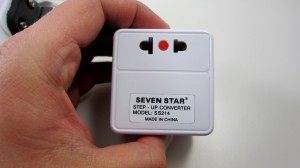
IMG_2274IMG_2275

The second tool I discovered is the SMT feeder. Again, this is available from eBay by searching ‘SMT feeder‘. These are similar to feeders found on automatic pick and place machines, except they are static and do not automatically advance the tapes. I made some labels to help me remember the components on each line.
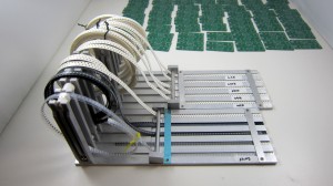
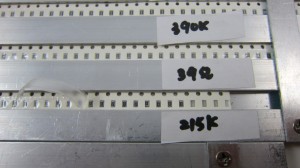
IMG_2276IMG_2277

With these tools, placing components is much easier than using tweezers: I no longer have to dump components out of the tape, or flip components to face up, or spend a lot of time adjusting the orientation of the components. Such a time saver :).

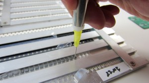
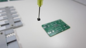
So how do you use the vacuum pen? Notice that on the side of the pen there is a small hole. When you cover the hole with a finger, it creates vacuum suction pressure through the needle of the pen, which allows picking up components. Then when you remove your finger, the air flows through the hole, and releases the component from the needle. I typically use my index finger for this.
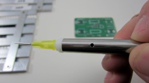
IMG_2279

To demonstrate: first, get the needle close to a component and cover the hole; then pick up the component (as long as your finger covers the hole, the component won’t fall off); finally, carefully approach the PCB, press down the component to where it should be placed, and release the finger. The placing step definitely requires some practice. You can use your other hand to help stabilize the movement and the ‘touch-down’.
IMG_2280IMG_2281

IMG_2282IMG_2283

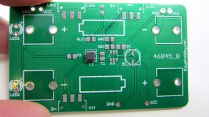
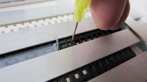
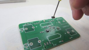
The first few times I used the pen, I was shocked at how poorly the components were placed. I felt it’s a complete piece of junk. But then as I used it more, I realized that I do get more experienced with practising (feels kind of like playing a video game :). Anyways, now I can place components at pretty good speed and accuracy. Practice maker perfect. Note that sometimes you need to change the orientation of a component, and that can be done by simply rotating the PCB around with your other hand. Here is another example of picking and placing an SOT23-6 component, and lastly a picture of the fully-populated board:
IMG_2286IMG_2287

IMG_2288IMG_2284

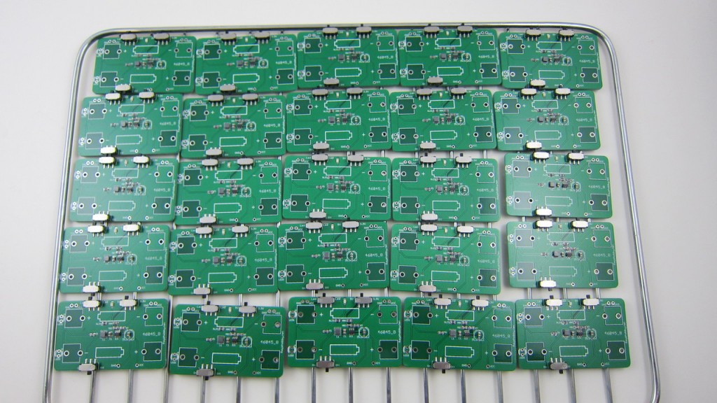
These are 25 boards that have components placed and ready to be toasted:
IMG_2290


Step 3. Reflow Soldering

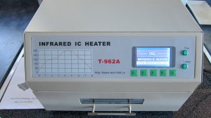
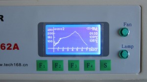
The next step is the fun step, which is the ‘cook’ the PCBs so that the components will be reflow soldered onto the boards. I used to do this step with a toaster oven and a digital thermometer to monitor the temperature. Because I was lazy, I didn’t implement any sort of feedback control. As a result, there were a couple of times that I ‘over-cooked’ the PCBs till they burned and smelled terribly. So I decided to buy a real reflow oven. The one I purchased is model T-962A from eBay (which used to sell at ~$400 but is now more expensive). Note that its sister model T-962 is cheaper but also has a much smaller soldering area.
IMG_2241IMG_2247

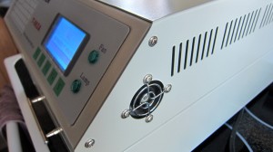
This reflow oven does the basic stuff: it lets you select a pre-programmed reflow temperature profile, or program a custom profile if you want; it follows the selected profile quite accurately, by using an internal infared heating element, a cooling fan, and microcontroller-based feedback control; it also has a glass slit window on the front to allow you to monitor what’s happening inside the drawer. The user manual even describes how to use it to solder double-sided PCBs, which I haven’t tried yet.
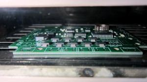
IMG_2242IMG_2245

The oven also has its drawbacks: the standard profile takes 7~8 minutes to finish one cycle of reflowing, which is not very fast but perhaps can be accelerated using a custom profile; also, the heating is not entirely uniform — the area close to the boundary is cooler than the center, causing PCBs placed nearby the boundary to be poorly soldered. But once I am aware of these limitations, I can cope with them.

One important thing to keep in mind is that you should place the reflow oven outdoors. Even with lead-free solder paste, the exhaust from the reflow process is unpleasant at least, and probably harmful to your health. So keep it out of your living area.

Once the reflow is done, I get back a tray of freshly baked ‘cookies’. Satisfied 🙂 Take a close look at the PCBs and see if everything looks ok. Especially check if there are any un-soldered paste. If so, put them back and bake again.
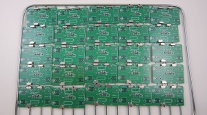
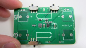
IMG_2291IMG_2293


Step 4. Testing

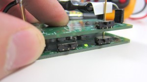
We are not done yet, so don’t bite. The last step is testing, to make sure the circuit board functions as expected. First, perform a quick visual examination. Occasionally components may drift off its position, probably due to insufficient solder paste. These are easy to fix with a hot air gun or even a standard soldering iron. To facilitate testing, I built a simple rig using an existing AASaver PCB and some pogo pins I got from eBay. Here is my setup:
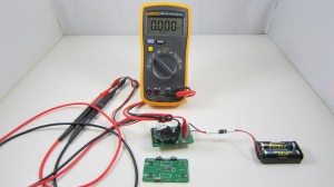
IMG_2295IMG_2298

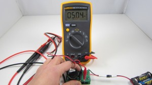
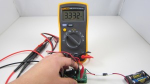
Because AASaver is a regulated voltage booster, the main things I need to test are whether its output voltages are within spec (5V and 3.3V), and whether it maintains the voltage levels (within 5-10% tolerance) under a given current load (320mA). So my test setup includes a multimeter, AA battery holder, and a power resistor to produce the required current load. If the board passes the test (i.e. outputs and maintains the designed voltage levels with load), it will be put into the ‘success’ bin; otherwise, it will be put into the ‘to-be-fixed’ bin for further checking. For a simple board like AASaver, the success rate (yield) is close to 100%.
IMG_2296IMG_2297

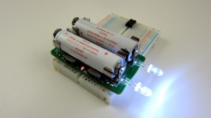
This is a picture of a fully-assembled AASaver in action. It takes two AA batteries, new or used, and can function as an LED flashlight as well as breadboard power supply with switch-selectable 5V and 3.3V output.
IMG_2299

That’s all. Feel free to leave your comments, questions, and suggestions. Thanks!