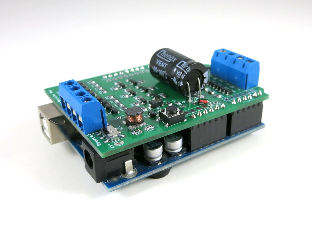
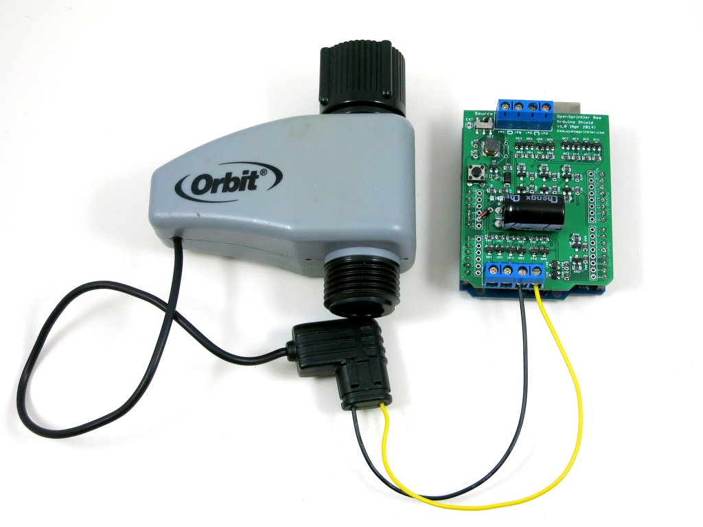
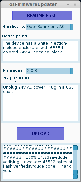
Note: check out our OpenSprinkler DC-powered version, which uses an innovative circuit design that drives sprinkler solenoids using DC-only voltage.
I often get questions about sprinkler valves, so in this post I will explain the basic electric properties of sprinkler valves. If you are designing a sprinkler controller circuit, understanding these properties can be helpful. It’s a common mistake to assume sprinkler valves work with DC voltage. While most valves indeed CAN be powered by DC voltage (see below), they are designed to work with AC voltage in the range of 22VAC to 28VAC. That’s why if you look at a standard sprinkler transformer, the output is usually AC.
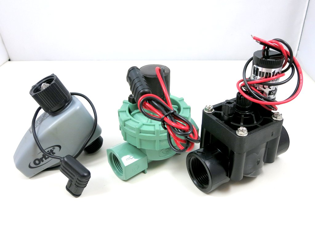
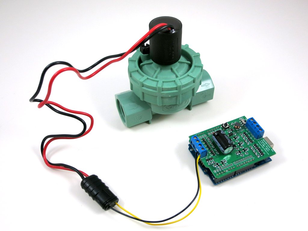
The electric part of a sprinkler valve is the solenoid — it’s a cylindrical-shaped thing screwed into the valve. At the center of the solenoid is a rod supported by a spring. The solenoid has two wires connected to its internal coil. Applying 24VAC on the two wires energizes the coil, and causes the rod to contract into the solenoid. This releases the internal water pressure thus opening the valve, allowing water to flow through the valve. Removing the voltage causes the rod to revert back to its original position. This allows the water pressure to build up internally hence stopping the flow. Because closing the valve relies on internal pressure build-up, it usually takes a few seconds to completely stop the water flow. This also means if your water pressure is too low you may not be able to completely stop the water flow.
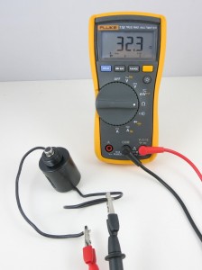
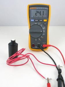
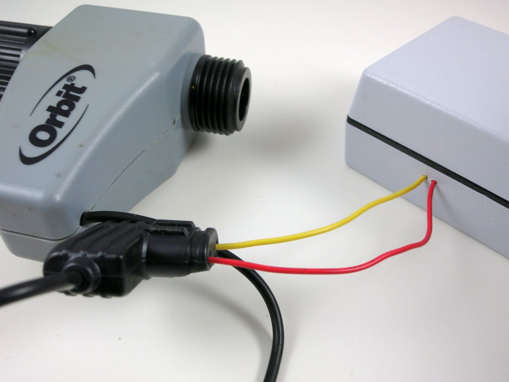
Let’s start by measuring the resistance of the sprinkler solenoid. I have two example solenoids, one made by Orbit and one made by Hunter. According to the multimeter, one measures 32.3 ohm, and the other measures 24.1 ohm. So the resistances are pretty low. If you think about it for a while, you might realize something is not quite right here: if we apply 24V on the solenoid, wouldn’t that produce a 24 V / 24.1 ohm = 1 amp current draw? That’s quite steep. In fact, my sprinkler transformer is only rated 750 mA output current, so it can’t provide enough current to drive even one solenoid?!
The catch is exactly in the fact that sprinkler solenoids are powered by AC voltage. Because the solenoid is made of a coil, it not only has coil resistance but also inductance. When operated on AC power, the inductance produces significant reactance which cannot be ignored. You can read the Wikipage to find out how reactance is calculated, but basically it has to do with the frequency of the input voltage, and the inductance of the coil. Because inductors ‘prevent’ current from changing rapidly, it behaves like a ‘resistor’ under changing current (i.e. AC). The higher the frequency, the higher the ‘resistance’ (i.e. reactance).
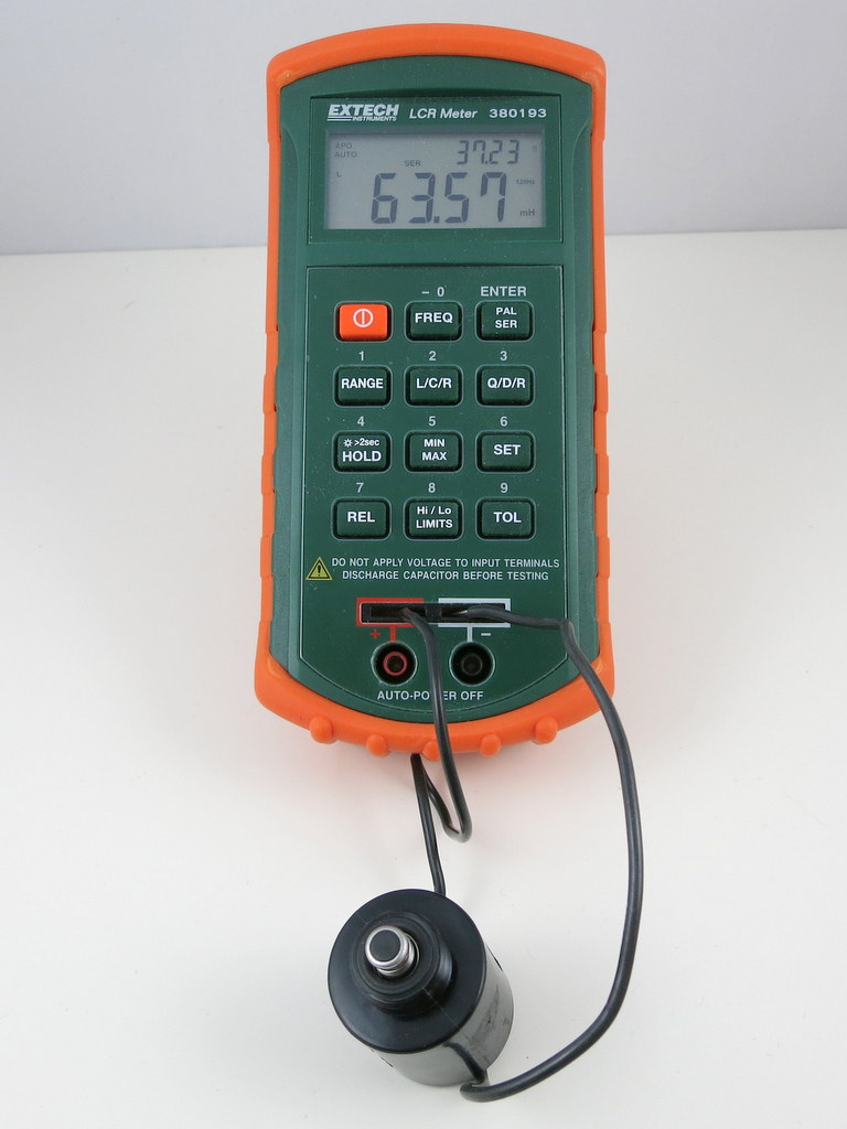
With an LCR meter, I measured the inductance of the two solenoids:
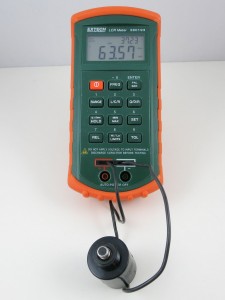
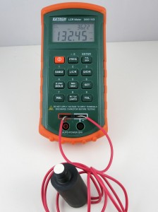
One reads 63.57 mH, the other 132.45 mH. So if we power the solenoids by 24VAC, 60Hz, which is the standard output of a sprinkler transformer, we will get a reactance of:

This, plus the resistance, gives a total impedance of:

Note that the reactance counts into the imaginary part of the impedance. Using complex numbers is just a convenient way of denoting not only the magnitude but also the phase. For example, when you apply a sinusoid voltage on the inductor, the corresponding current is also a sinusoid wave, but with a different phase. Using complex numbers, the calculation can be carried out quite easily.
Now we can calculate the operating current under 24VAC (rms). We only care about the magnitude, so the current (rms) would be:

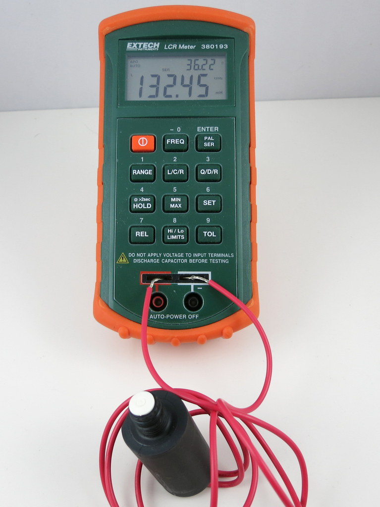
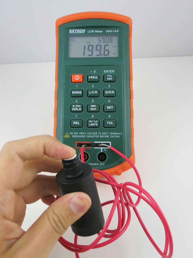
OK, so this is getting closer to the reality. But 0.6 amp current still sounds high. What is missing? Well, remember that when the solenoid is activated, the rod will be attracted into the solenoid, and that can change the inductance significantly. So let’s re-measure the inductance with the rod pushed in:
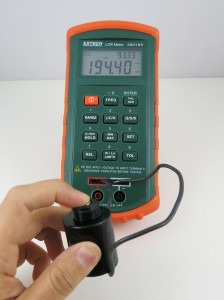
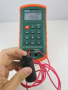
Indeed the inductance jumped from 63.57 mH and 132.45 mH previously to 194.4 mH and 199.6 mH respectively. OK, now if we redo the calculations, we will find out that the correct reactance is:

and current (rms) os:

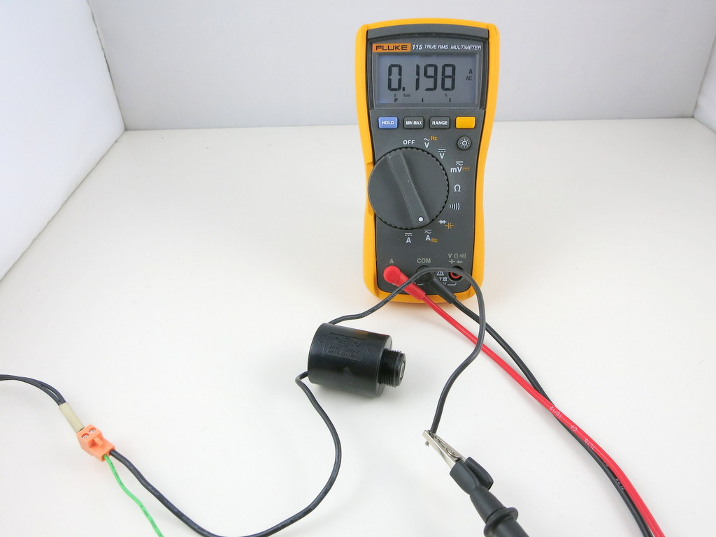
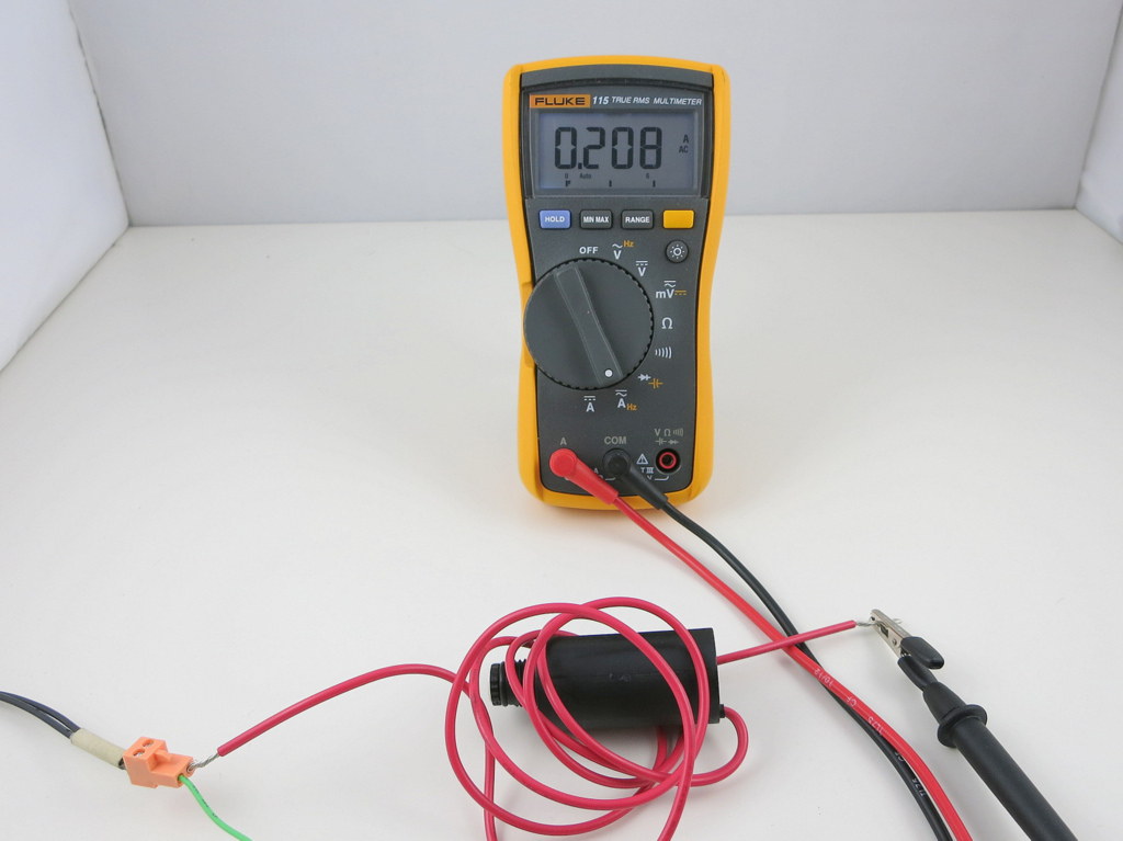
The resulting current is about the same on the Hunter solenoid. So this roughly matches the electric specification of a typical sprinkler valve. It’s actually still a bit off: if we measure the actual AC current flowing through the solenoid:
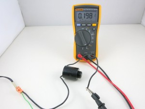
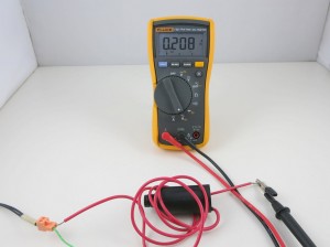
The readings are about 0.2 amp. I suspect the difference comes from the measurement of the inductance. On my LCR meter, which can measure inductance at two frequency levels: 120 Hz and 1 kHz, I find that the inductance is measured differently under the two frequencies. Because the actual operating frequency of the solenoid is 60 Hz, and my meter cannot measure 60 Hz, the inductance I am getting is probably somewhat off. That should explain the difference between the calculation and the actual current reading.
The 0.6 amp current we calculated above probably explains the inrush current: when the solenoid is just energized, there is an impulse current that’s typically higher than the holding current. This is because the rod is still out, and hence the reactance is lower, causing a higher current than when the rod is attracted in.
Operating Sprinkler Valves Under DC
Note: check out our OpenSprinkler DC-powered version, which uses an innovative circuit design that drives sprinkler solenoids using DC-only voltage.
From the calculations above, it’s obvious that the coil inductance is important at limiting the operating current when the valve is powered under AC. What about if we power the valve under DC? Obviously we shouldn’t use 24VDC, because that would draw too much current (0.75 to 1 amp). If you search online, you will find plenty of posts talking about powering sprinkler valves using 12VDC. This actually works well in general. Using 12VDC has advantages in that 12VDC power adapters are cheaper and much easier to find; the circuit design is simpler, and you can use the same circuit to interface with other DC devices like relays and motors. In contrast, 24VAC power circuits are more complex and you can’t use the same circuit to directly interface with DC devices.
However, you should be aware that because the sprinkler solenoid’s resistance is pretty low, the operating current under 12VDC will be relatively high, around 400 to 500 mA. This more than doubles the 200 mA operating current (rms) under 24VAC. Also, the coil will heat up more, and this potentially shortens its life. For example, under 12VDC, the Orbit valve above will dissipate 12 * 12 / 32.3 = 4.5 Watt; whereas under 24VAC, the same valve only dissipates 0.2 * 0.2 * 32.3 = 1.3 Watt (note that only the resistive portion dissipate power, inductive portion does’t).
Again, the issue is that under DC there is no reactance, so the coil’s inductance plays no effect at limiting the current. What if we reduce the voltage further to 9VDC, in order to reduce the operating current? After all, the solenoid only needs 200mA holding current to remain activated. Unfortunately that won’t work: I’ve tried powering solenoids with 9V, and I can’t get the valve to reliably energize. The problem is that 9V is not sufficient to provide the required inrush current, so the rod cannot get fully attracted in. However, if the rod is already in, 9V is sufficient to hold the solenoid activated. So if you really want to make it work with 9V, you need a circuit that can provide a high impulse voltage; then once the solenoid is activated, you can lower the voltage to reduce the current (hence power) consumption. A possible solution is to use a boot converter (very much similar to circuits for latching solenoids) to provide an impulse high voltage, but this comes at the cost of increased circuit and software complexity.