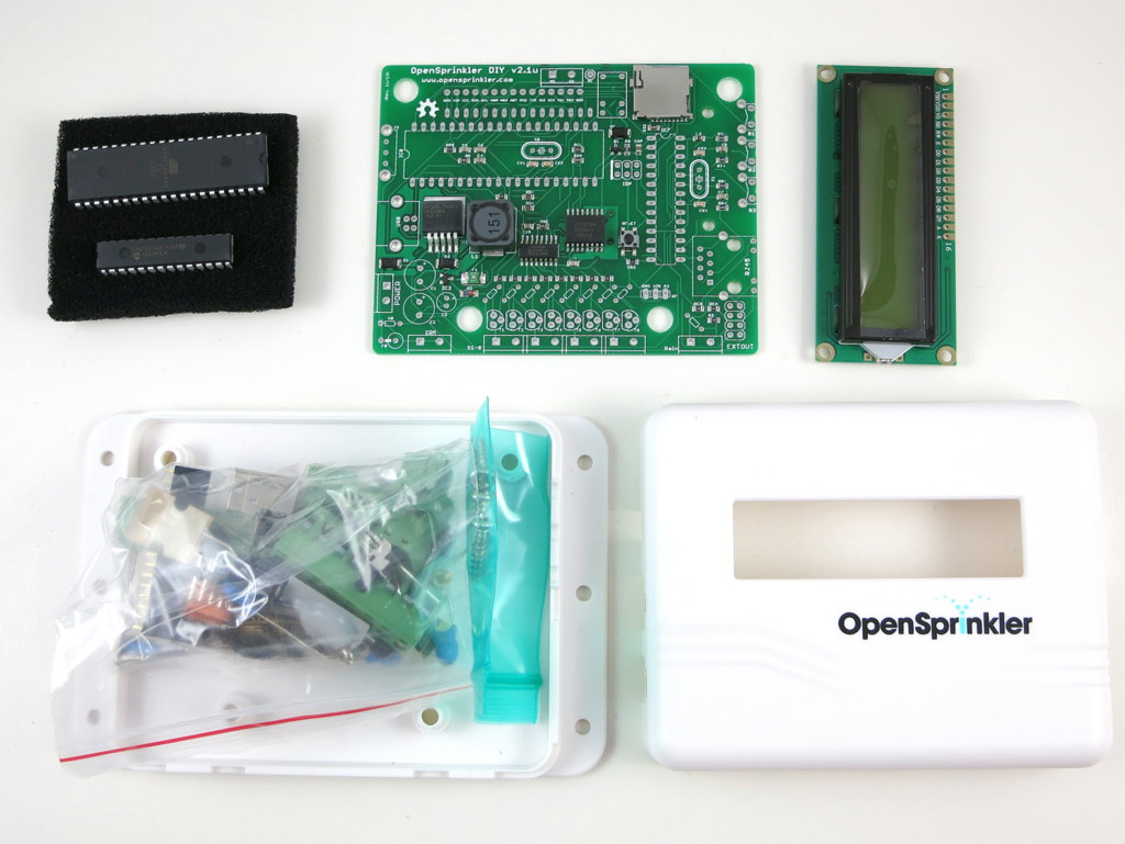
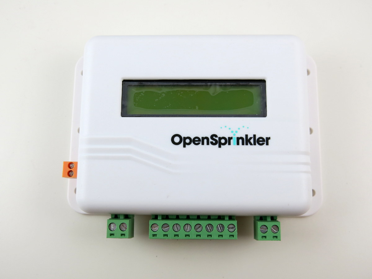
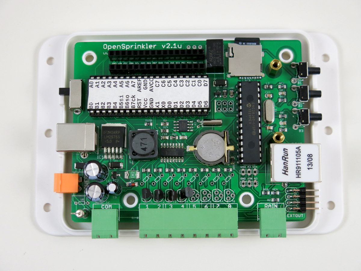
Great news, OpenSprinkler v2.1u semi-assembled DIY kit has now been officially released and available immediately for purchase at the Rayshobby Shop! This version marks a major upgrade from the previous DIY kit v1.42u. With ATmega644 MCU, microSD card slot, and injection-molded enclosure, it not only brings the DIY kit up to speed with the fully assembled v2.0s, but it actually strives to be a little better (hence the migration on the version number) 🙂
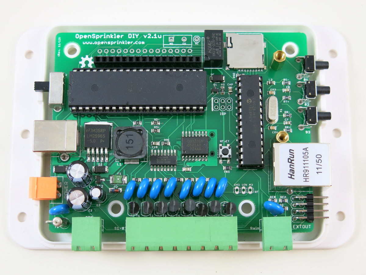
In particular, it adds a mini-relay for general purpose switching (similar to the one on OpenSprinkler Beagle), changed the 24VAC terminal to an orange colored one with different pin spacing, and increased MCU frequency from 8MHz to 12Mhz. It also uses a USBasp bootloader built-in on the ATmega644 MCU for firmware flashing (while all previous versions use a separate ATtiny45 chip). The USBasp bootloader significantly improves the firmware upload speed, and is therefore very helpful if you are making frequent changes to the firmware. These changes are all described in the prototype sneakpeak preview post. Finally, the MCU is pre-loaded with the latest firmware 2.0.3 with several new features compared to the previous firmwares.
Another notable change is that v2.1u is the first semi-assembled DIY kit which comes with a partially assembled circuit board with through-hole components. I’ve designed it this way to help reduce the amount of soldering you have to do, while still let you enjoy the process of building, assembling, testing, and hacking the circuit. It’s a first-time experiment, so I will keep my fingers crossed.
In any case, if you’ve been waiting for OpenSprinkler DIY kits, go grab one quickly before it’s gone; if you already own an OpenSprinkler or have heard of OpenSprinkler one way or another, I would appreciate if you can help me spread the word. Thanks!
This is a special note that we are offering a Thanksgiving promotion for OpenSprinkler 2.0s: use coupon code turkeyday8 to get 8% off regular price. The coupon is only valid on the four days of Nov 27 to 30. The coupon can be applied in the ‘View Cart’ link. If you are thinking of getting an OpenSprinkler 2.0s, either for yourself or as a gift for friends, there is no better time than this! 🙂
OpenSprinkler Beagle kit is available for purchase at Rayshobby Shop.
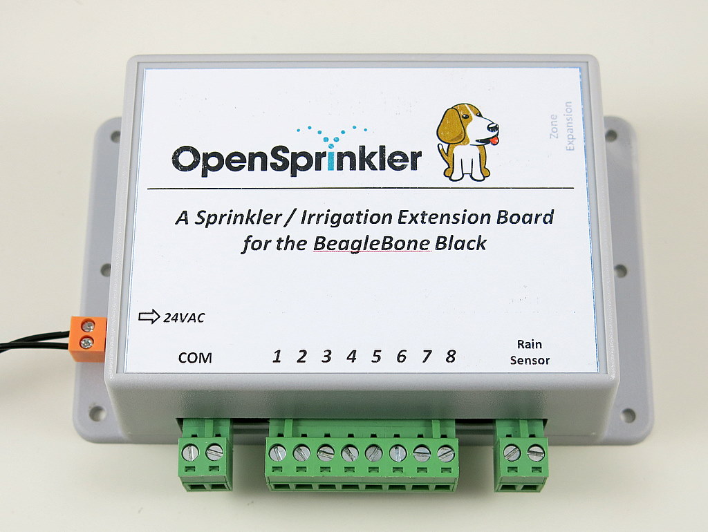
Following the sneak-peak preview, I am excited to announce that OpenSprinkler Beagle (OSBo) v1.0 is now officially released! OpenSprinkler Beagle is an open-source sprinkler / irrigation extension board for the BeagleBone Black. It uses four GPIO pins to control an unlimited number of sprinkler valves. Using this board, you can easily convert your BeagleBone Black into a low-cost, web-connected smart sprinkler controller. You can use online weather data to help regulate sprinkler water time, and remotely change settings and programs when you are traveling away. Best of all, it’s an open-source project — you are welcome to tinker with the hardware and/or software to create your own customized sprinkler controller.
The idea of OpenSprinkler Beagle came from the OpenSprinkler Pi, which is a sprinkler extension board for the Raspberry Pi. Since OpenSprinkler Pi was released earlier this year, it has been a very popular product. Over time I’ve received requests from users to develop a similar board for the BeagleBone Black. While the BeagleBone Black is similar in nature to the Raspberry Pi (i.e. both are low-cost embedded Linux boards), it offers some interesting benefits such as a large number of GPIO pins, build-in analog pins, build-in eMMC, microSD card slot (i.e. smaller profile). faster CPU etc. Undoubtedly it makes sense to develop an OpenSprinkler variant for the BeagleBone Black.
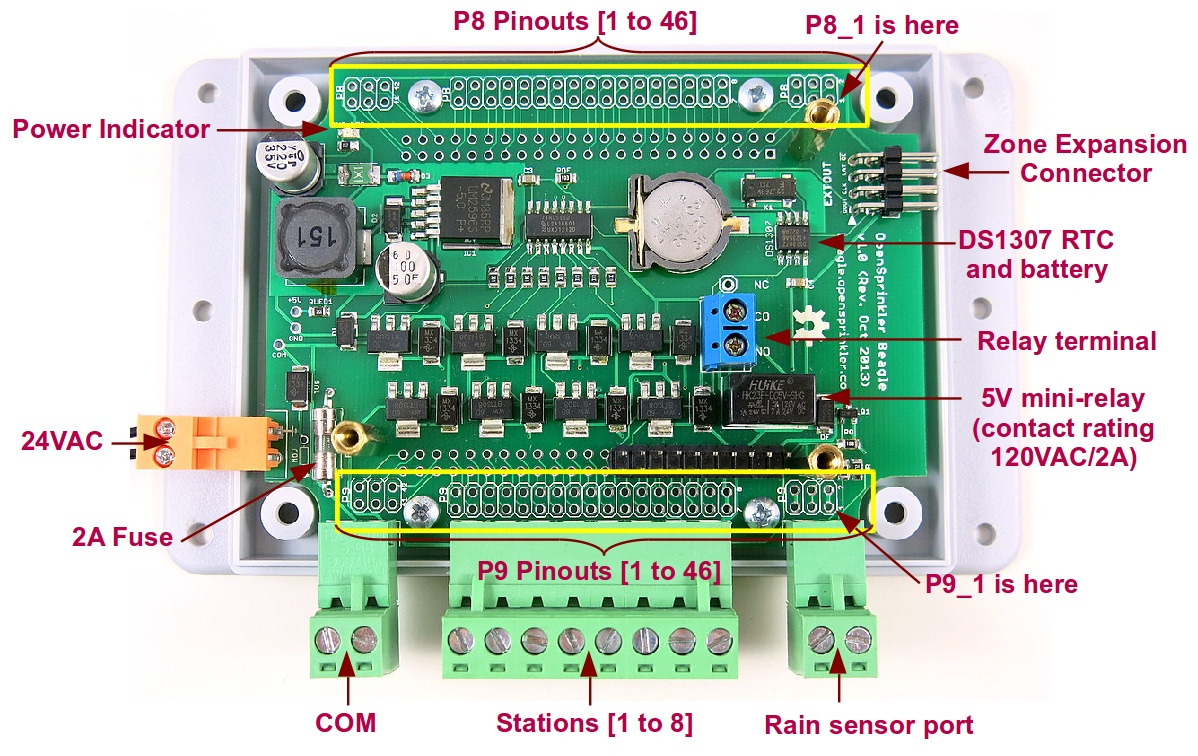
The hardware design of OpenSprinkler Beagle is similar to OpenSprinkler Pi: it contains a 24VAC to 5VDC switching regulator, shift register, triac, DS1307 RTC with CR1220 battery, zone expansion board connector. It also currently shares the same enclosure as OpenSprinkler Pi. But it also offers several improvements, specifically:
Added a total of 10 bidirectional TVS for protection against transient voltages: one for each of the eight stations, one for the 24VAC port, and one for the rain sensor port.
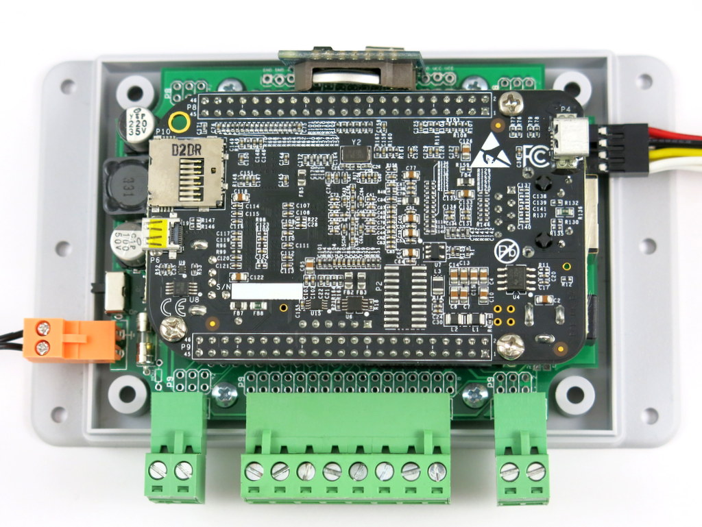
The BeagleBone Black is now plugged down into OSBo, and all GPIO pins are mapped out to the pinout area.
Added a 5V mini-relay for more general-purpose switching. The relay has a contact rating of 120VAC / 2A. It can be used for switching low-power lighting, or garage doors etc.
The 24VAC terminal block is changed to orange color with 3.96mm pin spacing. This helps prevent incorrect connection to other terminal ports. There is also a solder-on 2A fuse on the 24VAC line.
Added a rain sensor port with pull-up and current limiting resistors.
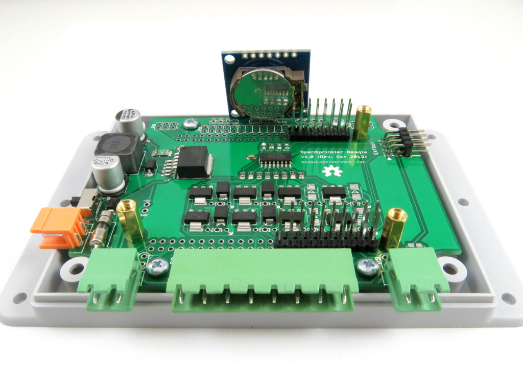
Below is an annotated diagram that shows the various components of the board:
OpenSprinkler Beagle Homepage
Below I am going to give a very brief overview of the hardware and software setups. For details, please watch the tutorial video above, and visit the official OSBo homepage at http://beagle.opensprinkler.com.
Hardware Setup
The hardware is pretty easy to set up. The kit comes with an assembled OpenSprinkler Beagle circuit board, enclosure, screws, terminal blocks, and extra pin headers in case you want to map out additional GPIO pins. In addition, you need to provide a BeagleBone Black, a nano-size WiFi dongle, and a 24VAC sprinkler transformer (these are not included in the kit and need to be purchased separately). The board makes use of the first 2×10 pins on port P9 of the BeagleBone Black for interfacing with shift register, RTC, rain sensor port, and mini-relay. Plug in the BeagleBone Black into OSBo, connect the 24VAC power, plug in the common (COM) wire and individual station wires, and that’s it. The interface is the same with other sprinkler controllers. If you have a rain/freeze sensor, you can connect it to the rain sensor terminal.
Software Setup
Follow the recent update on OpenSprinkler Pi, the software setup for OSBo has also been made a lot easier. Specifically, I’ve created a SD card image with pre-installed software. Download the image, burn it to a microSD card, pop it in to your BeagleBone Black, and you are ready to go. The pre-configured SD card runs a Ubuntu operation system (default user name ubuntu, password temppwd), and sets Dan’s interval_program to start by default. As soon as the system has booted and is up online, you can open a browser and type in http://x.x.x.x:8080 (where x.x.x.x is your BeagleBone’s IP address). This will bring up the interval program’s web interface. The interval program has a rich set of software features, such as setting multiple sprinkler programs, preview programs, run-once program, manual operation, logging, rain delay etc. The details are all explained in the user manual of the interval program.
The SD card has also pre-installed Samer’s mobile web app, which provides a nice front-end for mobile devices such as pads and phones. It is available at http://x.x.x.x/sprinklers.
In addition, there are three demo programs installed in the /home/ubuntu/demos/ folder. There is a self-test program, a relay test program, and a Google Calendar-based sprinkler program, which makes use of a Google Calendar for scheduling water events. I’ve received many good comments regarding the Google Calendar-based program — while it looks simple, it’s quite convenient to use and very suitable for the less technical minded people.
Since the software is pretty much all adapted from OpenSprinkler Pi, feel free to refer to the OpenSprinkler Pi documents if anything is unclear. I will try to make the OpenSprinkler Beagle website more self-contained, and it will have to be polished over time.
Naming
In the previous post, I asked for naming suggestions. Thanks to everyone who made comments there. After careful thoughts, I’ve decided to use the full name OpenSprinkler Beagle, and short name OSBo. Particularly, the short name OSBo is picked because it goes well with OSPi (OpenSprinkler Pi), is easy to distinguish with OSBee (openSprinkler Bee), and Bo is a name of a dog. So overall I consider this to be the top choice.
Thanks for reading this post. If you are interested in buying the OpenSprinkler Beagle, we have a limited number of kits immediately available, at the first link below. Feel free to leave comments and suggestions below or at the Rayshobby Forum.
An OpenSprinkler Pi user Michael Wilson sent me this nice illustrated document he wrote about setting up OpenSprinkler Pi and the mobile web app. He successfully installed OpenSprinkler Pi to replace his previous Toro controller. The document has somehow slipped out of my mind and has been sitting in my mailbox for a few months. I should have posted it when I received it! Anyways, thanks Michael for sharing it with us!
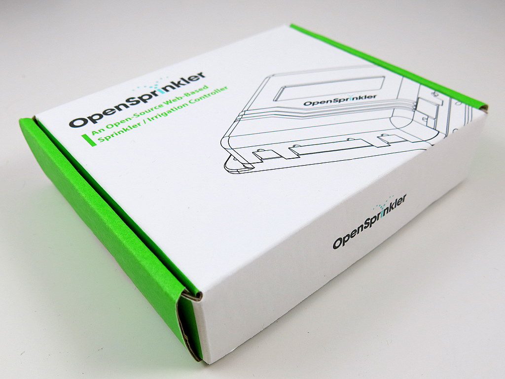
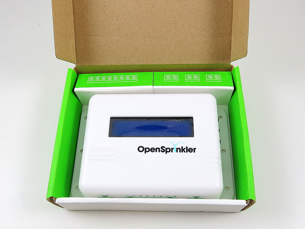
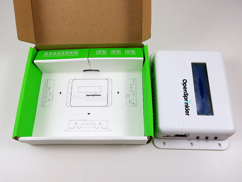
This post is a direct update of the post I wrote in September during my visit to SeeedStudio. Today I received the official sample of the OpenSprinkler paper box. Check the photos below. Very cool!
The paper box was designed by SeeedStudio, and hopefully it will give OpenSprinkler a more professional touch.
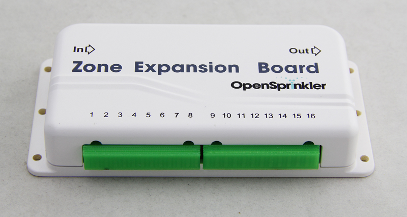
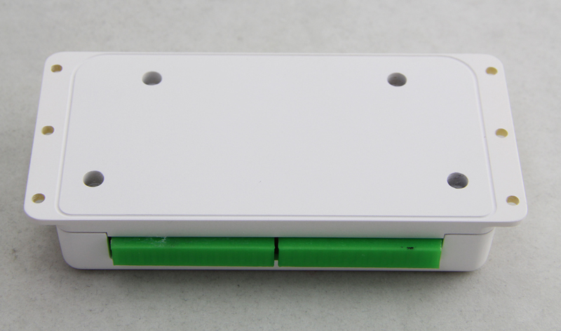
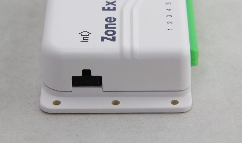
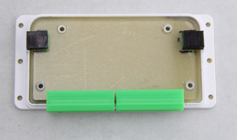
The other piece of news is that we’ve finalized the new zone expansion board enclosure design. This is going to be injection molded soon. Below are pictures of the 3D printed prototype. The style follow the OpenSprinkler injection molded enclosure, so they will have a consistent look. The new design allows 16 stations per zone expansion board, yet the board size is roughly the same with the current 8-station zone expansion board. So it’s really really compact. This will probably become available in the first quarter next year.
NOTE: OSPi v1.4 requires either a microSD card or a low-profile SD card (due to the limited space in the enclosure). A microSD card adapter for RPi is included in the kit.
The image is compressed from an existing OSPi installation that contains Dan’s interval_program, Rich’s sprinklers_pi program, Samer’s OpenSprinkler mobile app, and the Google Calendar-based scheduling program. Download it, burn it to an SD card, and pop it in to your Raspberry Pi. Then you will be ready to go right away. No more pulling your hair or banging your head against the wall (well, hopefully :))!
The process to burn the image to an SD card is the same as burning a raspbian image to SD card. If you’ve used Raspberry Pi before, you’ve probably done this already, maybe even multiple times. If not, you should check the detailed online instructions here: http://elinux.org/RPi_Easy_SD_Card_Setup
Here is a quick summary:
Decompress the image file to your computer.
Insert an SD card (4GB or above). Make sure you back up any important file on the SD card as the procedure below will overwrite the content on the SD card.
Depending on what operating system you use:
On Windows, use the Win32DiskImager software.
On Mac, use the ‘dd’ command in a terminal, for example: sudo dd bs=1M if=name_of_the_image_file of=/dev/partition_to_burn_to
On Linux, the same, use the ‘dd’ command on a terminal, for example: sudo dd bs=1M if=name_of_the_image_file of=/dev/partition_to_burn_to
VERY VERY IMPORTANT: make sure you have selected the correct drive name (or partition name) to burn the image to!!! If you’ve selected the wrong drive, you might end up wiping out your computer’s hard drive, and I am sure you will be back pulling your hair again!!! Double check before you press enter or click on confirm.
Once the SD card is ready, pop it in to your Raspberry Pi. Since WiFi is not configured yet, you should first connect it directly to your router using a wired Ethernet cable. Alternatively, if you are a Linux user, insert the SD card to your computer, and you directly edit the WiFi SSID and password in file /etc/network/interfaces on the SD card (not your computer!). This way when you pop it in to RPi, it will automatically connect to your WiFi network.
In your home router’s configuration page, find out the IP address assigned to the Raspberry Pi. Next, open a browser, and type in:
http://x.x.x.x
where x.x.x.x is your Raspberry Pi’s IP address. You should see a page with further instructions, such as setting up time zone, WiFi etc. If you can see this page, congratulations, you’ve succeeded!
Dan Kimberling’s interval_program is set as the default program to run on start-up. Type in the following url in a browser: http://x.x.x.x:8080
(again, x.x.x.x is your Raspberry Pi’s IP address) and you should see the web interface of the interval_program.
The OpenSprinkler mobile app is also pre-installed to the SD card, which is available at: http://x.x.x.x/sprinklers
You can also switch to run Rich Zimmerman’s sprinklers_pi program on start-up. To do so, ssh (or use a monitor and keyboard) to your Raspberry Pi (the system uses the default user name pi and password raspberry) and run the script in a terminal: sudo /home/pi/select_program. Once you’ve switched to the sprinklers_pi program, you can access its web interface at the same http://x.x.x.x:8080.
These have all been explained in the one-page instruction. For questions, comments, and suggestions, please post them at the Rayshobby Forum: http://rayshobby.net/phpBB3. Thanks!
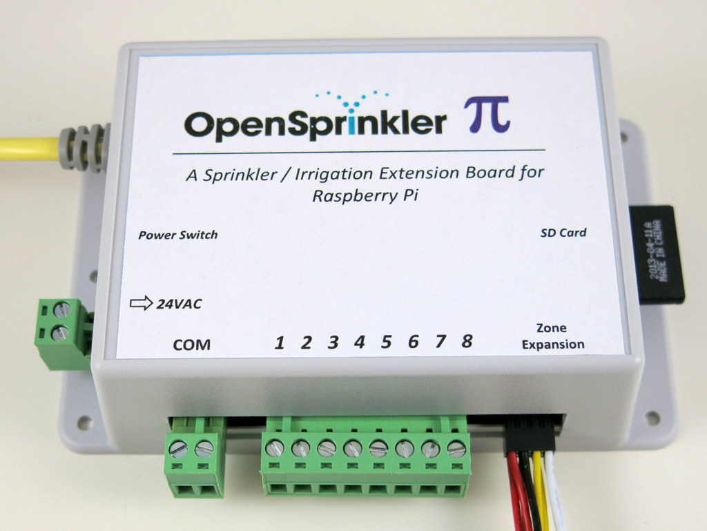
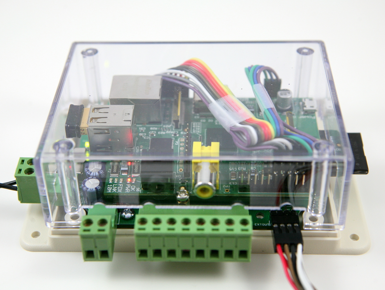
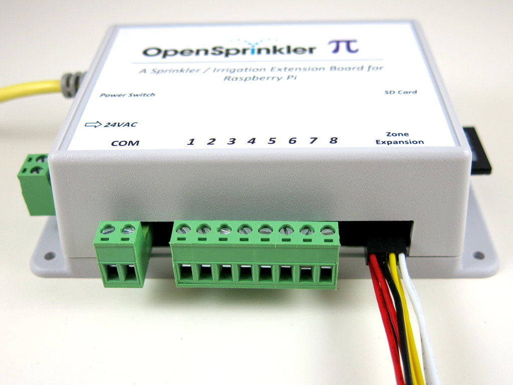
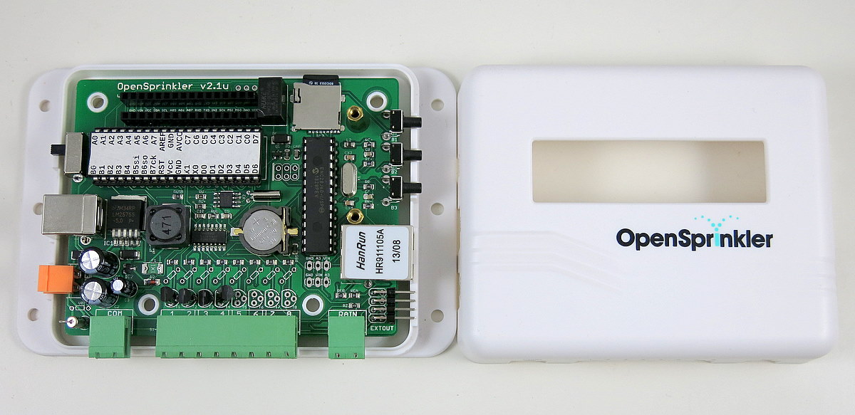
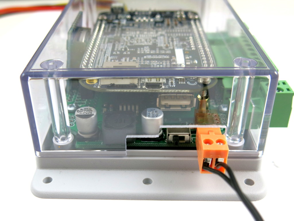
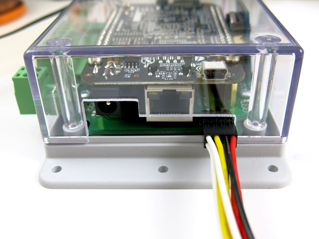
We’ve just got a new batch of enclosures for OpenSprinkler Pi (OSPi). The dimensions are the same with the transparent cover enclosures we’ve been using so far, but it’s now in solid color (light gray) and comes with a printed label on top. The picture on the left below shows the new enclosure. For comparison, the picture on the right is the current one with transparent cover.
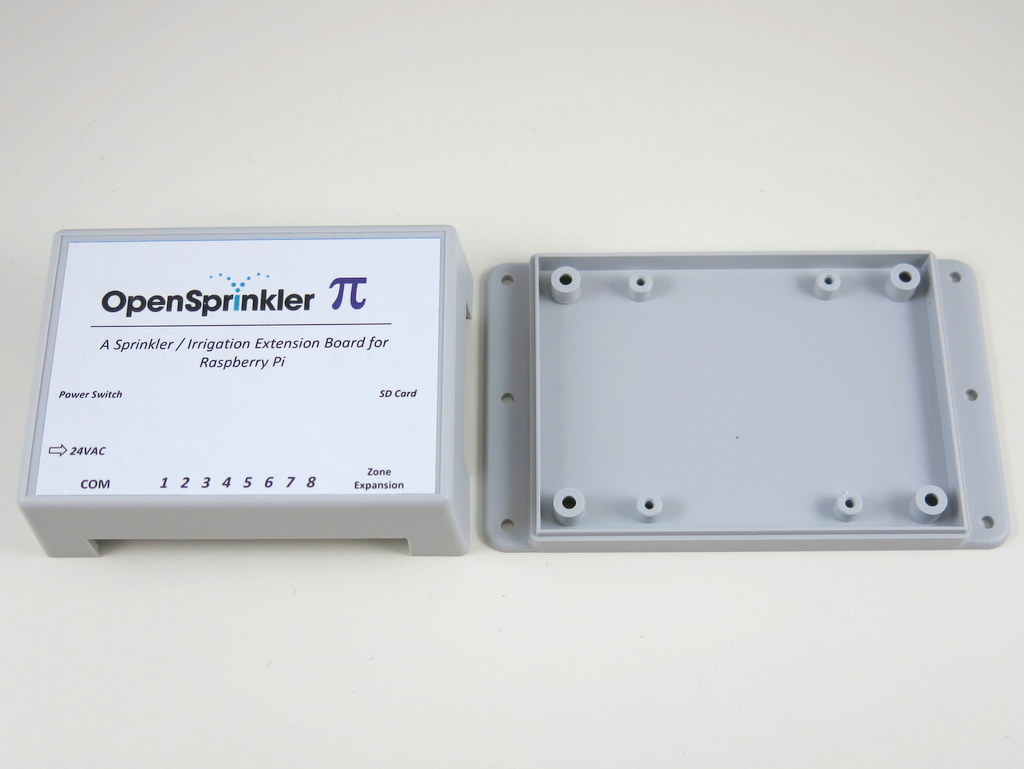
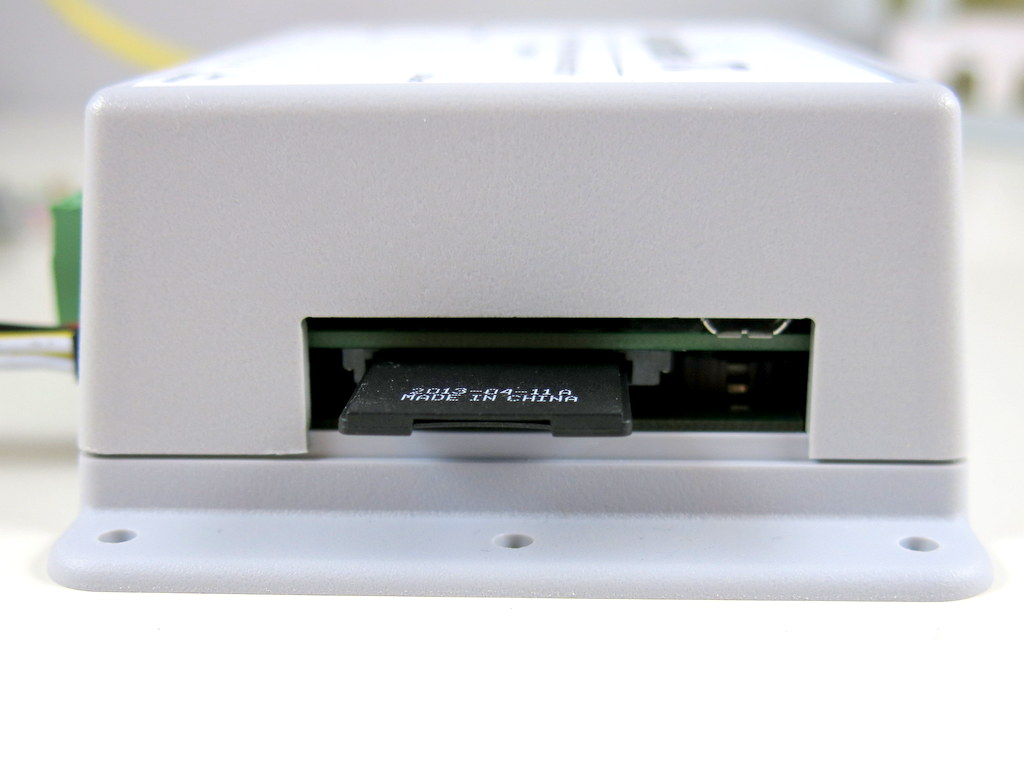
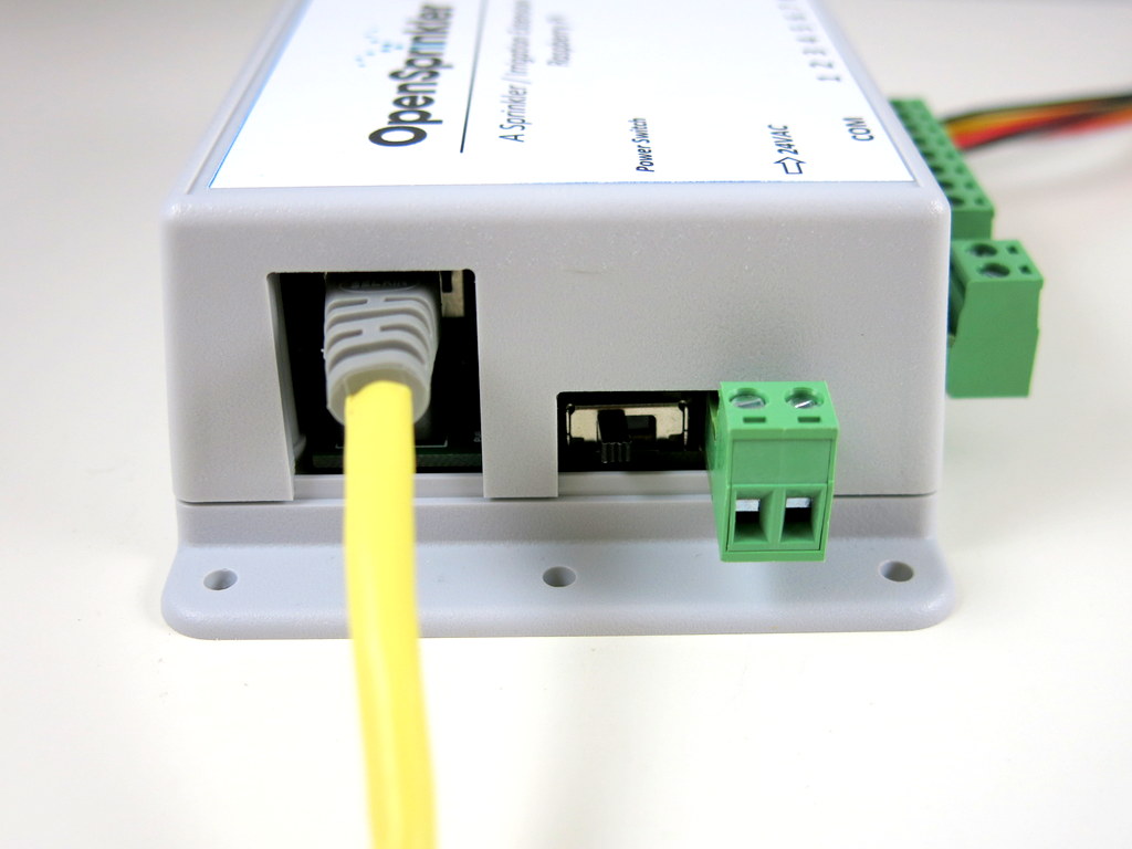
The label makes it clear where each connector is located. Also, an additional cutout is included in the left-hand side to allow an Ethernet cable to pass through. This will be useful for anyone who wants to stick with wired connection. The pictures below show the two pieces of the enclosure and the assembly from three different sides:
A little bit history about this: the transparent cover was originally adopted because it’s exactly the same enclosure used for Arduino-based OpenSprinkler DIY kit. There is a good reason to share the enclosure as it saves cost of having to making a new design. Now as the OpenSprinkler DIY kit will soon step up to use the injection molded enclosure, it’s time to give OpenSprinkler Pi a dedicated ‘shirt’, so that the cutouts can be more tailored to OSPi.
Anyways, the new enclosure option is compatible with all existing versions of OSPi. If you’ve purchased an OSPi in the past and prefers the new enclosure, you can purchase it separately from the store link here. Thanks!
Continuing from yesterday’s post, today’s sneak peak preview is for OpenSprinkler DIY v2.1u — the solder-and-assemble-yourself version of the OpenSprinkler.
This is the first major upgrade of the DIY version since v1.42u. The main differences compared to 1.42u are:
The microcontroller is upgraded to ATmega644, doubling the flash and RAM size of ATmega328.
Switching regulator changed to LM2596S-5.0, which is beefier than MC34063.
Added microSD card slot, space to fit MOVs, and pin headers to fit an RF transmitter.
Enclosure is changed to use the injection molded case.
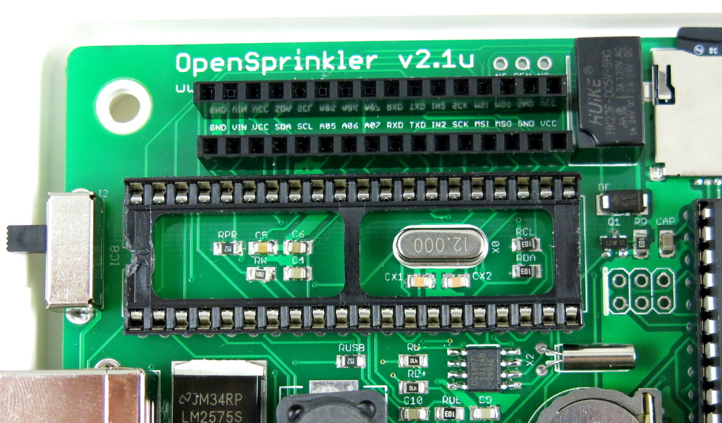
The design is pretty much similar to the fully assembled OpenSprinkler 2.0. To make it easy to solder, some components are been changed to use through-hole version, notably the ATmega644 microcontroller, the ENC28J60 Ethernet controller, triacs, and several capacitors. Due to the limited space (particularly as the through-hole ATmega644 is so much larger than the previous ATmega328), it’s not possible to keep all components in through-hole style. In fact, even with surface mount, I ended up using the trick of hiding some components underneath the microcontroller, as shown in the picture below:
In addition, the microSD card slot and the LM2596S regulator are not well-suited for hand-soldering. So unlike v1.42u, which uses all through-hole components, v2.1u will be in the form of hybrid SMT and through-hole — The SMT components will be pre-assembled, and the through-hole components will be soldered by users. Strictly this should be called semi-assembled OpenSprinkler.
While the hybrid solution may sound disappointing to DIY lovers, I figured this is still an interesting compromise, as it leaves sufficient flexibility for anyone who wants to tinker with it. For example, the mcu can be easily upgraded to ATmega1284, which is pin compatible with ATmega644 but has 128KB flash and 16KB RAM. Also, the triacs can be replaced by transistors or MOSFETs to interface with DC devices. So we will see if there is enough interest in this new experiment. If you are looking for an all through-hole version, I have to say 1.42u remains the best solution.
Now, why is this version numbered 2.1? Is it jumping ahead of the fully assembled OpenSprinkler 2.0? That’s right — there are some minor improvements / changes from 2.0, so I figured a new revision number is necessary to tell them apart. Here are the main differences:
First, the ATtiny45 (which functions as a USBtiny programmer) has been removed, partly to save space, and partly to simplify the design. Instead, the ATmega644 will be flashed with a USBasp bootloader, which allows itself to function as a USBasp programmer in bootload mode. This will take away 2KB of flash memory space, but on the plus side, it eliminates one chip, and the transfer speed of USBasp is actually noticeably faster than USBtiny. Additionally, using ATmega644 to directly handle USB tasks (thanks to the V-USB library) makes it possible to add USB serial functionality. As a result, you can do serial communication to debug the code, without any external USB serial converter. So it’s win-win-win 🙂 The details can be found in my previous blog post about USB HID-class Serial Communication for AVRs.
Next, the 24VAC port has been changed to use a new type of screw terminal that has smaller pin spacing and orange color. This will prevent users from accidentally plugging it into the COM or Rain Sensor port, which would damage the controller. A 2amp fuse on the 24VAC line, and a current limiting resistor for the Rain Sensor port has also been introduced for added protection. Finally, a relay has been added on digital pin D14, to allow general-purpose switching need, such as opening garage door, and power line device etc.
Due to these changes, particularly the USBasp bootloader (which requires ATmega644 to run at 12MHz instead of the current 8MHz on OpenSprinkler 2.0), it’s necessary to use a new revision number to avoid confusion.
In any case, the prototype has been verified and I only identified a couple of minor changes to fix. Otherwise it’s pretty much ready to go. It should be available for purchase within a month. So stay tuned!
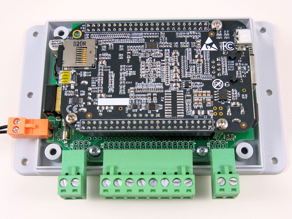
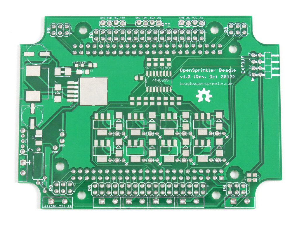
A lot of prototype PCBs arrived over the weekend. Among them is my long-waited OpenSprinkler Beagle — a sprinkler / irrigation extension board for the BeagleBone Black. Cool, time for some prototyping actions!
The design of OpenSprinkler Beagle largely follows OpenSprinkler Pi (OSPi). As usual, the board contains a 24VAC to 5VDC switching regulator, shift register, triacs, terminal blocks, and zone expansion board connector. It provides 5V power to the BeagleBone Black, uses 4 GPIO pins (specifically P9_11, 12, 13, 14) to interface with the shift register, and SDA2/SCL2 to interface with the DS1307 RTC. Since the BeagleBone and RPi are similar in size, I can reuse the same enclosure as I’ve been using so far.
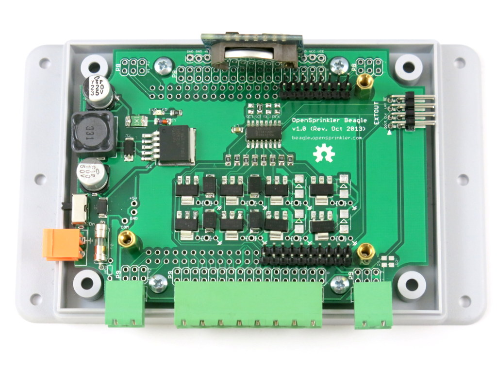
There are also several changes and improvements. First and probably the biggest design change is that the BeagleBone Black is now oriented face-down, and it plugs directly to the extra long male pin headers as you can see on the pictures above and below. In contrast, on OSPi, the Raspberry Pi is oriented face-up, and connection from RPi to the board is through a pair of 8-pin and 3-pin cables. The biggest advantage of the face-down design is that it saves the cables, and there is now some extra space in the upper-half of the enclosure, making it possible to add additional modules. To make it easy to reuse the available pins on the BeagleBone, I’ve also mapped out all the 46 pins on ports P8 and P9 to the pinout area.
I actually wanted to use the same design for OSPi, but it’s more tricky because RPi uses male pin headers, which means the extension board will have to provide female pin headers. I haven’t been successful at finding extra long female pin headers, but I will keep looking.
Among the other changes: the 24VAC port is now using a new type of terminal block that has different pin spacing and color with the others. This will reduce the chance of accidentally plugging 24VAC into the COM or rain sensor port, which has happened before. Speaking of rain sensor port, yes, there is now a rain sensor terminal — it takes one extra GPIO pin, but there are plenty of GPIO pins on the BeagleBone, so who cares 🙂
Also, I’ve added a 2A fuse, and nine 48V bidirectional TVS (transient-voltage suppressor) — one for the power in, and one for each of the eight zones. This will provide some level of protection to the circuit during power surges and lightening. In the past I’ve used MOVs (metal-oxide varistors). Those are pretty cheap, but they are bulky and have to be hand-soldered since they are through-hole components. TVS is a bit more expensive but can be easily automated using pick-and-place machines.
Also, the analog-digital converter (ADC) has been removed since the BeagleBone has built-in analog pins. As sort of an experiment, I also removed the on-board DS1307 RTC, but instead added pin headers to plug in an external RTC module, as you can see close to the top of the PCB. This was done as an experiment to empty out some space on the PCB to allow future expansion. But it turns out to be not very successful, because the module actually takes quite some space and makes it difficult to close the top cover.
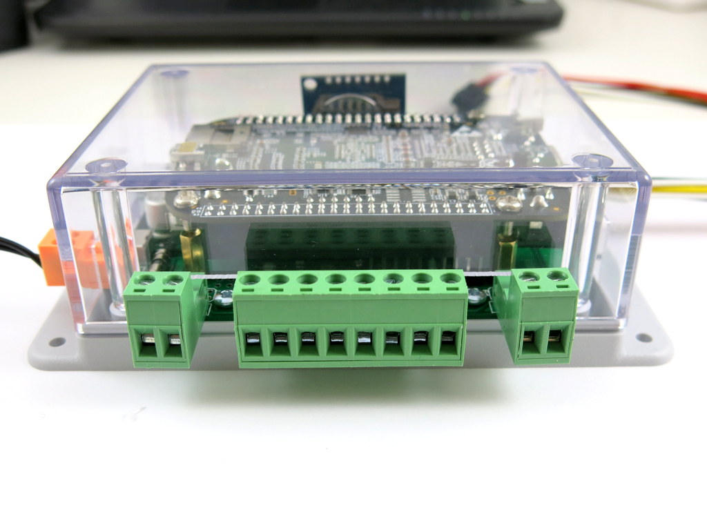
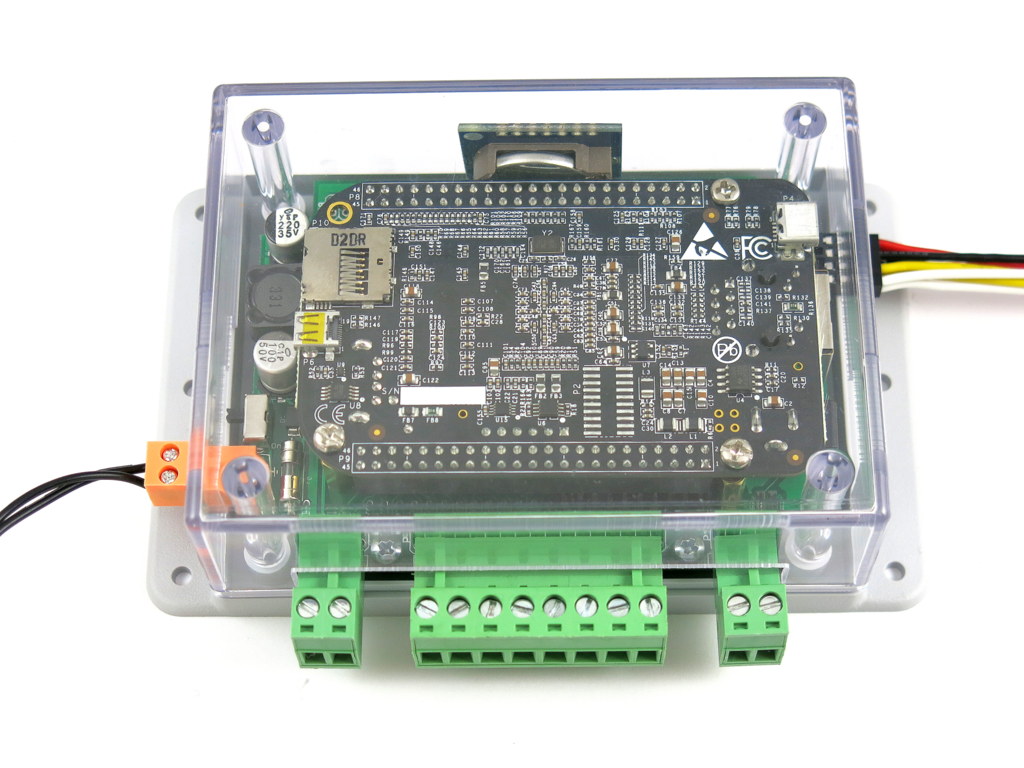
Here are some additional pictures of the assembly:
I quite like the overall design. There are a few minor changes I want to make before the official release. For example, the 100uF capacitor is currently too close to the BeagleBone’s USB port, and it needs to be moved further away. Also, I can make the PCB color black to match the color of the BeagleBone Black. By the way, I learned from the forum that some users want to use the sprinkler controller to control garage doors. I figured it’s it’s pretty easy to add a relay on the board for general-purpose applications. So I am gonna try to add that too.
Naming
What would be a good abbreviated name for OpenSprinkler Beagle? Since it’s designed for the BeagleBone Black, I could call it OSBBB, but I want to distinguish it from another product I am working on — the OpenSprinkler Bee (OSBee). OSBBB and OSBee are too close with each other to pronounce. One possibility is to call it OS-Bo, which would put it nicely in a series with OS-Pi and OS-Bee. If you have better suggestions, feel free to leave a comment below. Thanks!
As I am getting more experienced with the TM-240A pick and place machine (in the following I will call it the PNP machine, as in PNP transistors 🙂 ), I’ve been thinking of ways to improve productivity. One obvious way is to panelize PCBs, meaning to assemble multiple copies of the PCB onto the same board. This can help greatly reduce the overhead time of stenciling and PNP loading time. I have to admit, I’ve never done PCB panelization before. I did search online and found various tutorials, but it’s unclear to me how to exactly indicate the ‘V-cut’ layer to the PCB manufacturer.
But I found an easier route. Recently I’ve been ordering PCBs directly from a Chinese company called 深圳嘉立创 (http://www.sz-jlc.com). I got to know this company very randomly, actually through watching the beginning clip of the SparkCore Kickstarter video. The company has a very streamlined PCB manufacturing process, where you can track each step of the PCB making, all the way from drilling, to printing layers, to etching, to optical inspection, to solder-mask and silkscreen printing, to testing, and to shipping. It’s completely amazing (except the website only has Chinese version…). Anyways, when you order PCBs from their website, apparently you can specify how you’d like to panelize your PCBs. You don’t need to panelize the PCB yourself in Eagle (which I haven’t learned how to do yet), but you just need to describe your panel design (like 2×3, 4×4 etc.), and they will do the panelization free of charge. Isn’t that awesome?
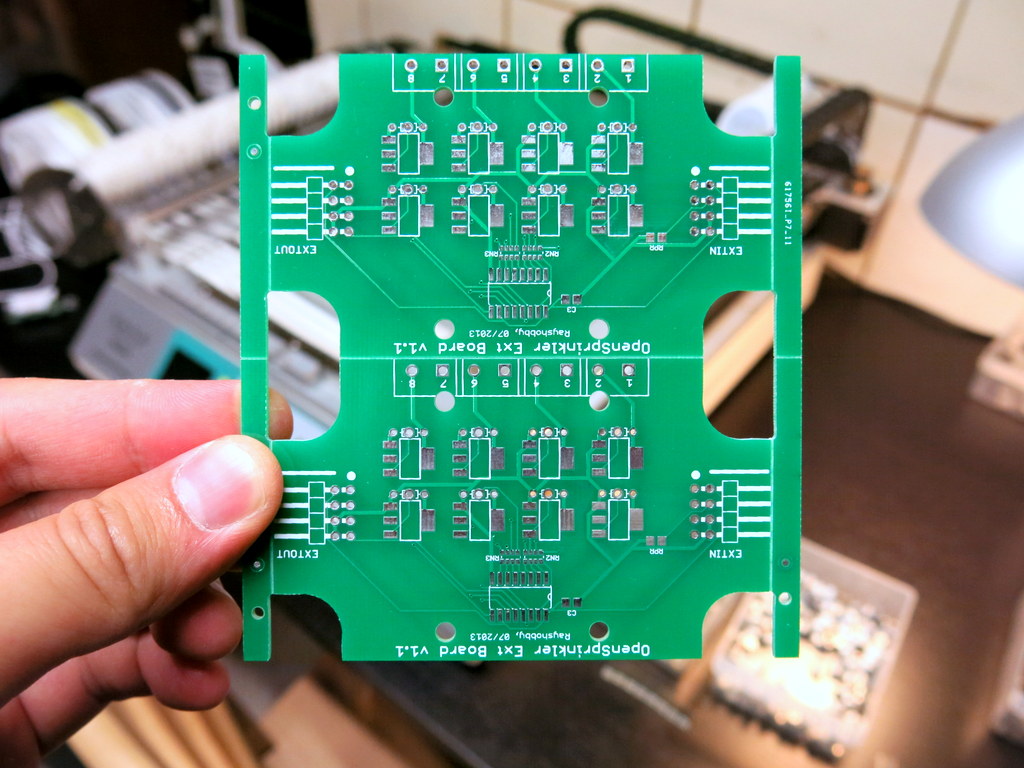
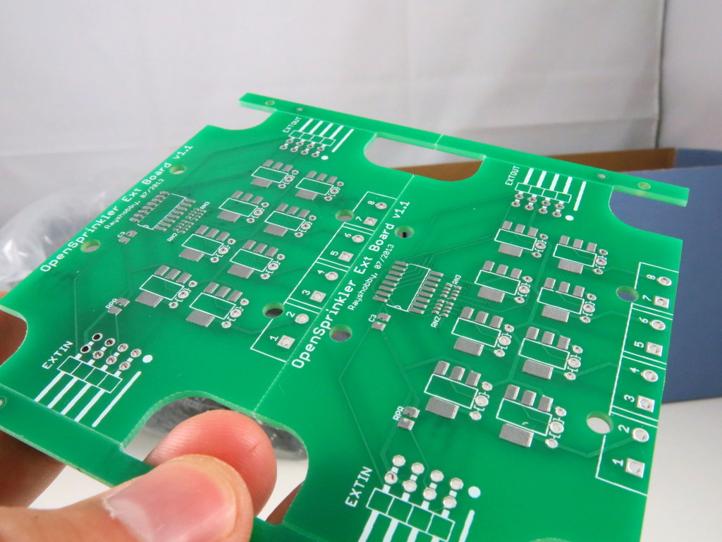
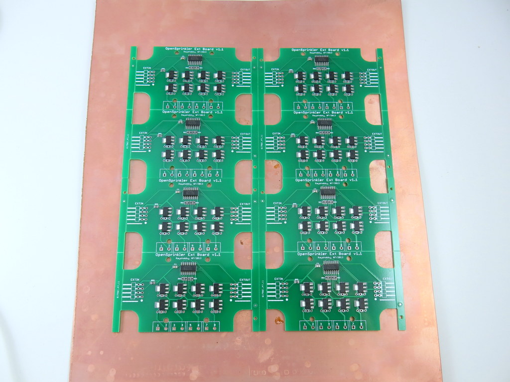
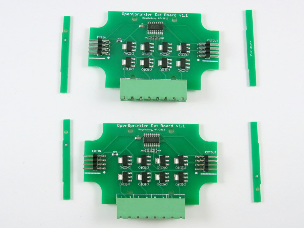
Since this is the first time I’m ordering panelized PCBs, I wanted to be careful. So I ordered a very simple board — the OpenSprinkler Zone Expansion board, with the simplest panelization — 1×2. And the image on the left below shows what I received. Very neat. I also asked them to add an extra 10mm border on each side, and fiducial points (these I paid extra for). Since the board is not rectangular shaped, the panel comes with routed edges on the curved sections, and V-cuts on the straight lines. This way, it can be easily de-panelized by simply snapping each board off along the straight edges. Pretty awesome, especially considering I didn’t have to do anything in Eagle to create the panel design 🙂
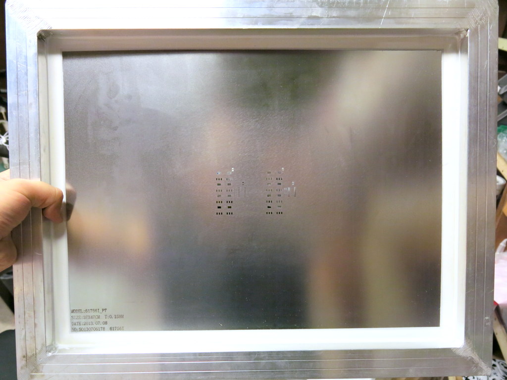
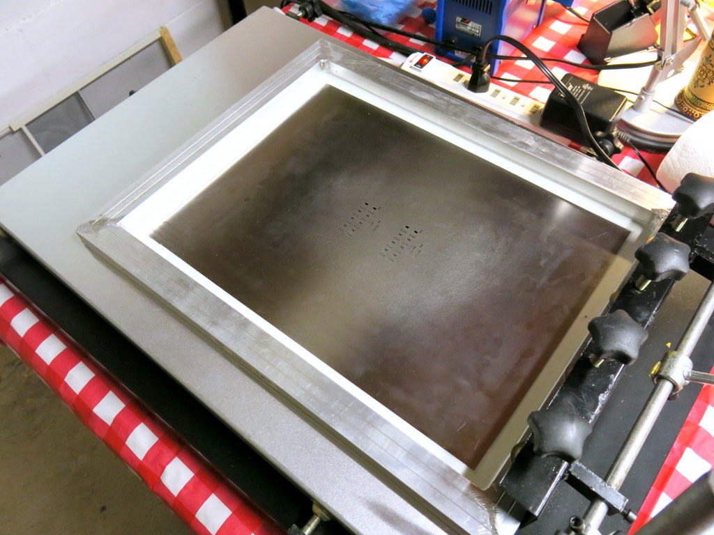
So what’s the picture on the right above? This is also something new to me: apparently when you order PCBs from the company, you can also order a laser-cut solder paste stencil to go with your PCB order. It’s only 10 extra bucks, almost a no-brainer. I ordered one for this particular batch, so I can experiment with it. The stencil is made from a steel sheet, and mounted on a metal frame. It’s quite large (37cm x 47cm), so you will need a stencil printing machine that can handle a board of this size. Fortunately I got a fairly big manual stencil printing machine a while back, so I can put it to good use now.
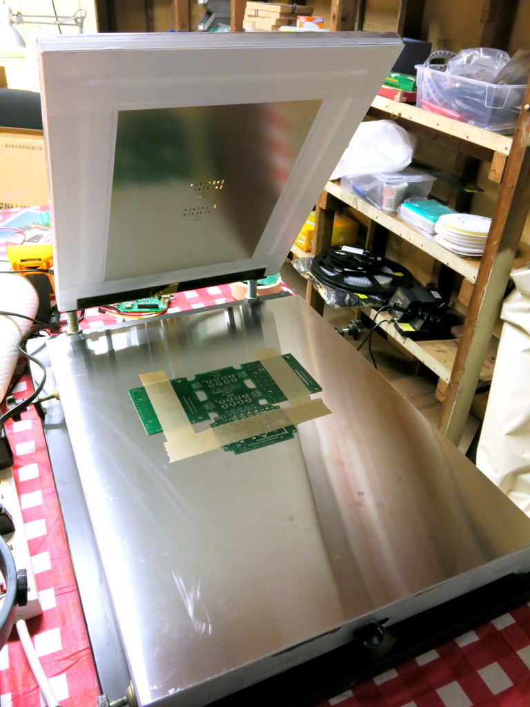
In order to use the stencil, the first thing I did was to mount the stencil frame onto the printing machine. Once mounted, you can easily lift the stencil up and down, to quickly insert and take out stenciled PCBs. Then I aligned the PCB to the stencil holes. This is very tedious — since the stencil is made of steel, which is opaque, there is no easy way to align them. I had to do a lot of trial and error and eventually was able to get them perfectly aligned. Once aligned, temporarily fix the PCB in place by using some tape. Finally, use three old PCBs to make a frame around the center PCB. Then you are all set.
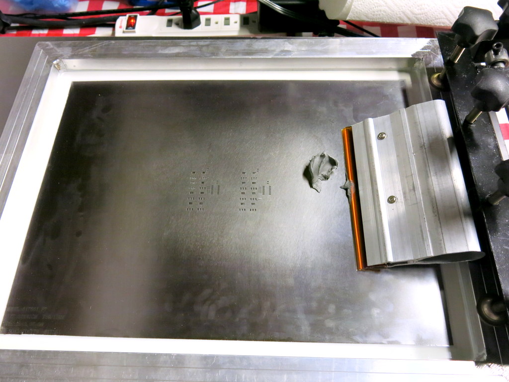
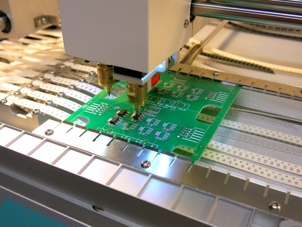
With the stencil printing machine (albeit manual), applying solder paste works like a charm, and is much faster than using my home-made stencils. The stenciling quality is also excellent (see the picture on the right below). Apparently they optimized the stencil design, and created small ‘crosses’ around relatively big (0805 or above) components. This prevents the solder paste from smearing underneath the stencil. Very smart!
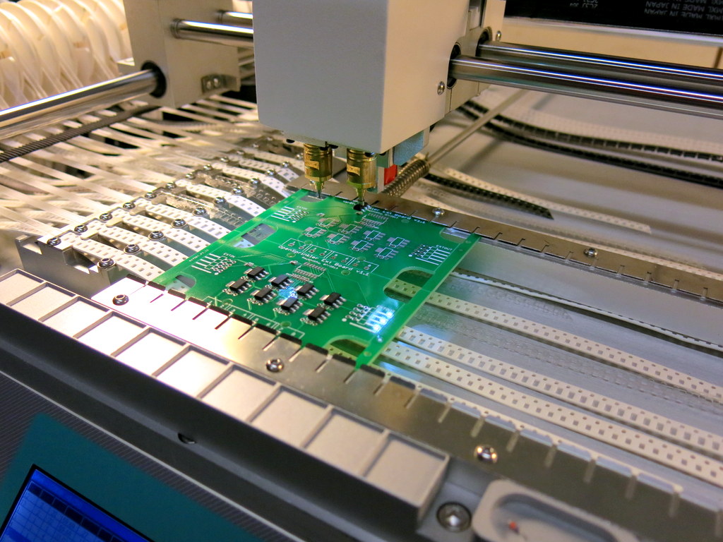
Next step is to populate components. The TM-240A pick and place machine supports PCB panelization. All that I had to do was to open the existing PCB configuration file, and add a new line for each additional sub-board, indicating the amount of shifting from the first sub-board. With this simple change, the PNP machine can now populate twice as many components, a real time-saver!
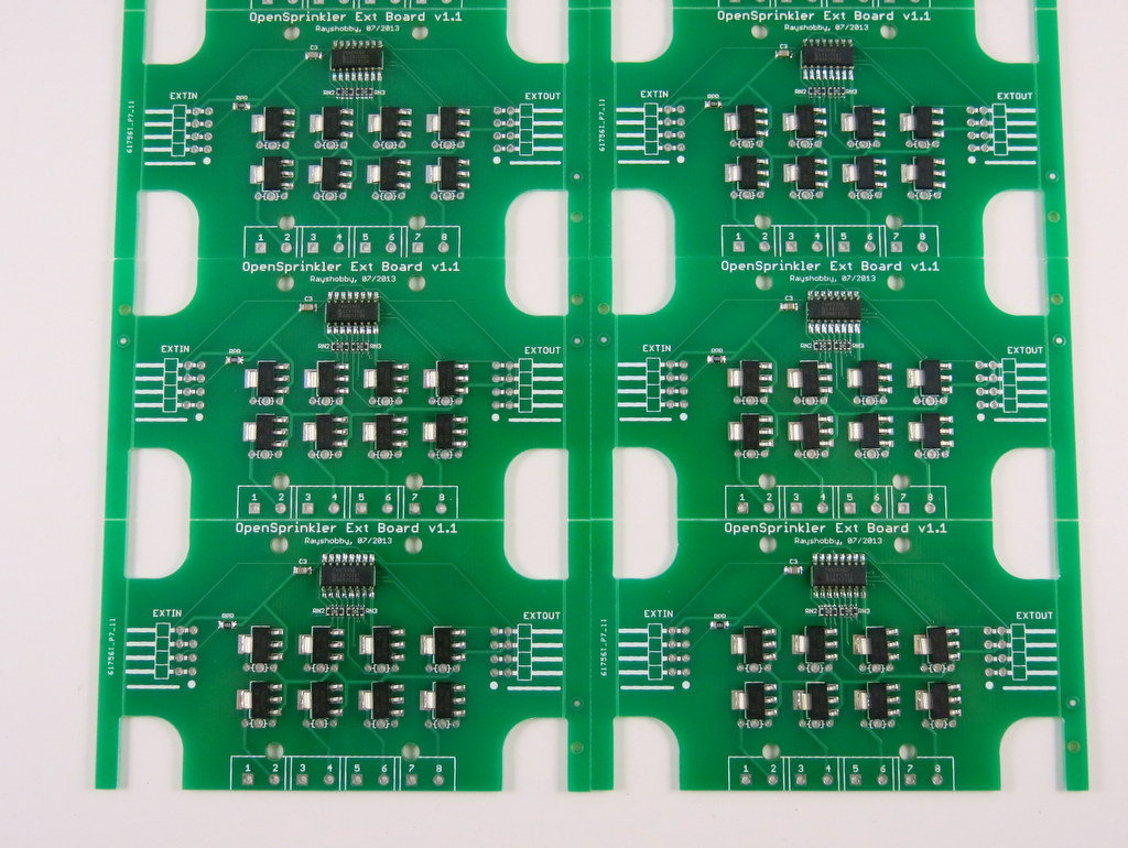
Here are pictures of four boards before and after reflowing. The reflowing quality is pretty good.
Finally, to separate the boards into individual pieces, as I said, just snap the boards along the V-cuts. Use some strength along the cuts, and they should come off pretty easily. Here are the final results (with the through-hole pin headers and screw terminals soldered in place). Neat, isn’t it 🙂
So, to summarize, it takes very minimal effort to make panelized PCBs. First, when ordering PCBs, tell the manufacturer how you would like to panelize the board. They will do the work for you. Next, order a professionally made solder paste stencil with the PCB order. Finally, modify the pick and place configuration file to reflect the number of sub-boards and the shift amount of each. That’s it. Not bad at all!