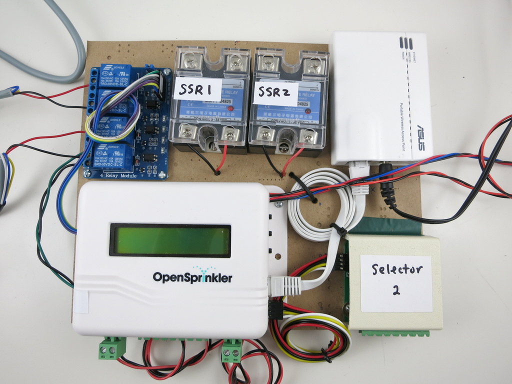
Around Thanksgiving last year, I received a request from a biology lab professor who commissioned me to modify OpenSprinkler to become a custom fluidics controller. The goal is to achieve web-based, programmable control of fluid selector valves, linear actuators, relays, and air valve, to automate a custom biology experiment. I don’t typically accept contract work, but felt this was a very interesting project, as I’m always keen to see wider applications of OpenSprinkler. Also, this particular project fits well with the existing software design of OpenSprinkler, since the control schedules are somewhat similar to typical sprinkler programs.
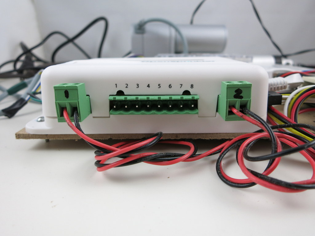
It took me a while to understand the design requirement and how various components worked. The main component is the fluid selector valve, which selects a specific type of fluid from several input fluid streams. The valve has a number of control wires which are normally pulled high. To set a specific position, you basically use open-collectors (one for each wire) to pull a subset of the wires to ground. This is pretty easy to achieve using OpenSprinkler — there are 8 stations on the main controller, each station is a open-collector that controls on wire. By activating a subset of stations, it sets the selector valve to a specific position.
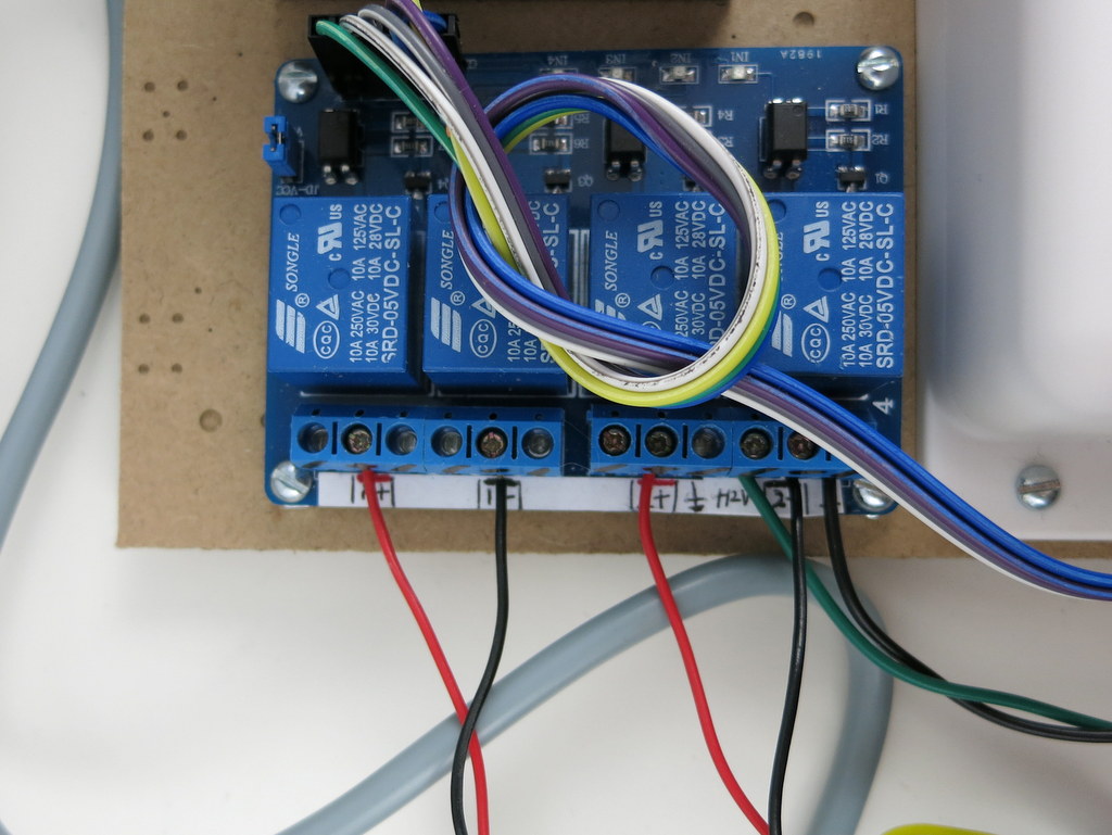
The project also calls for two solid state relays (SSRs) to control 110V pumps. The SSR works with logic level signals, so I used two digital pins to interface with them. Next, there are two 12V linear actuators, and a 12V air valve. Because we don’t want to involve too many different power supplies, we decided to go with a single 12V power supply, which powers the OpenSprinkler, linear actuators and the air valve. OpenSprinkler already has a switching regulator inside that can work with 12V, so that’s not a problem. I then used the built-in relay on OpenSprinkler to switch the air valve. To control the linear actuators, I needed two high-power H-bridges. The way linear actuators work is that they each have two wires — apply positive 12V on the two wires, the actuator will start to extend; reverse the polarity, the actuator will retract. This is similar to how a motor works, and it’s typically done through an H-bridge. Because the linear actuator can draw up to several amps of current, I decided to use a 4-channel relay board (instead of MOSFETs) to implement two H-bridges. So four additional digital pins are used to toggle the 4 relays.
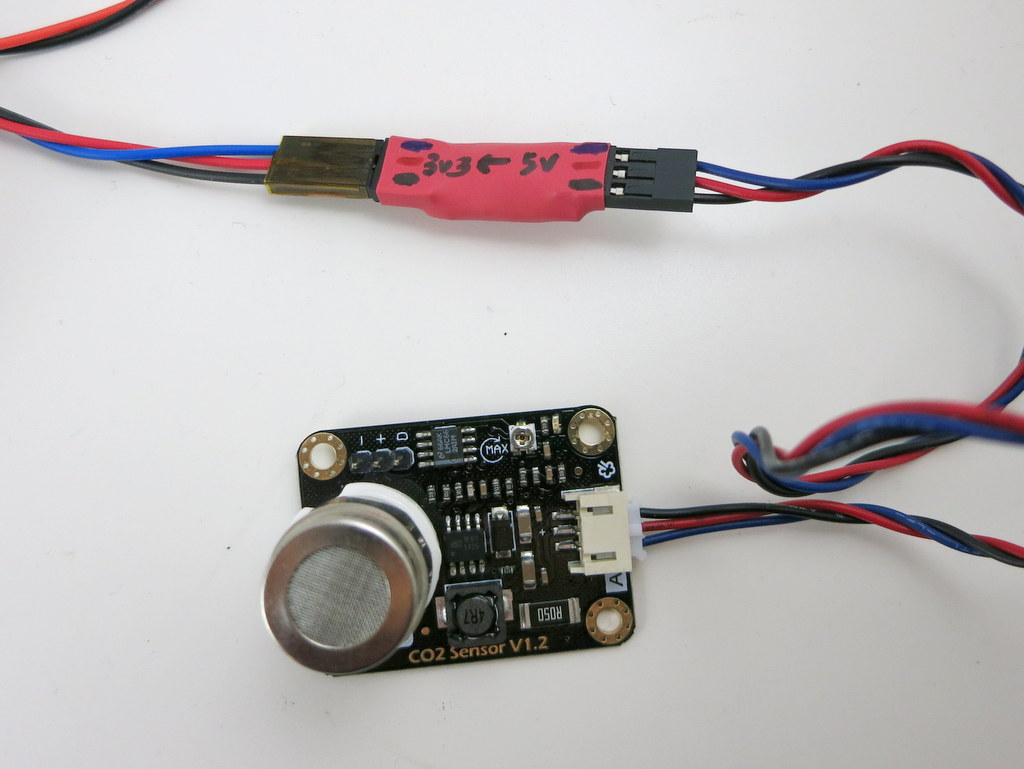
The right image above shows a CO2 sensor. It is used to conditionally open the air valve at the end of the experiment. The idea is that the air valve will only need to be open if the CO2 level is above a certain threshold. I didn’t have chemicals to generate CO2, but had plenty of soda at home, so it was quite easy to create varkous CO2 levels to help test the sensor 🙂
Then as soon as I started working on the software, I realized that the control schedules are actually not entirely the same as sprinkler programs. Specifically, each schedule contains multiple entries, where each entry indicates the status of every component and the time the status will last. It’s kind of like: upon starting the program, the components should be in status A, B, C; after 15 minutes, they will change to status D, E, F; and so on. So I decided to overhaul the existing OpenSprinkler firmware, and rewrite it with a new program data structure. The end result is that each program contains multiple entries. For each entry, you specify the status (such as on/off) of every component, and the duration (i.e. how long the status lasts). In a sense this can also be used to schedule sprinkler programs, and it’s actually very powerful, because it allows you to set almost arbitrary schedules, including scheduling multiple stations to open at the same time, and scheduling the same station to water multiple times within a program. So maybe once day I will make it an alternative OpenSprinkler firmware.
Anyways, it was a really fun project. I didn’t have very good documentations about the work, but I did shoot a couple of video clips. Check them out below.
Back in early December last year, we introduced a new feature in OpenSprinkler Firmware 2.1.1 that allows OpenSprinkler to directly talk to remote power sockets. With this feature, you can use OpenSprinkler to not only switch sprinkler valves, but also switch powerline devices such as light, pump, heater, fan. While it’s a powerful feature, it is after all a wireless solution so it’s not the most reliable — sending wireless signals to remote power sockets is prone to interference and is limited by distance and barriers (e.g. walls, floors) in between.
If you still prefer using relays, whether because it’s more reliable, or because it’s the classic way, there are plenty of choices. I’ve often received questions about how to use OpenSprinkler with a relay. The easiest solution is to get a 24V AC relay. Then you can wire it up as if it’s a sprinkler valve — when OpenSprinkler turns on the corresponding station, the relay is activated, and that turns on the device connected to the relay. Because AC relays are not as common as DC relays, they tend to be more expensive. Here I list three choices I’ve found:
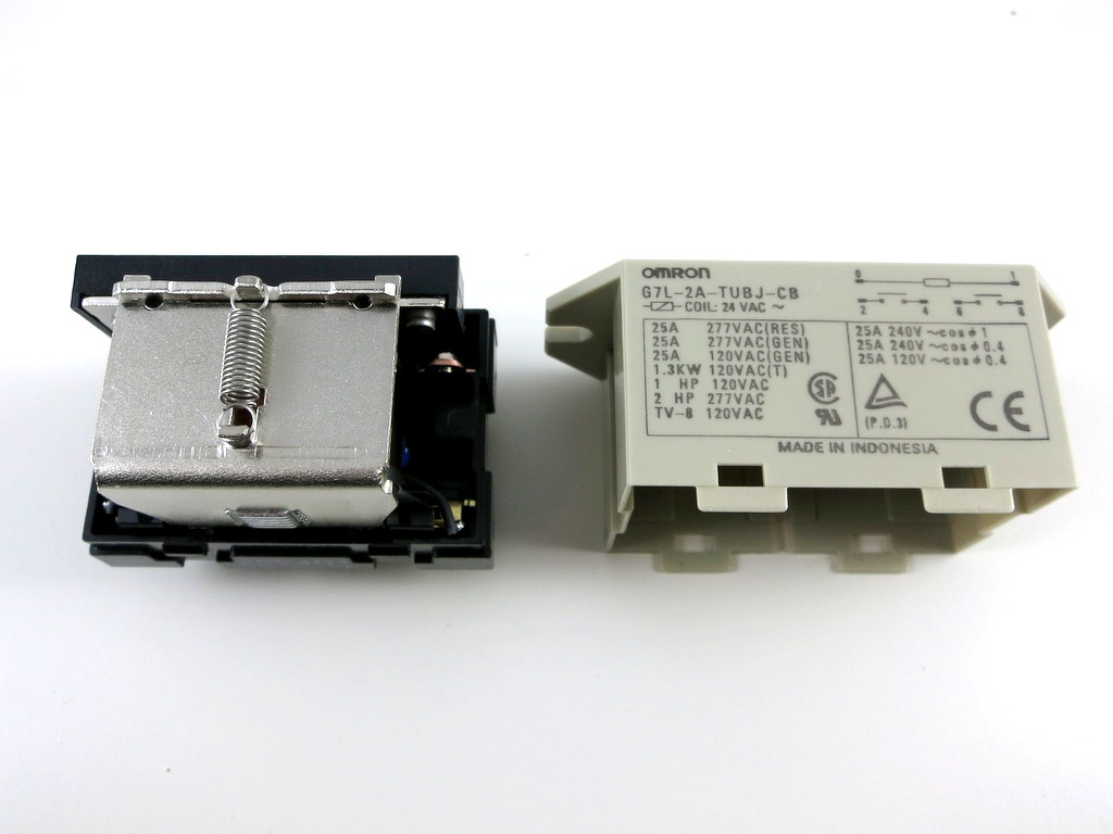
1. Omron G7L-2A-TUB-J-CB-AC24: this is available on Amazon. This is actually commonly used in sprinkler pump start relays — if you have a pump start relay, you can open it up and check if it has a 24V AC relay in side. This particular one has a contact rating of 25A @ 220VAC, which is sufficient for most applications. You can also find similar ones with different specifications: if you search for ‘Omron G7L-‘ you will find many choices, look for the ones ending with AC24, which are the 24V AC versions.
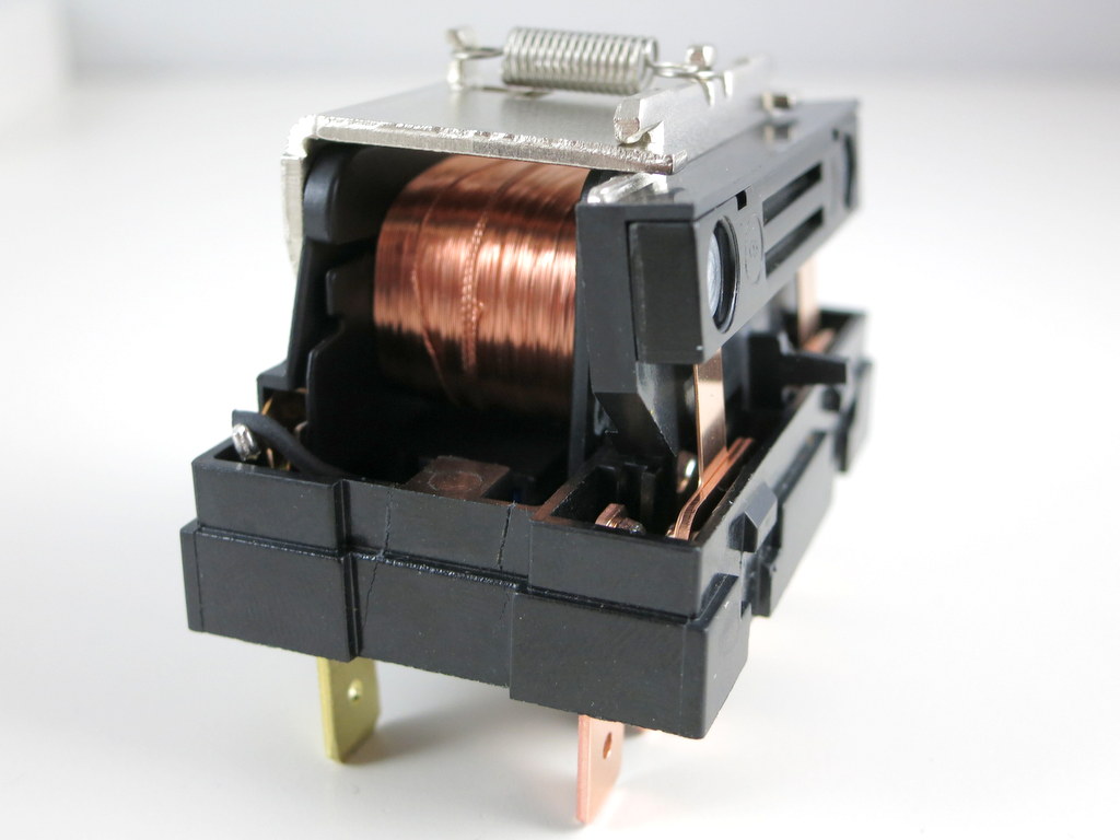
I am quite curious how such 24V AC relays work. It probably is constructed somewhat differently from a DC relay. So I ventured to open it up. As you can see in the picture on the right above, it has a big coil, a contact piece connected via a spring. When voltage is applied on the coil, the contact piece gets attracted and therefore connecting two contact pins together. That’s how a basic relay works.
Something strange I noticed is that when I try to measure the resistance on the coil, it gives me a very large value — several mega-ohms. The coil resistance can’t be that large. There is probably additional circuitry inside the relay. I then measured the forward voltage drop on the coil, at either polarity it gives about 1.25V drop, which strongly indicates there is a bridge (i.e. full-wave) rectifier inside. This makes sense, because a bridge rectifier is a standard way to convert AC to DC. So the additional ‘construction’ inside the AC relay (compared to DC) is probably the rectifier.
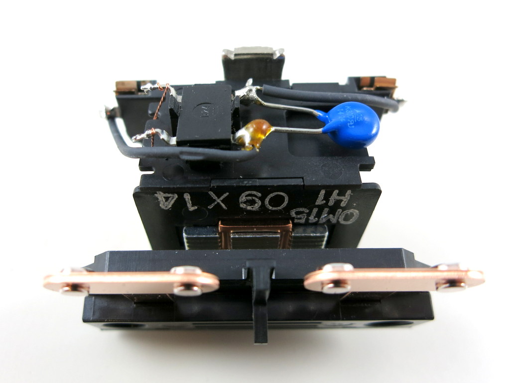
To verify it, I had to open it up even further, which involves cutting some pieces of the plastic. Eventually I was able to open it up completely. Check the bottom section of the relay:
Yup, there is a bridge rectifier and a MOV. Previously I was measuring the resistance through the bridge rectifier, which explained why the value I got was incorrect. Now I can measure the real resistance of the coil, which turns out to be about 294 ohm. That’s about right — under 24V AC, it will draw an average of about 80 mA AC current, which matches the specification.
So in case you are looking for a 24V AC relay to work with OpenSprinkler in order to switch high-voltage devices, this is an inexpensive (<$10) choice and is easy to find.
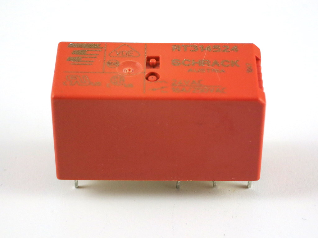
2. Schrack RT314524: This is a very small 24V AC relay that you can buy from Mouser or Digikey. It has a contact rating of 16A @ 250VAC, which is also plenty for common applications.
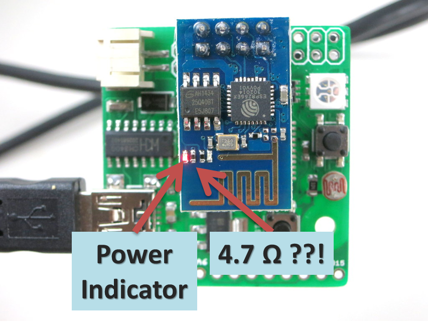
While playing with my ESPToy today, I discovered a rather bizarre issue. The symptom is that some ESP8266 (the ESP-01 version) modules became very hot to touch. In fact, a couple of them started smoking, and the red indicator LED started burning away! Shocking. What’s even more shocking is that these modules continue to function, as if the chip isn’t bothered by the magic smoke at all…
Not all of them have this mysterious problem. So what the heck is going on here? After some digging, I found that on the problematic ones, the tiny resistor next to the red power LED measures only 4.7 ohm?! This can’t be right. This resistor is a clearly a current limiting resistor for the LED — the LED and the resistor are connected in series between VCC and GND. A 4.7 ohm resistor means the current flowing through the LED would be somewhere around (3.3V – 2.1V) / 4.7 ohm = 255 mA! (2.1V is the typical forward drop voltage of red LED). No wonder why the LED (or resistor, or both) is smoking! Phew, that really scared me. To double check, I also measured this resistor on the good ones — they all measure 4.7 kilo-ohm. That’s about right. So clearly the manufacturer has made a mistake and this is really unfortunate. I’ve shot a video of the smoking ESP8266. See below.
Anyway, because some of these defective modules are shipped with the ESPToy, if you’ve bought ESPToy the past few days, you may end up getting some of these units. I sincerely apologize for this. It’s not anything I’ve anticipated. There are several options to solve the issue:
Option 1: let it burn (~~~). Once the LED is burned out and the magic smoke is gone, it will become open circuit and the problem is gone!
Option 2: if it’s scary to look at the magic smoke, or if the LED refuses to burn out, you can use a hot air gun or a soldering iron to remove either the red LED or the resistor next to it, or both.
Option 3: if neither option is ideal, send an email to [email protected] and we can arrange to send you replacements.
Well, this is just one of those headaches to deal with when buying goods from China. To be fair, we buy only from reputable sellers, even so, issues can happen, but we do gain more experience each time a lesson is learned 🙂
When I first had the idea to design OpenSprinkler Pi (OSPi), a secret motivation was that one day I figured out how to fit Raspberry Pi into the existing OpenSprinkler enclosure. Yes, it sounds silly, and you can laugh at it; but if you understand how much it costs to make an injection molded enclosure, and how difficult it is to predict the market and demand, you will see why I wasn’t quite ready to invest on a whole new enclosure for OSPi.
The experience last year has proven that OSPi is quite popular. I really enjoyed seeing the amount of community development on it, primarily due to the low cost of RPi and the flexibility in programming the RPi. We’ve also seen continued evolution of RPi, from the early A and B models to B+ and more recently A+. On the plus side, it’s exciting to see that RPi continues to become smaller and cheaper. The A+ version is now 25% smaller and you can get one for just $20. On the other hand, I am sure the different versions created some challenges in re-designing products powered by RPi. Because each version has different peripheral elements, size, screw hole locations, it’s quite difficult to design one board that fits all versions.
So in a way, I felt lucky that I wasn’t too hasty to invest on a dedicated enclosure for OSPi, because whatever I would have designed would probably not fit A+ in the end. But the lack of a dedicated enclosure has always been the major confusion about OSPi: from time to time I receive questions about why the cutouts on the enclosure do not match RPi, and then I have to explain. It’s not ideal.
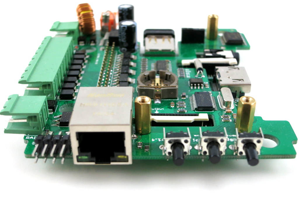
Here comes the good news: with RPi A+, it looks like I may be able to ‘close the gap’ finally — that the injection-molded OpenSprinkler enclosure will finally fit OSPi, without confusing mis-alignment of the cutouts, and with buttons and LCD, just like the microcontroller-based OpenSprinkler!
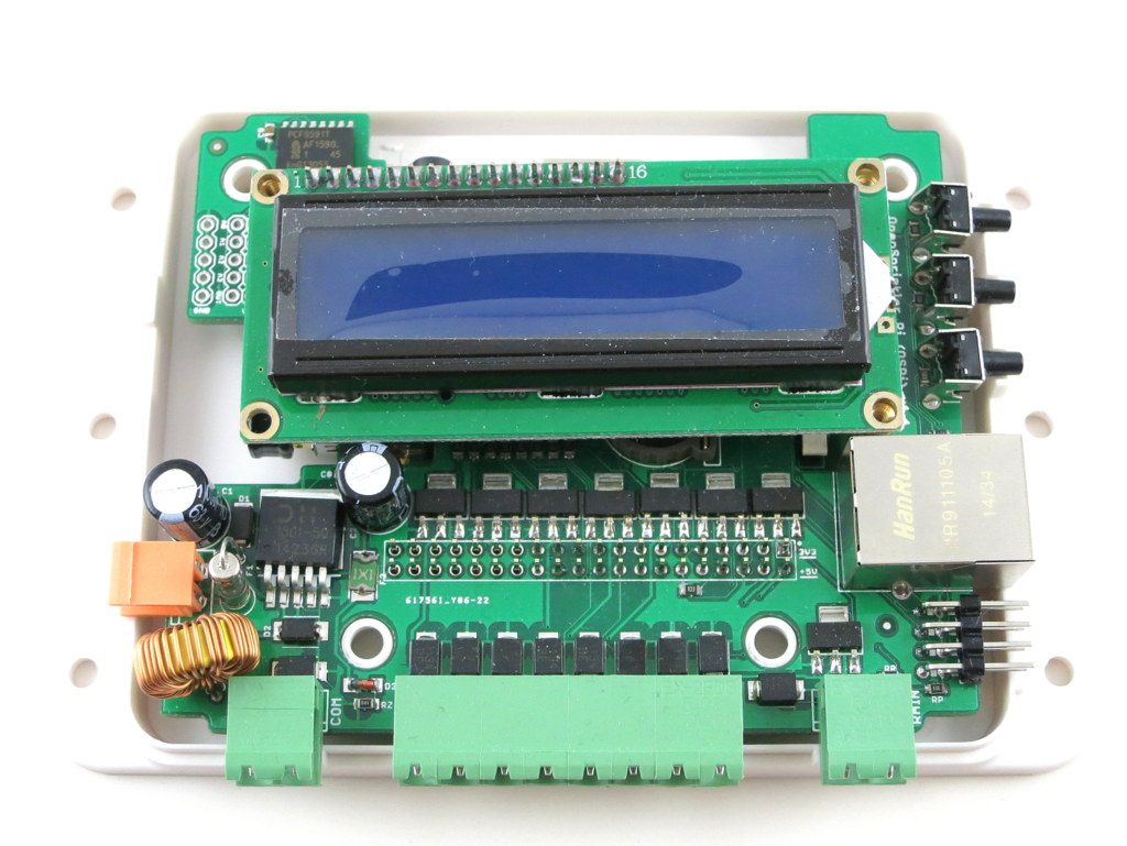
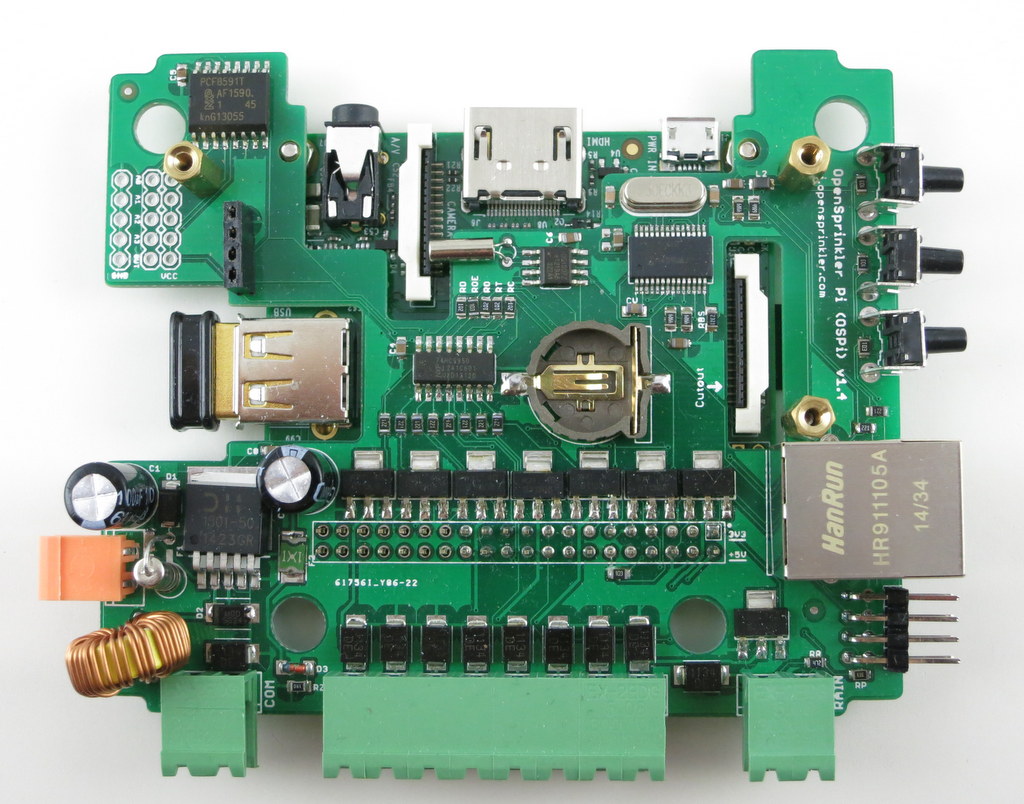
Here are some pictures to show you the proof-of-concept:
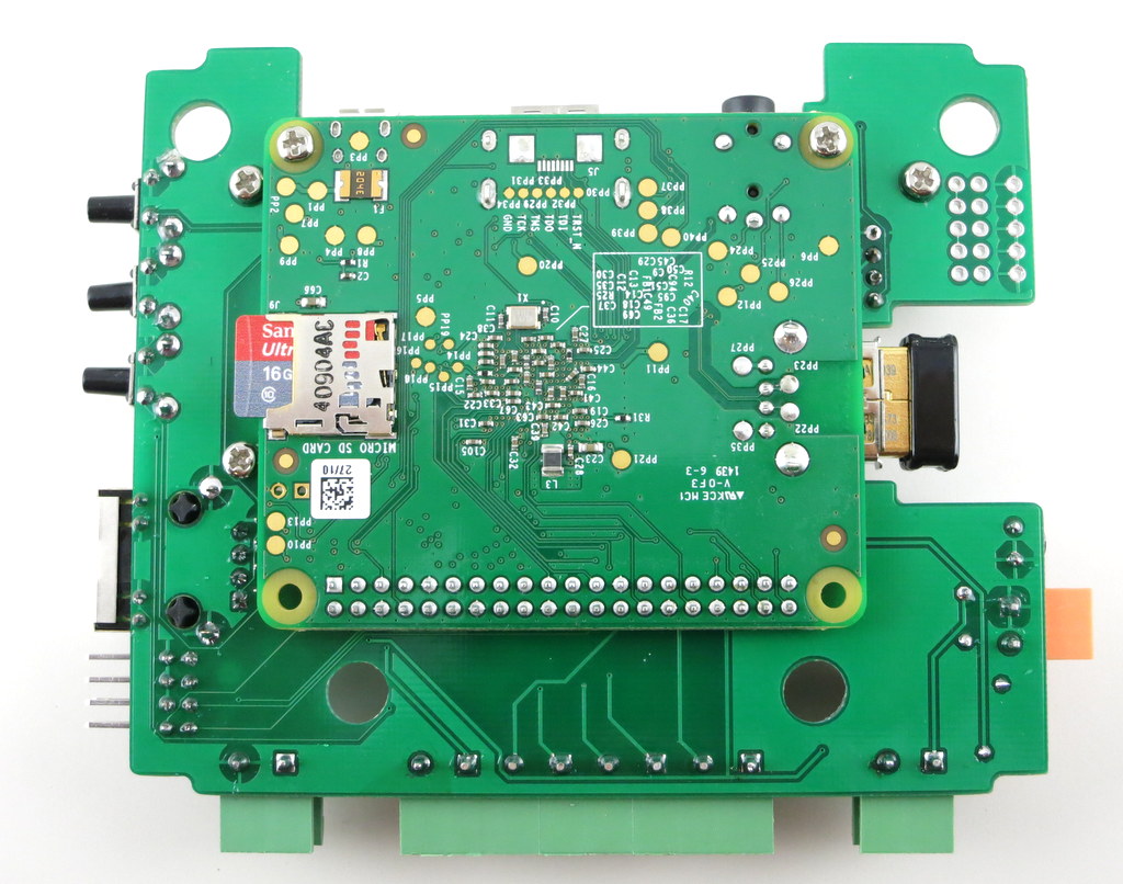
Mounting RPi. The most dramatic change is that RPi A+ will be mounted at the back of the OSPi circuit board. This is necessary to make space for the LCD (explained below). This may look surprising, but because A+ is quite flat, there is sufficient space at the back of OSPI to fit it, except HDMI, USB, and other peripheral connectors, which I’ve made cutouts for.
There is no secret that I’ve always enjoyed solving the ‘how to fit RPi into the OpenSprinkler case’ problem. It’s like a geometry puzzle for me. Often constraints push me to think of new solutions. So bear with the nerdy side of me 🙂
LCD. Next, for the LCD I am using I2C LCD — it’s the standard 1602 LCD with a I2C module at the back. This turns out to be very important, because I2C LCD needs only 4 pins in total (VCC, GND, SDA, SCL), significantly reducing the pin requirement and saving space. You can buy these with pre-soldered I2C modules, at very small added cost.
Buttons. There is also space to fit 3 push-buttons on the right-hand side of the circuit board. The physical buttons can be quite useful for triggering events or performing manual sprinkler control.
Ethernet. Lastly, I don’t want to waste the cutout for Ethernet jack, so I even added a ENC28J60 Ethernet controller. This is a useful add-on for RPi A+, which doesn’t come with an Ethernet jack itself. It took me quite while to figure out how to re-compile the RPi kernel to support this Ethernet controller. Don’t expect it to be very fast, but it comes handy if you really need wired Ethernet connection. Most people will still prefer the WiFi dongle.
One of the biggest drawback of this design is that RPi A+ will now be permanently soldered onto OSPi, because there is simply no space in height to put pin headers. This is not ideal but I can’t think of a better choice. The other potential issue is the heat dissipation of RPi — although there is some space between RPi, OSPi, and the enclosure bottom, it can become an issue during hot summer days. There is some space on the board to make vent holes, so I will see what I can do.
To summarize, this is a proof-of-concept design for OSPi A+ — it will finally make the injection-molded enclosure work perfectly for OSPi. Because this is a very early prototype, don’t expect it to be available anytime soon, although I do hope to make it ready by summer time this year.
Feedback, comments, and suggestions are welcome. Thanks!
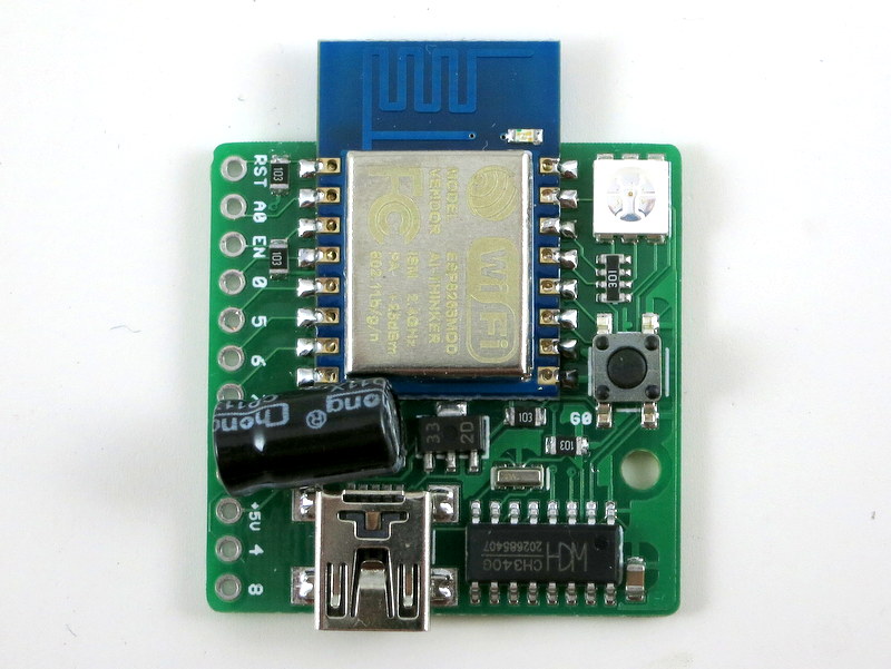
ESP8266 — a very low-cost and flexible Serial-to-WiFi module that has gained a lot of popularity recently. It allows any microcontroller to have WiFi capability by simply using serial communication. In a previous blog post, I demonstrated how to use ESP8266 combined with an Arduino to set up a very simple web server. This time I built a standalone gadget for prototyping called the ESP8266 Toy (or ESPToy for short). There is also a more serious web server demo in the end that shows how to serve HTML files from a SD card, and using JSON and AJAX to implement prettier web design.
You should also know that there has been a lot of on-going development for this module. For example, there is a Lua-based firmware for ESP8266, which is quite amazing. Also check out the community forum here.
ESP-12 SMD WiFi module, pre-flashed with Lua firmware and a startup demo script.
3.3V 250mA linear regulator.
Programming using the on-board mini-USB port.
One color (RGB) LED, one pushbutton (used as a general-purpose pushbutton as well as for re-flashing firmware)
Additional pin headers for connecting external components and/or breadboard experiments.
Original ESPToy v1.0/1.1 (retired)
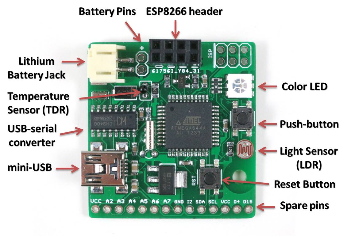
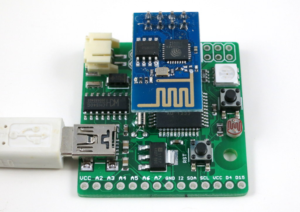
ATmega644 @ 3.3V, 16MHz, with CH340G USB-serial converter and Arduino bootloader.
3.3V 500mA linear regulator.
Programming in Arduino using the on-board mini-USB port.
One color (RGB) LED, one pushbutton, one reset button. (New on version 1.1: one additional button on ESP8266’s GPIO0 pin, useful for firmware upgrade)
One light sensor (LDR), one temperature sensor (TDR).
One 2×4 pin header to fit ESP8266.
Additional pin headers for connecting external components and/or breadboard experiments.
In essence, the ESPToy 1.0/1.1 is a 16MHz Arduino with some handy built-in components for easy prototyping with the ESP8266 WiFi module. Once programmed, the whole assembly can run on battery. There is also a power MOSFET on board to programmably control the power supplied to ESP. This allows you to cut off power to save battery life.
The reason I picked ATmega644 (instead of ATmega328) is that 644 has two hardware Serial interfaces. I am using one for the bootloader and USB communication, the other dedicated for WiFi. This is quite handy and allows you to use the fast baud rates. Also, 644 has twice as much memory as 328, so it’s suitable for building more complex projects.
Demos
As shown in the video above, I’ve written a few examples to demonstrate the basic features of the ESPToy:
To upload the demo Lua scripts to ESPToy 1.2, download and run the ESPlorer software. The Serial port baud rate is 9600 (default). You can open a demo script, click on ‘Save to ESP’ to save the script as a file to ESP’s internal flash memory space. The script will run right away after uploading. You can also click on ‘doFile’ to re-run the script.
Start-up Demo: every ESPToy 1.2 is pre-flashed with a start-up demo. Plug in a mini-USB cable, the blue LED will blink and the WiFi module will start in access point mode, creating a WiFi network with SSID ESPToy-xx. The password is opendoor. Connect to this WiFi network, open a browser, and type in http://192.168.4.1. Use the sliders to change the LED color, and click on ‘Refresh Value’ to read button status and analog pin value.
Hello ESPToy!: shows the Serial print function.
Blink LED: shows digital pin write, and delay functions.
Button Interrupt: shows how to set up interrupt on a digital pin.
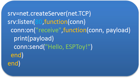
Hello ESPToy Server: shows a simple HTTP web server.
Original ESPToy v1.0/1.1 (retired)
SearchBaud: this comes handy if you forgot the correct baud rate of your ESP8266. It loops through the common baud rates, sends an empty AT command, the detects the correct baud rate by checking the result.
SerialCommand: this demo allows you to send AT commands to ESP8266 through a Serial monitor. Use this demo to experiment with all the AT commands available for ESP8266.
ScanNetwork: this demo starts the ESP8266 in AP mode, which creates a local WiFi network (the name is ESPxxxx). Use a smart phone or laptop to log onto this network, then open a browser and type in IP adddress 192.168.4.1. You will see a webpage with a list of detected WiFi networks. Type in the ssid and password of the target network, then click on Connect. The page will redirect in about 10 seconds to show the client IP address of the module on the target network. This is pretty standard approach to get your WiFi-enabled gadget to log on to your target network.
WebServer: this is a simple web server demo. It serves a html webpage and uses JSON and AJAX to periodically display the analog pin values. The first two analog pins correspond to the light and temperature sensors respectively, so these two values will respond to light and temperature changes. There are also three sliders to set the color of the on-board LED. As I said before, the demo can run on battery, so this can be used as a WiFi-enabled color LED light. Thinking about a simplified version of the Philips Hue? Yup, this is a poor man’s version of that 🙂
WebServer_SD: same as above, except this requires an external SD card slot, so that it can serve bigger and multiple html pages from files stored on the SD card.
Preparation
The ESPToy’s source code is available on Github. Check the README file therein to get started.
Serial Port and Driver:
ESPToy uses a CH340G USB-to-Serial converter. For:
Windows 7, 8, 8.1 and Linux: no driver installation is needed.
On Windows, the Serial Port name is COM? where ? is a number assigned to the USB-serial chip. On Linux, the Serial Port name is /dev/ttyUSB? where ? is a number. On Mac, the Serial Port name is tty.wchxxx.
Programming ESPToy 1.0/1.1 (retired)
Programming the ESPToy can be done through the Arduino IDE (tested with Arduino version 1.0.6). Because ATmega644 is not a board that appears in the stock Arduino, you will need to copy the atmega644 subfolder (from the hardware folder) to the corresponding hardware folder in your Arduino’s installation directory; same with the ESPToy subfolder (from the libraries folder).
Next, launch the Arduino IDE, select Tools->Board->ESPToy, and the correct Serial port from Tools->Serial Port (see below), then select a program from File->Examples->ESPToy, and finally click on Upload
Power Options:
ESPToy can be powered by USB or an external battery. There is a battery jack that fits a standard 3.7V lithium battery. In addition, there are two battery pins (next to the battery jack) — you can solder wires to connect a 3V AA/AAA battery pack. Note that the external AA/AAA battery should not exceed 3.6V (because it’s not regulated).
Flashing a New Firmware to ESP8266
Programming ESPtoy with Arduino: I strongly recommend you to learn to use Arduino to program ESPtoy, due to its flexibility and memory efficiency. While Lua firmware is easy for beginners, to write advanced programs, it’s much easer to use Arduino. Check the resources in this forum post.
On ESPToy 1.2 and 1.1: there is a pushbutton button (on version 1.1 it’s at the upper-left corner) — it’s connected to ESP8266’s hardware GPIO0 pin. If this button is pressed when powering up ESPToy, the ESP8266 will enter bootloading mode waiting for a new firmware. I recommend using the esptool python program to upload firmware, which is very easy to use. Specifically, in command line, run ./esptool.py write_flash 0x00000 xxxx.bin where xxxx.bin is the firmware name.
On ESPToy 1.1, use the SerialCommand sketch to prepare ESPToy as a serial relay.
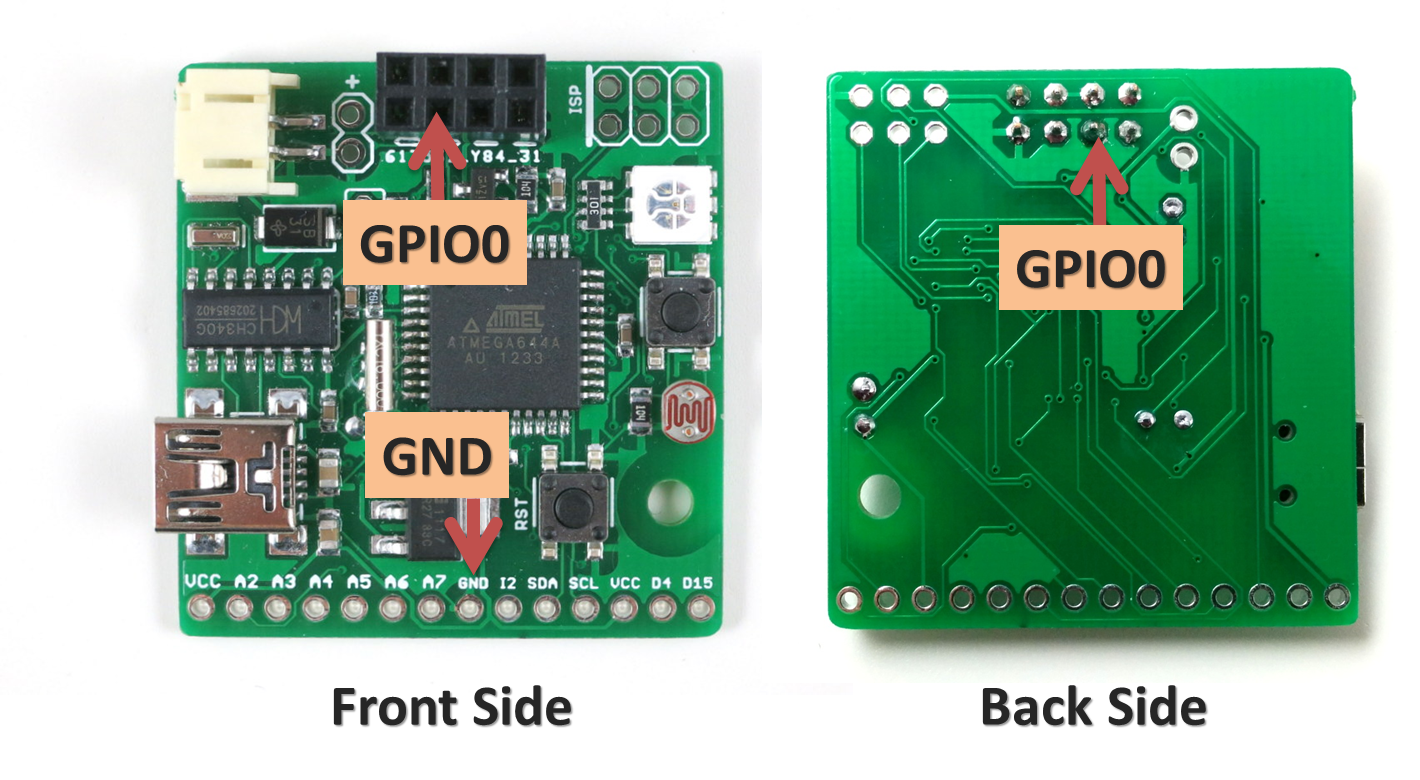
For ESPToy 1.0 (retired): to let ESP8266 enter bootloader, you need to solder a wire from ESP8266’s GPIO0 pin to ground. Specifically, if GPIO0 is pulled to ground, upon power-up ESP8266 will enter bootloader mode waiting for a new firmware from the Serial interface. In contrast, if GPIO0 is pulled up (to VCC), ESP8266 will boot into normal operation mode.
The picture below shows where the GPIO0 pin and a ground pin (any ground pin on the board should work). The wire should be soldered at the back of the circuit board. You can also connect a switch in series on the wire to easily switch between bootloader mode and normal mode.
Once this is done, you can flash the SerialCommand sketch to ESPToy, which will make it serve as a Serial relay. I recommend using the esptool python program to upload firmware, which is very easy to use. Specifically, in command line, run ./esptool.py write_flash 0x00000 xxxx.bin where xxxx.bin is the firmware name.