OpenSprinkler will improve your lawn, garden, or farm irrigation. Create custom programs and use our automatic weather-driven algorithms. Access and control your sprinklers from anywhere.
An EagleCAD Script for Creating Laser-Cut Project Enclosures
When designing electronic circuits, often it’s necessary to have a proper enclosure for the project, to protect the circuit board and components, and for aesthetic reasons. There are several options to choose from. For example, if this is a one-off project, you can pick an off-the-shelf enclosure, make custom cutouts to fit the PCB and its buttons, connectors etc. But you will be limited by the enclosures available on the market, and you have to design the PCB size and screw hole locations according to the enclosure, so it’s not very flexible. You can also use 3D printing to make a custom case that fits the PCB nicely, but 3D printing is generally slow, and cheap 3D printers have poor precision. If you are making a commercial product and need volume production, you can order an injection mold, and the injection-molded enclosure fits the circuit perfectly. But you have to spend costs thousands or tens of thousands of dollars to order the mold, and this upfront cost is too much for small-scale projects.
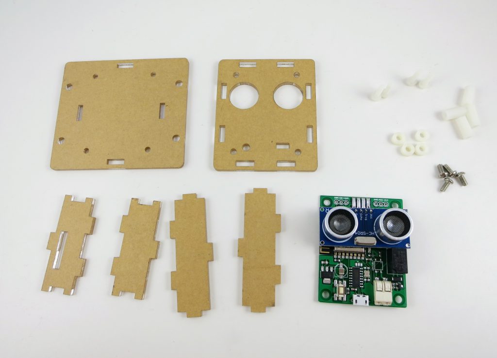
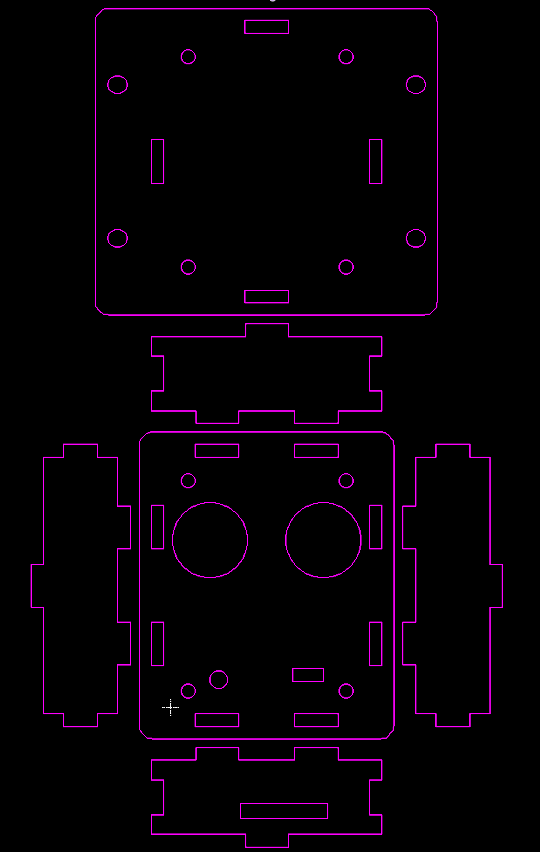
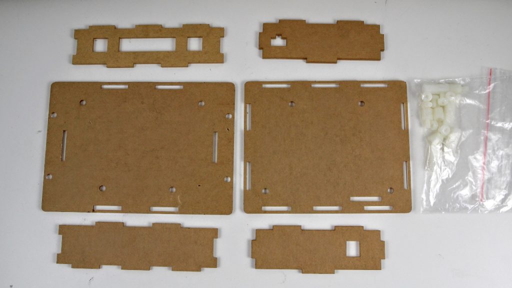
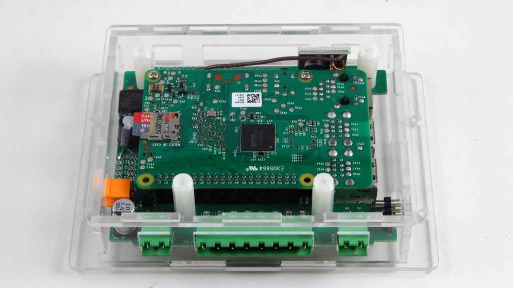
Since last year I’ve been experimenting a lot with laser-cut acrylic enclosures. Compared to the other options, laser-cut enclosures are very easy to customize for the particular PCBs I have designed; they are relatively cheap and fast to make, you can add text engravings to them, and there is no upfront cost. So I have been using laser-cut enclosures a lot for a variety of electronics projects. Generally speaking, the enclosure consists of six pieces of laser-cut acrylic panels, with teeth and holes on the side to lock them together and form a box. You can use plastic or copper screws and pillars to secure the PCB inside the box. As a side benefit of this type of enclosure — if you happen to make a mistake on one panel (which I did a few times), you can just re-order that particular panel so it’s very easy to re-design and correct the mistake.
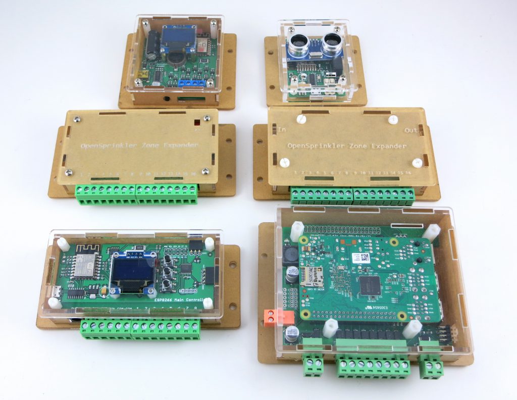
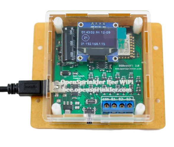
When I started, I found some tutorials and design tools online, to help create the six panels. But they are not really convenient or easy to work with. Because I routinely use EagleCAD to create my circuit boards, it would be really nice to have a enclosure design tool inside EagleCAD, so that I can compare the enclosure with the PCB precisely, making sure that all the cutouts are in the correct locations and have correct sizes. So a little while back, I wrote an EagleCAD script to help me create laser-cut enclosure panels, and used it to create a variety of project enclosures, as shown in the picture below.
Below I will briefly walk through the details of the script, what the various parameters mean, and I made a video to demonstrate how to use this script. To begin with:
Video Tutorial
Explanation of Parameters
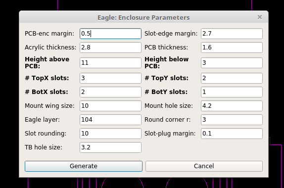
The way this script works is that it follows the dimensions of your PCB outline to create the six panels. It assumes the PCB is rectangular shaped, but if needed you can modify it to support non-rectangular shaped PCBs. There are a number of parameters you need to set, which I will briefly walk through below. Most of them are best explained by the annotated images below. All parameters of lengths are of unit millimeter (mm).
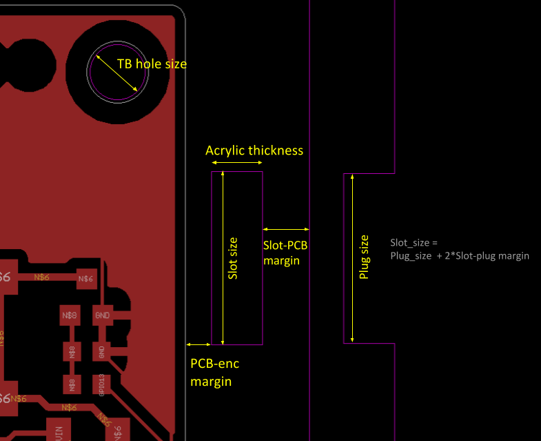
- PCB-enc margin: the margin from PCB border to enclosure interior border.
- Slot-edge margin: the margin from the slot boundary to enclosure edge.
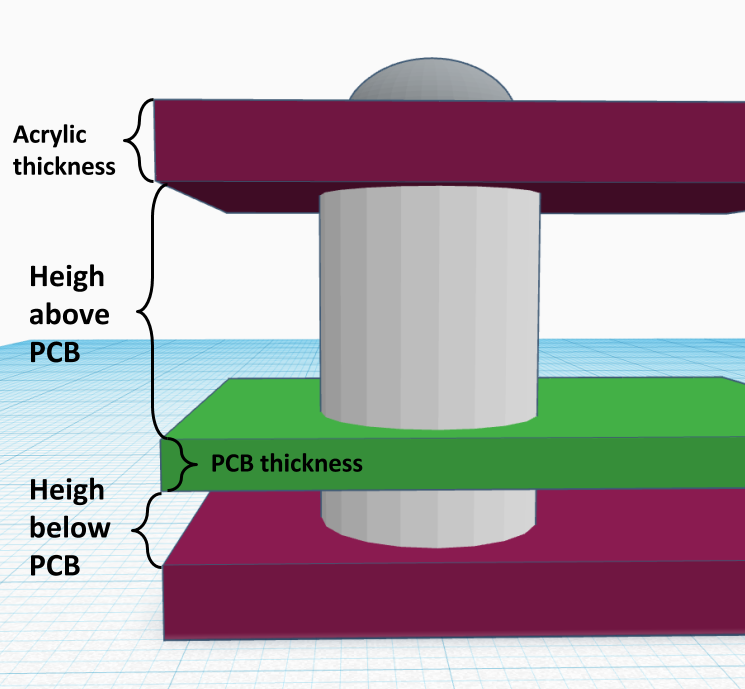
- Acrylic thickness: the common acrylic material I’ve used are either 2mm thick or 3mm thick. You may have to adjust this slightly according to your supplier’s acrylic material thickness. You may want to make this slightly larger (like 2.1mm and 3.1mm respectively) to account for error and variations in the actual material.
- PCB thickness: standard PCB thickness is 1.6mm, but there are other choices too, like 1mm, 1.2mm, 2.0mm etc.
- Height above/below PCB: this defines how much space there is above and below the PCB (NOT including acrylic). The ‘above’ height depends on the tallest component on your PCB. The ones I commonly use are 11mm and 13mm. The ‘below’ height is typically 3mm, to provide spacing underneath the PCB for through-hole components.
- Top/Bot X/Y slots: define the number of slots on the top/bottom panel and in the x/y directions. The number of slots depend on the length in x or y: longer edges probably need more slots. Also I generally make the number of slots on the top and bottom panels different, to make it easy to identify the orientation of the side panels.
- Slot rounding: this will round the slot size to the nearest (ceiling) multiple of the slot rounding number. The slot size is automatically computed based on the number of slots. If you want the slot size to be rounded to the nearest multiple of 10, for example, you can set slot rounding to 10.
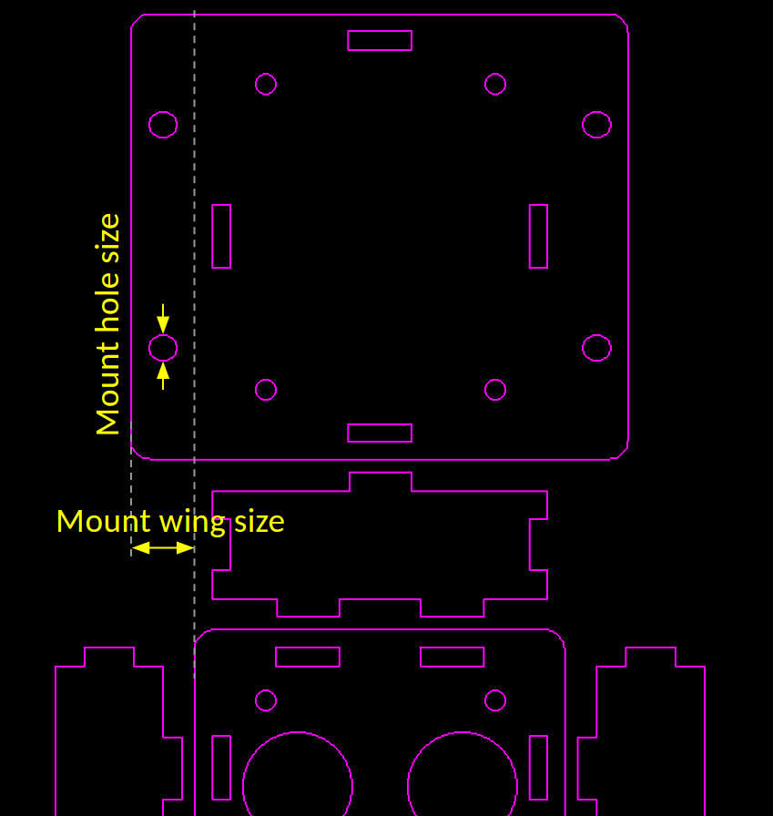
- Mount wing/hole size: if you need the back panel to be wall-mountable (which is generally the case for my boards),
you can define the width of the wing and mount hole size (diameter). - Round corner r: radius of the rounded corners.
- Slot-plug margin: this will shrink the plug size slightly to make it easy to insert into the slot. The default is 0.1mm but I suspect leaving it 0 is fine (because laser cut holes generally have negative error, meaning they are larger than design).
- TB hole size: top-bottom hole size. This is set according to the size of screws/pillars you need. For example, if you plan to use M3 screws, set this to be slightly larger than 3.0; if you plan to use M4 screws, make it slightly larger than 4.0 and so on.
- Eagle layer: defines which Eagle layer it uses to draw the enclosure. By default it uses layer 104.
Running the Script: upon running the script, it will hide all layers except the Acrylic layer (104 by default). This allows you to see the overall enclosure design. You can go back and un-hide the other layers. If you re-run the script, it will remove the existing content on the Acrylic layer, and re-create the outlines. So be careful re-running the script — if there is anything you want to preserve (such as custom cutouts as explained below), you want to put them in a different layers so that they don’t get wiped out.
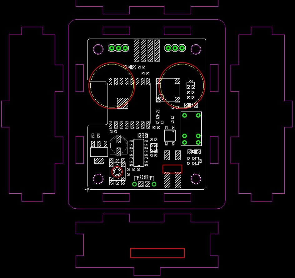
Annotated figures are more intuitive for explaining the parameters:
Creating Custom Cutouts and Text Engravings
The script doesn’t automatically create cutouts for connectors, and that part you have to do it yourself. Still, having the enclosure outline embedded with the PCB design makes it easy to align the cutouts with the connectors. As shown in the last image above: the custom cutouts (colored in red) are embedded in the PCB design, so you can precisely align each cutout with its designated connector. I generally create the custom cutouts in a different layer, so that in case the Acrylic layer gets wiped out, the cutout layer is still preserved. You can also add text engravings — where I order acrylic pieces, they can add laser engravings for only a small amount of additional cost. So if I need any labels for the connectors, I can easily add them to the custom cutout layer and get them ordered as engravings.
Order Laser-cut Acrylic Pieces
Once the design is finalized, I place an order from a vendor on Taobao.com — the Chinese equivalent of eBay. To prepare the design for ordering, I export the Acrylic layer and Custom Cutout layer together into a DXF file in EagleCAD, then convert it to Adobe Illustrator (.ai) file, and send it to the vendor. I then specify the acrylic thickness, color (the most common is transparent, but there are a variety of other colors to choose from). Make sure the scale of the design is appropriate — Chinese vendors work with millimeter (Americans should too!), so make sure the design is scaled to the correct millimeter scale, which you can do easily in Illustrator.
Assemble the Enclosure
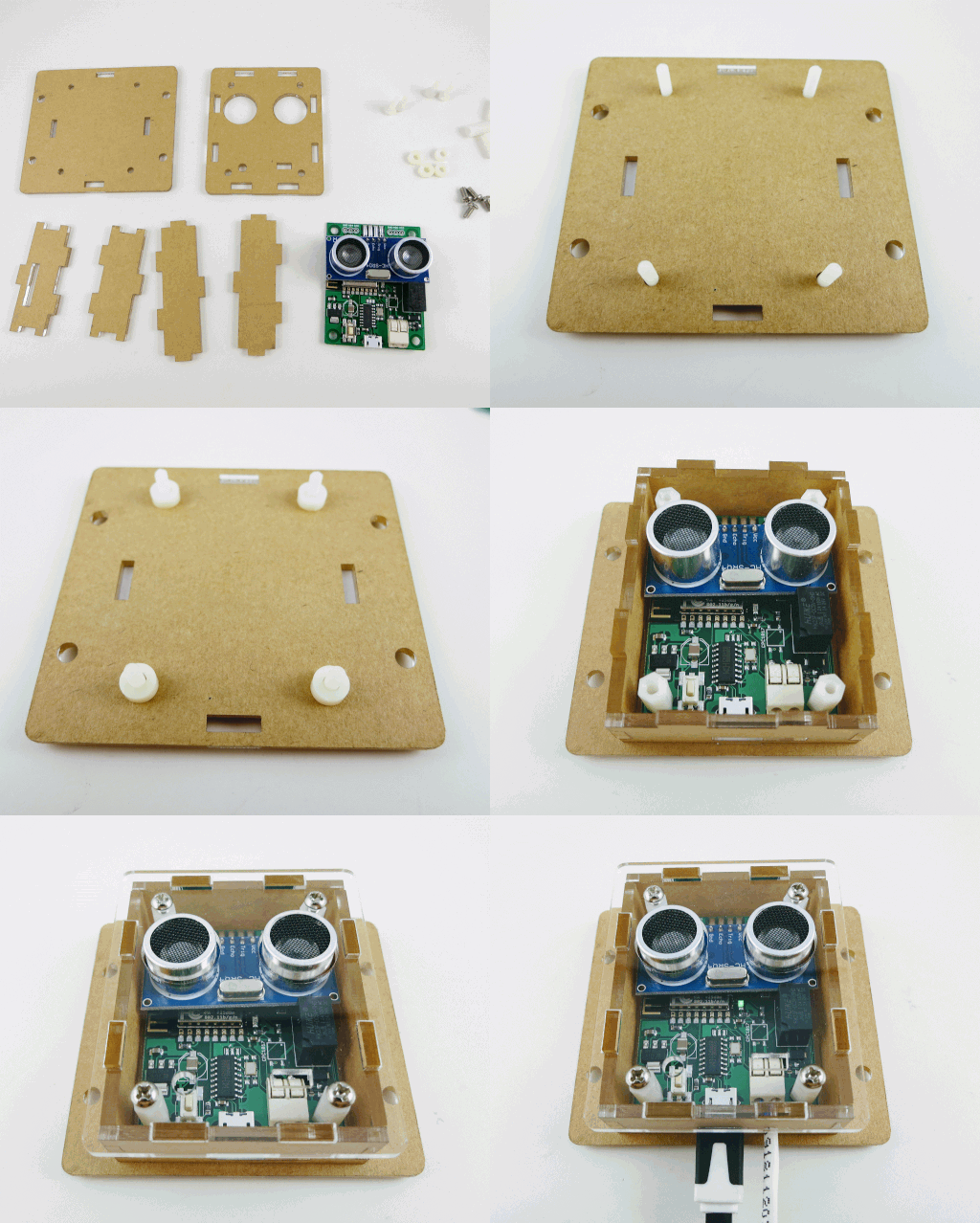
Assembling the enclosure is fairly straightforward: it involves a set of screws on the top panel and bottom panel, and separation pillars below the PCB and above the PCB. I generally like plastic screws and pillars as they are much lighter than iron or copper screws and pillars. The acrylic pieces come with a brown protective sticky paper cover. You can peel the sticky paper cover. If the acrylic material is transparent, you can see through the enclosure to the circuit board, which looks pretty cool. I generally only peel the top panel and keep the protective cover on the other panels, because peeling a lot of paper is tedious, and the brown paper cover gives a wooden appearance, which is not bad. So I keep them as much as possible. To peel the cover, it’s best to use another acrylic piece, or a stiff card of some sort to lift the cover from one corner, then carefully peel and remove the entire cover. Don’t use your nail as it can easily damage your nail. Acrylic is reasonably scratch-resistant, so using another acrylic to help peel it is totally safe.
The GIF below shows the assembly process:
Limitations and Todo for the Future
Perhaps the biggest limitation of laser-cut enclosure is the assembly time — putting all those screws and pillars together cost time and labor. But given that there is no upfront cost, it’s pretty suitable for small-scale projects, or serving as a temporary enclosure until you have a more permanent solution like an injection mold. In addition, for DIY-style projects, you can give the enclosure pieces to the customers and let them assemble the enclosure. It’s actually quite fun, kind of like the philosophy of Ikea furniture — its value is not only in the low cost but getting yourself involved in assembling the product provides a more engaging experience.
There are a couple of improvements I want to make to the script and I will try to work them out in the future. One is the ability to create a local file to store the parameters. At the moment if you want to re-design the enclosure for the same circuit, you have to manually remember what parameters you have used before — the script doesn’t remember the previous parameters because every time you run it, it will load the default parameters. It would be nice for it to store previous parameters for a particular circuit board to a local file, making it easy to modify in the future. Another improvement is providing visual aid to indicate where the PCB is located on the side panels, to make it easier to design cutouts for connectors etc. Right now to create cutouts I still have to do a lot of hand calculations, which can be automated in the future.
That’s it. Feel free to try it out and let me know what you think. If you make modifications to the script and improve its features, please be generous to share your contributions!


