SquareWear 2.0 used at Mount Holyoke College’s iDesign Studio Class

This past week has been a hectic week. Since SquareWear 2.0 got posted on Hack A Day, things have gone quite wild: we’ve got hundreds of orders, and the SquareWear YouTube video accumulated 80,000 views in just two days. By the end of last week, it has exceeded 100,000 views and has officially become the most popular video at the my YouTube channel.

Among the many emails I received, one common question is what can one use SquareWear for other than the examples demonstrated in the video. Well, at heart SquareWear 2.0 is really just a small Arduino with lots of built-in components (notably built-in rechargeable battery and USB port). The large pin pads make it suitable for wearable electronics projects, and the small size makes it suitable for general-purpose microcontroller projects. For example, I’ve used SquareWear to build a reflow oven controller, a OpenSprinkler Pi tester, a USB-based remote for RF power sockets. It’s really versatile.

If you are looking to make some artistic projects, you will be glad to hear this: SquareWear 2.0 was used at the Mount Holyoke College for their iDesign Studio Class. This class was offered by my friend Audrey Lee last semester, and they’ve just concluded the class last month with a fantastic final presentation. I am going to highlight some of the best projects below. For additional information, check the link above — each project has a website with detailed write-up. I am sure they will inspire you to come up with your own fantastic project idea.

One of my favorite is the Accelexpression project by Madeline Ketley. She combined a SquareWear with a gyro sensor and NeoPixel LED strip to make a smart skirt for dancers. The LED strip displays different colors depending on the standing position of the dancer. It is not only artistic and visually beautiful, but it’s a very useful tool for training dancers: from the color of the LEDs you can easily tell if the dancer is standing straight, or if two dancers are synchronized in their moves. It’s a brilliant idea and I was completely impressed. Here are some rather blurry pictures. I wish I had taken high-quality pictures or even better a video!

IMG_3796IMG_3797IMG_3823

Another favorite of mine is Meaghan Sullivan’s Reading Hardwired. Meaghan made a hand-drawn picture book featuring a timid and cute cameleon. She then combined a SquareWear, copper sheets, some neopixels, and photo-resistors to make the picture book change colors as you turn the pages. It’s so artistic, vivid, and truly brilliant!
IMG_3812IMG_3813

Neopixels seems to be a big hit among students. Alexis Andrus used strips of Neopixels to make a beatuful iDesign Jacket; Ione Brogna also used Neopixel strips to make iTech Accessories, such as these stylish shoulder straps belts. Ione also added a sound sensor to SquareWear and made her iTech accessories respond to music and beats.

IMG_3780IMG_3783IMG_3786IMG_3822

Next up, with Julia Rycyna’s La Coeur du Dragon project, we enter the fantasy land of dragons. She first made a plush dragon with flapping wings using a SquareWear and some muscle wires. Thanks to the build-in MOSFETs on SquareWear, no external muscle wire drivers were needed. Then she added a ultrasonic distance sensor and a LED heart to the dragon, so that the heart blinks faster as you approach the dragon. Quick, hold it tight, how can you bear with putting such a lovely dragon down!

IMG_3807IMG_38202534840_orig

Safae Lahgazi Alaoui presented an amazingly artistic project called the Interactive Mirror. The mirror is decorated with LEDs and responds to sound, touch, and motion. Check the images below and appreciate the complexity of the mirror.

IMG_3802

Eva Snyder’s musicTouch project is a great educational tool to teach kids about music and tones. It uses conductive ink and touch sensing to let you play music interactively. If you are interested, be sure to check out my previous blog post about how to use SquareWear to create a touch-based digital piano without any additional hardware.

IMG_3808

Thinking of some other creative uses of SquareWear? Saadia Gabriel made a solar charging jacket called The Turtle? It makes use of SquareWear to charge a lithium battery, which is then bumped to 5V using a boost converter for charging cell phones. Athena Donta and MJ Lee created the Bad Weather Wear project, which combines a SquareWear, LED matrix, and conductivity sensor onto a pair of mittens. When it rains or snows, the LED matrix displays smileys and different patterns to keep you happy in bad weather. Isn’t that sweet?

IMG_3793IMG_3789IMG_3790

If you are inspired by these projects, consider getting a SquareWear 2.0 from our shop. It’s a great little gadget to help explore the creative and artistic side of you!

SquareWear 2.0 Touch Sensing and Digital Piano Demo

Looking for new projects to do with SquareWear 2.0? Here is an idea: combine SquareWear 2.0 with touch sensing to make a digital piano! It works as a standalone project and no additional hardware is required. Take a look at the video first:

How does this work? First, SquareWear 2.0 has a built-in buzzer, so it can already make sound. Next, touch sensing is detected in software. It basically exploits the principle of capacitive sensing: every time you touch an Arduino pin, it slightly alters the capacitance of the pin. This change of capacitance can be detected using a variety of methods. The simplest is to set the pin to digital input mode, and turn on the internal pull-up resistor. This will start charging the capacitor. By detecting the time it takes to charge the capacitor, you can infer the capacitance, and in turn tell if a finger touch has occurred on the pin. That’s it! Because SquareWear maps out available pins to large pin pads, this makes it particularly well-suited for touch sensing.

So I wrote a quick demo as a proof-of-concept. First, I found a function that implements the capacitive sensing from the Arduino playground website. It basically returns a touching sensing value, which can then be compared to a threshold. You may need to adjust the threshold to increase or decrease the sensitivity. The demo scans through all 12 pins available on the SquareWear 2.0 and plays a tone for 125 milliseconds if a pin touch is detected. As a result, the buzzer makes a chiptune type of sound. The code also uses the on-board pushbutton to switch between three octaves: C3, C4, and C5. The LED will blink when a tone is played.

A few notes and quirks:

  • The code works the best if you plug in a USB cable connected to your computer.
  • You can also moisten your figures to help increase the touch sensitivity.
  • If you unplug the USB cable, it generally helps if you use one hand to hold the battery, or the VCC or GND pin. You may need to cover the ISP pins on the back side to avoid touching them. Holding the battery, VCC or GND helps amplify small capacitive changes.
  • The MOSFET pins (D3, D5, D6) do not seem to work well without the USB cable. To be honest, I was surprised that these pins even worked at all, because the pads are not directly connected to the pins (rather, the connection is through a MOSFET). So if you need, you can modify the source code to disable these pins.

The demo code is available in the SquareWear 2.0 software package on Github. The direct download link is below:

I will keep posting new project ideas in the upcoming weeks. SquareWear 2.0 is available for purchase at the Rayshobby Shop. At a price of $22 and with a load of built-in components, it’s a great little gadget to help you learn Arduino programming, and build wearable as well as general-purpose electronic projects. Hope you like this demo and your support is greatly appreciated!

OpenSprinkler v2.1u Semi-Assembled DIY Kit Available Now!

Great news, OpenSprinkler v2.1u semi-assembled DIY kit has now been officially released and available immediately for purchase at the Rayshobby Shop! This version marks a major upgrade from the previous DIY kit v1.42u. With ATmega644 MCU, microSD card slot, and injection-molded enclosure, it not only brings the DIY kit up to speed with the fully assembled v2.0s, but it actually strives to be a little better (hence the migration on the version number) 🙂

In particular, it adds a mini-relay for general purpose switching (similar to the one on OpenSprinkler Beagle), changed the 24VAC terminal to an orange colored one with different pin spacing, and increased MCU frequency from 8MHz to 12Mhz. It also uses a USBasp bootloader built-in on the ATmega644 MCU for firmware flashing (while all previous versions use a separate ATtiny45 chip). The USBasp bootloader significantly improves the firmware upload speed, and is therefore very helpful if you are making frequent changes to the firmware. These changes are all described in the prototype sneakpeak preview post. Finally, the MCU is pre-loaded with the latest firmware 2.0.3 with several new features compared to the previous firmwares.

osdiy_headerIMG_3758

Another notable change is that v2.1u is the first semi-assembled DIY kit which comes with a partially assembled circuit board with through-hole components. I’ve designed it this way to help reduce the amount of soldering you have to do, while still let you enjoy the process of building, assembling, testing, and hacking the circuit. It’s a first-time experiment, so I will keep my fingers crossed.

In any case, if you’ve been waiting for OpenSprinkler DIY kits, go grab one quickly before it’s gone; if you already own an OpenSprinkler or have heard of OpenSprinkler one way or another, I would appreciate if you can help me spread the word. Thanks!

IMG_3762

Modified Arduino DS1307RTC library that also works for MCP7940N

DS1307 is an old and classic real-time clock (RTC) chip that has been used in many electronic circuits. There are also many libraries written for DS1307, notably this Arduino Time library which includes a DS1307RTC class. Given its age and popularity, it’s surprising that the chip is not cheap: even at volume pricing, it usually costs around $2 each. Even a microcontroller like ATtiny45 costs only about about 60 cents. How complicated can an RTC chip be compared to a microcontroller!

Recently I came across Microchip’s MCP7940N, which is less expensive and is pretty much a drop-in replacement of DS1307. At a quantity of 100, it costs 65 cents each, which is about a third of the price of DS1307. To be fair, there are even cheaper options, but those often do not have battery backup support, which would not be desirable.

IMG_3832

Microchip has published a DS1307 to MCP7940N migration document which thoroughly explained the differences between the two. To begin, Microchip recommends adding a few extra elements, such as load capacitors for 32.768kHz crystal, and protection circuitry for the backup battery. If you are not so concerned with this level of reliability, you can leave out these elements and hence it will be truly a drop-in replacement.

Next, there are a few software changes we have to make, mainly three:

  • I2C address: MCP7940N uses address 1101111 while DS1307 uses 1101000.
  • Clock enable: MCP7940N uses active high while DS1307 uses active low.
  • Battery backup: MCP7940N disables it on startup while DS1307 always enables it.

These changes are fairly easy to make. So I modified the DS1307RTC library to accommodate both. The library can automatically detect which RTC chip you have. Using the modified library, you need to first run RTC.detect() to detect whether an RTC chip is installed and which one it is. The detect() function returns 0 if either DS1307 or MCP7940N is detected, and a non-zero value if an error has occurred. The rest is the same as before.

This library can replace the one included in Arduino’s Time library. Note that it also works for DS3231, which is compatible with DS1307 but with a built-in temperature compensated crystal.

That’s all. Next time you need an RTC, perhaps you will consider using MCP7940N as an inexpensive alternative to DS1307 🙂

Introducing SquareWear 2.0 — An Open-Source Wearable Arduino

This is a long delayed post. I am glad I finally finished making a video for it, and it’s time to introduce SquareWear 2.0 — an open-source, wearable Arduino microcontroller board. At heart, SqureWear 2.0 is an Arduino running at 3.3V and 12MHz. It has built-in mini-USB port for uploading programs, charging lithium batteries, and creating a serial communication channel. It comes with a lot of useful built-in components, such as a color LED, a general-purpose push-button, a buzzer (yup, you can make it sing a tune), light sensor, temperature sensor, three MOSFETs (to drive high-current load). Even better, it has a built-in rechargeable lithium coin battery (you heard it right: rechargeable coin battery!), so you can power your project right away without requiring external power supply. Every time you plug in the mini-USB cable, it charges the coin battery automatically. Better still, if you want a beefier battery, you can plug in an external lithium battery through the on-board battery jack. The built-in lithium charger can charge external battery as well. Overall SquareWear 2.0 packs a lot of useful features on a 1.7″ x 1.7″ board. It’s great for wearable electronic projects as well as general-purpose microcontroller projects. Below is a summary of built-in components:

  • ATmega328 running at 3.3V, 12MHz.
  • MCP1700 3.3V / 250mA LOD.
  • MCP73831 lithium charging chip (configured to charge at 35mA).
  • MCP9700 temperature sensor.
  • 10K photo-resistor.
  • Four 2N7002 MOSFETs.
  • 5050 color LED.
  • 8.5mm SMT buzzer.
  • 6mm SMT tactile button.
  • Charging indicator LED.
  • LIR2032 rechargeable lithium coin battery (45mAh capacity).
  • 2.0mm JST connector for external lithium battery.
  • SMT mini-USB port, and power switch.

IMG_2856IMG_2861IMG_2858

squarewear2_annotation

Last year around this time I released SqureWear 1.1, which is based on Microchip’s 18F14K50 microcontroller. It’s pretty neat, but over time I’ve received quite a few requests to develop a similar board based on the Arduino. This inspired me to work on SquareWear 2.0. Many design choices, including components I selected to put on board, were based on feedback and experience at various wearable electronics workshops I organized.

With SquareWear 2.0, programming is now done through the Arduino software. You can make use of thousands of available Arduino libraries to help build your project. Similar to the standard Arduino, it is based on a ATmega328 microcontroller. However, SquareWear does not have a separate USB-to-serial chip. Instead, it simulates USB functionality all in software, using the V-USB library. It has a USBasp bootloader, and can perform serial communication through USB. It can also simulate a mouse, a keyboard, or other human interface devices (see V-USB example projects). While software-based USB is not that fast, it really helps reduce the cost and size of the board by having one chip to carry out all the tasks. That’s why we can offer SquareWear 2.0, with all the aforementioned components and features, at a very competitive price.

The bootloader is based on Frank Zhao’s USnoobie project. To enter programming mode, press and hole the on-board tactile button, then turn on power. This will allow the microcontroller to bootload as a USBasp programmer, which is supported by Arduino. On Linux and Mac, you don’t need to install any driver; on Windows, you need to install the USBasp driver (come on, Microsoft!), which is included in the SqureWear software package. The board has internal assignments for the following pins:

  • D2/D7: USB D-/D+.
  • D4: tactile button.
  • D8/D12/D13: LED red/green/blue channel.
  • D9: buzzer.
  • A0/A1: light/temperature sensor.

The other pins are all mapped out to sewable pin pads with large holes. You can either stitch conductive threads through the pins, or solder wires directly onto the pins, or solder snaps to make it easy for quickly attaching or detaching the board from fabric.

IMG_2859IMG_2860

I should mention that pins D3, D5, D6 are internally connected to n-channel MOSFETs and these pins are suitable for driving high-current load (up to 250mA each pin). This is very useful if you want to switch a large number of parallel LEDs, a motor, a muscle wire, a heat wire etc. You can even combine two or three of them together to drive higher current. If you are familiar with Arduino, you should know that these three pins also support hardware PWM, so you can use them to control the brightness of LEDs, the speed of a motor etc. Technically I call them ‘power sink pins’ because unlike a standard output pin, they can only connect or disconnect a component from ground (sink). So the right way to use them is by connecting the positive wire of your component to Vcc (or external power), and the negative wire to one of the MOSFET pins.

Anyways, I want to keep this post short, so I will leave you to find more details in the video tutorial above, and the user manual in the software package. If you are interested in buying SquareWear 2.0, it’s available for purchase at the Rayshobby Shop. Feel free to leave comments below, or on the forum. Thanks!

Reflow Toaster Oven with Bells and Whistles

A reflow oven comes in handy when you work regularly with SMT circuits. I’ve had the T-962A reflow oven for about a year now. While it has worked reasonably well, recently it has started showing some signs of aging. First of all, the total reflow time is quite long, about 15-16 minutes. This is really slow. Worse even, occasionally the internal temperature sensor would have a hiccup and the boards would come out under-heated or over-heated. Also, I hate the built-in buzzer, which produces a very loud, high-pitched beep when reflow is completed. This is very annoying — since I keep the reflow oven outdoors, I didn’t want my neighbors to think the beep is my fire alarm. So it’s time to find an alternative / backup solution.

After some online research, I’ve decided to build a reflow toaster oven using an Arduino-based controller. Toaster oven is cheap and provides better, more even heating than a hot skillet. I know toaster oven reflowing has been blogged about everywhere, but I do want to give my version some bells and whistles to provide more convenience. For example, I typically keep the reflow oven outdoors on my porch while working in the basement. So I’d like to receive a remote notification when reflow is complete (no loud beep please!). Also, I’d like an automatic way to open the oven door and blow air into the oven to accelerate the cooling time. For remote notification, I’ve decided to use an 433MHz RF transmitter to send signals to a remote power socket. I have a lamp connected to the power socket, and this way I will get notified when reflow is done. For faster cool-down time, I will use a servo tied to the oven door handle with a string — rotating the servo shaft can pull the door open. I will also put a second remote power socket connected to a circulation fan to blow air into the oven. Since I am using remote power sockets anyways, I am going to throw in a third one for the oven. This way all power line devices are controlled by power sockets, so there is no messing around with cutting cables etc. If you want better reliability, you can certainly use a relay or an SSR. I just decided to go with RF power sockets for the convenience.


Materials
Here is the list of materials I used:

IMG_3591IMG_3593IMG_3594IMG_3595
I have an existing set of RF power sockets and I don’t remember where I got them. But the link provided above looks similar, so they should work fine. A quick note: there are cheaper RF power sockets which only support toggling, but I would suggest getting the type that has separate on/off buttons for each channel, because you can know for sure whether the socket is on or off. Also, there are some types which work in the 315MHz frequency band. In this case, you need to get 315MHz RF transmitter instead of 433MHz.


Step 1. Temperature Probe
The reflow oven is a temperature-controlled device, so the first thing to do is to have the microcontroller sense temperature. The cheap kitchen thermometer is perfect for this: it has a thermistor (i.e. temperature-sensitive resistor) wrapped around a metal probe. Just open the thermometer, desolder the two wires, and extend the wire length by soldering two pieces of longer wires. I also used some hot glue to fix the joints so they they won’t move around and break.

IMG_3597IMG_3598IMG_3607IMG_3596

Next, measure the diameter of the temperature probe (mine is about 0.147″), and at the back of the toaster oven drill a hole that’s slightly bigger (I used 5/32 drill) than the probe size. The hole should be located at roughly a quarter to one-third on the height, so that when the probe is plugged in it would neither touch the top heating element nor the tray. Next, wrap a layer of Kapton tape around the temperature probe, and insert it through the hole, so that it stays tight in place.

The oven should be set to the highest temperature, convection, and stay on. This way we can bypass the oven’s internal control mechanism and instead use the microcontroller to turn heating on and off.
IMG_3599IMG_3602IMG_3603IMG_3606

For the microcontroller to sense temperature, just use the 2.32K resistor to form a voltage divider with the thermistor (i.e. probe). See the schematic on the right below. The divided voltage is connected to Arduino’s analog pin A0 for reading.

IMG_3608t_volt_divider


Step 2. Temperature Calibration
The next step is to perform temperature calibration. If you’ve got the same kitchen thermometer and 2.32K resistor as I have, you can skip this step. But if you have a different set, you need to perform a calibration step to find out the relationship between the actual temperature with the analog reading. To do so, I used an existing digital thermometer (my EX330 multimeter) to serve as reference. Insert its temperature probe to the oven and get the tip close to the center; then I wrote a simple Arduino program to print out analog values from A0 once every second. Turn on the oven to let it heat up. The temperature will rise, and the analog reading also rises.
IMG_3609IMG_3610IMG_3611

When it reaches about 210°C (Celsius), turn off the oven, and record the analog reading. Then do another reading when the temperature drops to about 170°C, and the last one when it drops to about 80°C. Basically 210°C is when we should stop heating (the temperature will climb up a little more beyond 210), 170°C is when the oven door will open and the fan will kick in, and 80°C is when the reflow is considered finished. My readings corresponding to these three temperature values are roughly 830, 790, and 360. These will be used in the Arduino program later.

IMG_3612IMG_3613IMG_3614


Step 3. Oven Door Opener
Next is a fun step. I built a oven door opener using a servo. The basic idea is to attach a piece of string between the servo and the oven door handle. Rotating the servo shaft will be able to pull the door open. To do so, I picked up some pieces of wood from HomeDepot and build a wooden frame. To make the whole assembly stable, the base of the frame should be sufficiently heavy. Then I secured the servo to the frame using some long #4 screws and nuts. Since the servo doesn’t come with a long shaft, I used a small piece of wood and attached it to the servo gear. This can extend the sweeping distance of the servo. Be careful not to make it too long though, otherwise you may overdrive the servo’s torque.
IMG_3620IMG_3621

The video below shows the servo in action. This is using Arduino’s built-in Servo example called Sweep. The servo’s three pins are connected to 5V, pin D9, and ground.


Step 4. Remote Power Sockets
The next step is to interface with the remote power sockets. I’ve written a previous blog post about this. Since then I have discovered the RC-Switch Arduino library. This is a very useful library that can automatically decode the signal patterns from most common remote power sockets. All that’s required is an Arduino and a RF receiver. I wired up my 433MHz receiver to the Arduino, and used the library’s receiver example to figure out the following binary code for my power sockets:

  • Channel 1 on: 010101010011000101000011; off: 010101010011000101000000.
  • Channel 2 on: 010101011100000101001100; off: 010101011100000101000000.
  • Channel 3 on: 010101010000110101110000; off: 010101010000110101000000.

Once the patterns are figured out, I can then connect a 433MHz transmitter to Arduino to simulate the remote control. This way I can reliably turn on and off each socket individually.


Step 5. Putting Everything Together and Testing
Now all the ingredients are ready, it’s time to put everything together for testing. The Arduino pin assignments are: temperature probe on analog pin A0, servo on digital D9, and RF transmitter on D10. The power sockets assignments are: toaster oven on channel 1, fan on channel 2, and lamp on channel 3. Since the controller will be used outdoors on the porch, I found an enclosure that can fit everything nicely inside. I also soldered a wire to the RF transmitter as an antenna to extend the transmission range. The power comes from an external 5V adapter. Please check the video at the beginning of the post for demonstration. The controller program source code can be downloaded here:

IMG_3622IMG_3623

With the capability of opening oven doors and blow air into it, the cool-down time is significantly faster. The total reflow time is about 6 minutes now, which is a lot better than 15 minutes before. That’s it, my reflow toaster oven with bells and whistles. It can certainly be improved by adding PID control, The hardware cost, everything included, is about $120. It’s inexpensive and pretty easy to replicate. Much better than my professional reflow oven!


OpenSprinkler DIY v2.1u Prototype

Continuing from yesterday’s post, today’s sneak peak preview is for OpenSprinkler DIY v2.1u — the solder-and-assemble-yourself version of the OpenSprinkler.

IMG_3446

This is the first major upgrade of the DIY version since v1.42u. The main differences compared to 1.42u are:

  • The microcontroller is upgraded to ATmega644, doubling the flash and RAM size of ATmega328.
  • Switching regulator changed to LM2596S-5.0, which is beefier than MC34063.
  • Added microSD card slot, space to fit MOVs, and pin headers to fit an RF transmitter.
  • Enclosure is changed to use the injection molded case.

The design is pretty much similar to the fully assembled OpenSprinkler 2.0. To make it easy to solder, some components are been changed to use through-hole version, notably the ATmega644 microcontroller, the ENC28J60 Ethernet controller, triacs, and several capacitors. Due to the limited space (particularly as the through-hole ATmega644 is so much larger than the previous ATmega328), it’s not possible to keep all components in through-hole style. In fact, even with surface mount, I ended up using the trick of hiding some components underneath the microcontroller, as shown in the picture below:

IMG_3449

In addition, the microSD card slot and the LM2596S regulator are not well-suited for hand-soldering. So unlike v1.42u, which uses all through-hole components, v2.1u will be in the form of hybrid SMT and through-hole — The SMT components will be pre-assembled, and the through-hole components will be soldered by users. Strictly this should be called semi-assembled OpenSprinkler.

While the hybrid solution may sound disappointing to DIY lovers, I figured this is still an interesting compromise, as it leaves sufficient flexibility for anyone who wants to tinker with it. For example, the mcu can be easily upgraded to ATmega1284, which is pin compatible with ATmega644 but has 128KB flash and 16KB RAM. Also, the triacs can be replaced by transistors or MOSFETs to interface with DC devices. So we will see if there is enough interest in this new experiment. If you are looking for an all through-hole version, I have to say 1.42u remains the best solution.

IMG_3447IMG_3448

Now, why is this version numbered 2.1? Is it jumping ahead of the fully assembled OpenSprinkler 2.0? That’s right — there are some minor improvements / changes from 2.0, so I figured a new revision number is necessary to tell them apart. Here are the main differences:

First, the ATtiny45 (which functions as a USBtiny programmer) has been removed, partly to save space, and partly to simplify the design. Instead, the ATmega644 will be flashed with a USBasp bootloader, which allows itself to function as a USBasp programmer in bootload mode. This will take away 2KB of flash memory space, but on the plus side, it eliminates one chip, and the transfer speed of USBasp is actually noticeably faster than USBtiny. Additionally, using ATmega644 to directly handle USB tasks (thanks to the V-USB library) makes it possible to add USB serial functionality. As a result, you can do serial communication to debug the code, without any external USB serial converter. So it’s win-win-win 🙂 The details can be found in my previous blog post about USB HID-class Serial Communication for AVRs.

Next, the 24VAC port has been changed to use a new type of screw terminal that has smaller pin spacing and orange color. This will prevent users from accidentally plugging it into the COM or Rain Sensor port, which would damage the controller. A 2amp fuse on the 24VAC line, and a current limiting resistor for the Rain Sensor port has also been introduced for added protection. Finally, a relay has been added on digital pin D14, to allow general-purpose switching need, such as opening garage door, and power line device etc.

Due to these changes, particularly the USBasp bootloader (which requires ATmega644 to run at 12MHz instead of the current 8MHz on OpenSprinkler 2.0), it’s necessary to use a new revision number to avoid confusion.

In any case, the prototype has been verified and I only identified a couple of minor changes to fix. Otherwise it’s pretty much ready to go. It should be available for purchase within a month. So stay tuned!

HID-class USB Serial Communication for AVRs using V-USB

A month with no new post? That’s unacceptable. Since my last trip to Shenzhen, I actually have quite a few new ideas and projects to post about. The thing is there are so many of them that I don’t know which one to start with! Anyways, I’ve decided to put a stop to this. In this blog post, I will describe some work I did a little while back about implementing HID-class serial communication for AVR microcontrollers using the V-USB library.

Introduction

First, let me explain what I am trying to do. As you probably know, V-USB is a very useful software-only implementation of low-speed USB device for AVR microcontrollers. It adds USB functionality for almost any AVR, particularly for those without hardware USB functionality. With this, it’s possible to make a very low-cost standalone Arduino with USB port and without having to use an FTDI chip. I know there is the Arduino Leonardo, which is based on ATmega32u4, and which has hardware-based USB functionality. But mega32u4 only exists in SMT package, and it’s more expensive than mega328 after all. Besides, I am fully embracing the ‘I do it because I can’ spirit, and this is actually a great motivation for me to learn about V-USB.

What do I need the USB for? Mostly for two reasons. One is to flash a program to the microcontroller, so it needs a USB-based bootloader. For this, there is a very nice open-source project called USnoobie, which can bootload mega328 as a USBasp programmer. This way you can flash a program through the USB port directly, without using a serial cable or an external AVRISP programmer. So this is all good.

The second reason to have USB is for serial communication — the ability to transfer data (e.g. strings) in and out between the device and a host computer through the USB port. This is useful especially for debugging (i.e. printing values to a serial monitor), unfortunately this feature is missing in most V-USB projects. There are some related projects. For example, I came across the AVR-CDC project, which turns a mega328 into a CDC-class USB-serial converter. But there seem to be some limitations of using V-USB to implement CDC (i.e. violates USB standard), and also CDC-class devices require installing a driver on Windows. I would like to make a HID-class USB device which does not require driver installation. So overall I didn’t find any available resource that I can use directly.

Circuit Design and V-USB

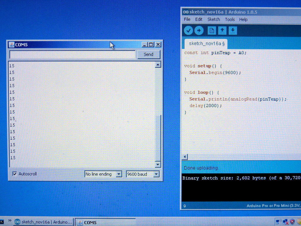
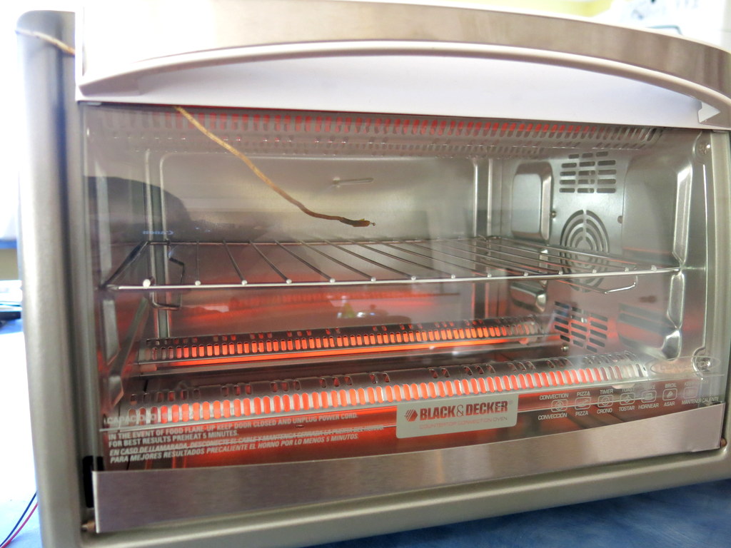
Now I’ve explained the motivation, let’s see how to go about implementing it. The first step is to learn to use V-USB. I started with the EasyLogger project downloaded from the V-USB website. It is based on the tiny45 mcu. The program reads a sensor (e.g. temperature or light) and presents itself as a USB keyboard to print out the sensor values to a host computer. This is an excellent starting point for me because USB keyboard is a standard HID-class device, and the project is simple enough that I can easily learn and make modifications.

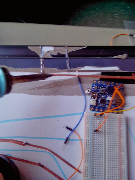
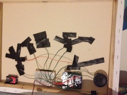
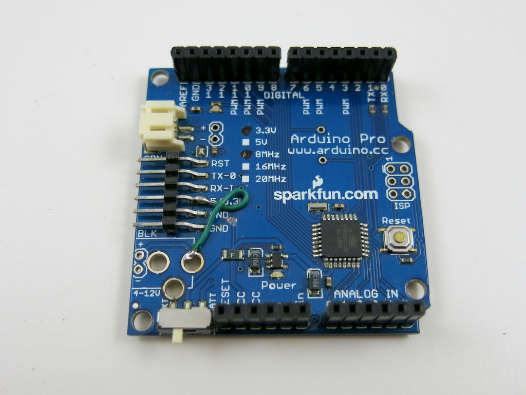
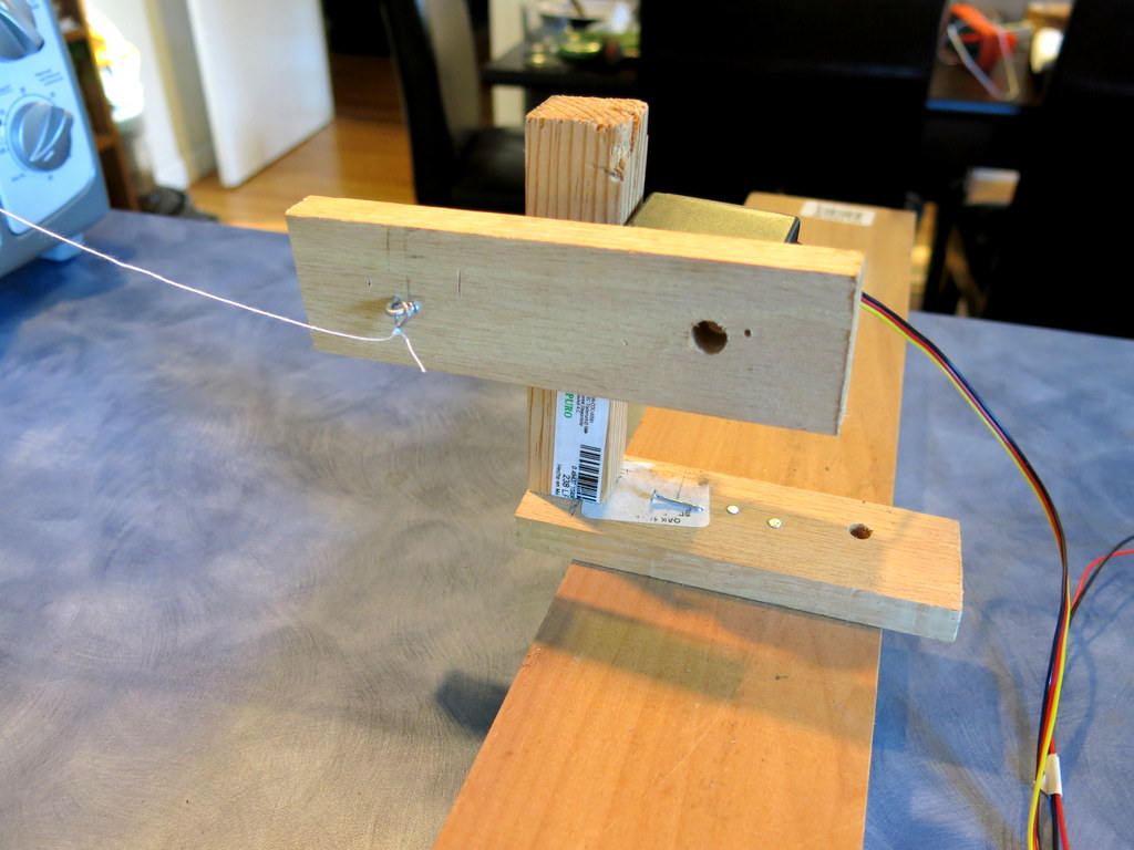
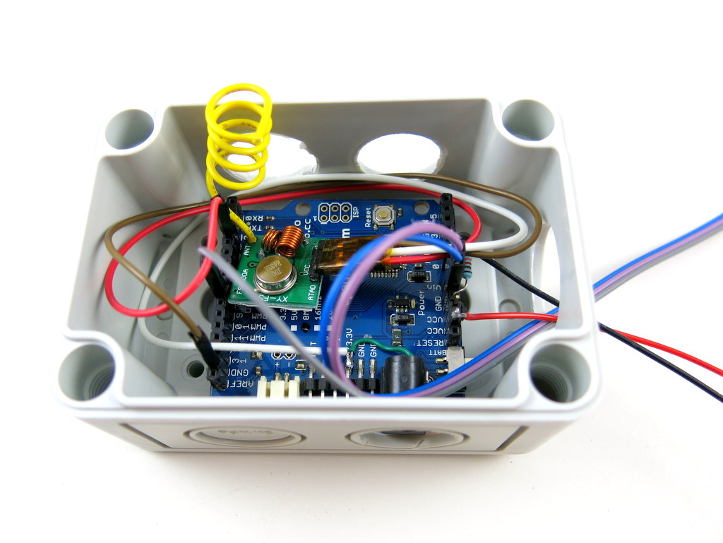
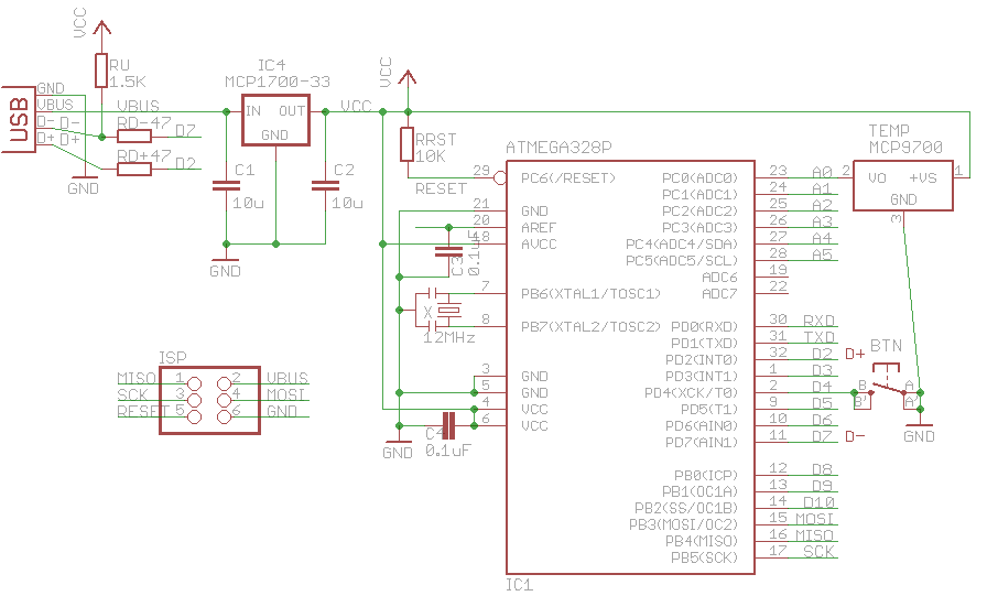
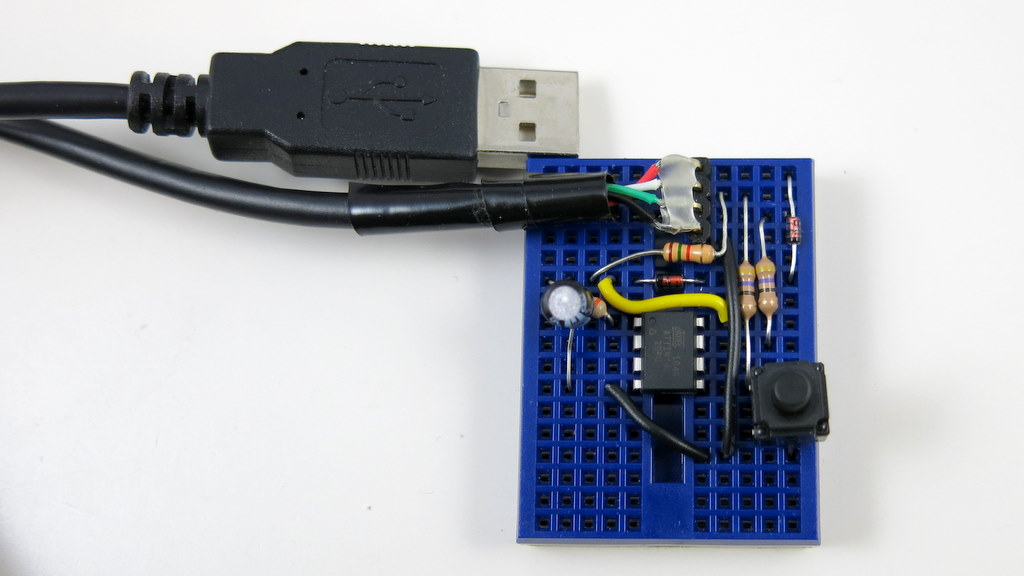
To adapt it to mega328, I first made a circuit based on USnoobie. Here is the schematic and my build of the circuit on a breadboard:

m328-vusbIMG_3287

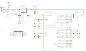
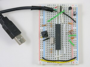
It’s a pretty standard V-USB setup. I assigned digital pin PD2 (INT0) to USB D+, pin PD7 to USB D-, and PD4 to a pushbutton. The pushbutton is used to enter bootloading mode. Specifically, if the button is pressed when the circuit is powered up, the bootloader is activated and the mcu will appear as a USBasp programmer. Different from USnoobie, I’ve decoupled this button from the D- line, so that I can use the button for general-purpose input (otherwise pressing the button will trigger the D- line). This requires changing the USnoobie code slightly to use pin PD4 for bootloading condition. Finally, I’ve also added a MCP9700 temperature sensor (you can replace it by any analog sensor such as photosensor) to analog pin ADC0 for testing later.

The next step is to modify the source code. First, change usbconfig.h to match the D+ and D- pin settings, specifically the following three macro defines:

#define USB_CFG_IOPORTNAME      D
/* */
#define USB_CFG_DMINUS_BIT      7
/* */
#define USB_CFG_DPLUS_BIT       2
/* */

Next, modify main.c. This step is pretty technical and tedious. It mainly involves changing register names to match mega328 (since the code was originally written for tiny45). Also, the calibrateOscillator(); function can be removed as the mega328 will be running on an external 12MHz clock.

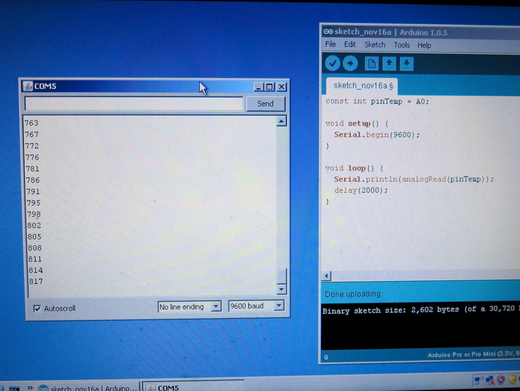
I also modified the Makefile in order to compile and flash the code for mega328. After a few tweaks here and there, the EasyLogger started working on my mega328! It can successfully output numerical values to a text editor through the USB port. This is very encouraging. If these steps don’t make much sense, you can take a look at the code below, and give it a try yourself.

Learning HID

HID stands for Human Interface Device. It’s a USB class designed primarily for keyboard, mice, joystick, and similar human interface devices. The nice thing about HID is that it’s supported on all operating systems. For example, on Windows, the system uses built-in HID driver to handle USB requests, so no driver installation is required. This is why when you plug in a keyboard or mice, you never have to install a driver (imagine how annoying it would be if you had to!).

To implement HID, you first will need to construct a HID descriptor, which describes the number of reports, and the size, meaning, and (optionally) value range of each report. For example, these reports can be the ASCII code of the pressed key, the x and y offsets, and button presses of the mouse. There are also more general-purpose reports like a buffer of bytes. This is what I will be using to transfer bytes in and out between the device and host. To be honest, the whole USB descriptor thing was very obscure to me in the beginning. I didn’t know if there is one correct way to define it, or it can be flexible. As it turns out, Linux is pretty forgiving about it, but Windows is not. After many trials and errors, I finally settled with this HID descriptor:

PROGMEM const char usbHidReportDescriptor[USB_CFG_HID_REPORT_DESCRIPTOR_LENGTH] = {    /* USB report descriptor */
    0x06, 0x00, 0xff,              // USAGE_PAGE (Generic Desktop)
    0x09, 0x01,                    // USAGE (Vendor Usage 1)
    0xa1, 0x01,                    // COLLECTION (Application)
    0x15, 0x00,                    //   LOGICAL_MINIMUM (0)
    0x26, 0xff, 0x00,              //   LOGICAL_MAXIMUM (255)
    0x75, 0x08,                    //   REPORT_SIZE (8)
    0x95, 0x08,                    //   REPORT_COUNT (8)
    0x09, 0x00,                    //   USAGE (Undefined)
    0x82, 0x02, 0x01,              //   INPUT (Data,Var,Abs,Buf)
    0x95, HIDSERIAL_INBUFFER_SIZE, //   REPORT_COUNT (32)
    0x09, 0x00,                    //   USAGE (Undefined)
    0xb2, 0x02, 0x01,              //   FEATURE (Data,Var,Abs,Buf)
    0xc0                           // END_COLLECTION
};

It contains an outgoing buffer of 8 bytes (to transfer data to the host) and an incoming buffer of 32 bytes (to receive data from the host). As I said above, Linux is pretty flexible about the descriptor — you can change it in many ways and it still works. Windows, however, is very strict — if you are not careful, it will simply refuse to recognize the device.

The next step is to write functions to handle the USB requests. For transferring data out, I used the usbSetInterrupt function, which allows sending data spontaneously to the host (i.e. whenever the device has something to report). (I should mention here that I wrote the code as an Arduino library called HIDSerial. So everything gets compiled in the Arduino software. You can certainly use avr-gcc to compile the code as well). I made HIDSerial an inherited class from Arduino’s Print class, so I can make use of the many available print functions (e.g. print a string, an integer, a floating point) in the class for serial printing need, without writing extra code. For transferring data in, I implemented the usbFunctionWrite function, as described in the V-USB Document Wiki.

Now, before I can test and debug the code, I need to have some minimal host software to communicate with the device. That’s what I will be describing next.

Write Host Software using Processing

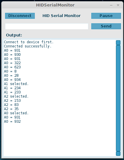
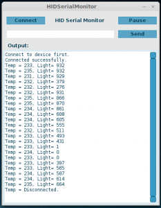
Going the HID route means the device will not appear as a standard serial COM port, so you can’t use the standard serial monitor to send and receive values. Instead, I will have to write host software myself. I can certainly do this in C or Java. But since I want to make the host software cross-platform, I have chosen to implement it in Processing, which allows me to easily export the program as standalone applications on all platforms. Long story short, to do this, I used HIDAPI library. It has all the goodies to handle communications with HID devices, such as finding a device, opening the device, reading from the device, and sending feature report to the device. Also, using the G4P library, you can easily build a GUI with buttons and text fields, and make the interface just like a standard serial monitor. Once the software is finalized, I can simply click on ‘Export Application’, and select all three platforms, and voilà, the host software is all set! Below are two screenshots of the HID serial monitor:

hidserialmonitor1hidserialmonitor2

Source Code

The source code of this project is available for download on my GitHub repository:

You can either do a git clone, or directly download the project as a zip file (see the Download .zip button on the right-hand side of the page). The folder contains circuit schematic, part list, Arduino library (HIDSerial), host software (HID serial monitor), and bootloader (optional, but recommended as it allows you to re-flash the microcontroller through USB, without any external programmer). The Arduino library consists of several starting examples, which are also demonstrated in the video above. I am sure there are bugs and issues with the code, but please feel free to leave comments and feedback below, in order for me to improve the code.

Limitations and Issues

The biggest limitation of this implementation is the data transfer speed — it’s much slower compared to a standard USB-serial converter. This will be an issue if you need to pump out data as fast as possible. But I figured that for the purpose of debugging, the transfer speed is usually not that critical. The software works pretty reliably in Linux, but I’ve found that on Windows, the host software starts to lose data after running for a while, so not all data get transferred correctly. Resetting the microcontroller and restarting the host software seem to get it back to work. I am still investigating the cause of this issue. It may still have to do with Windows being very strict with USB communication protocols. Perhaps the USB experts can take a look at the code and point me in the right direction.

Adapting the Code to Other AVRs

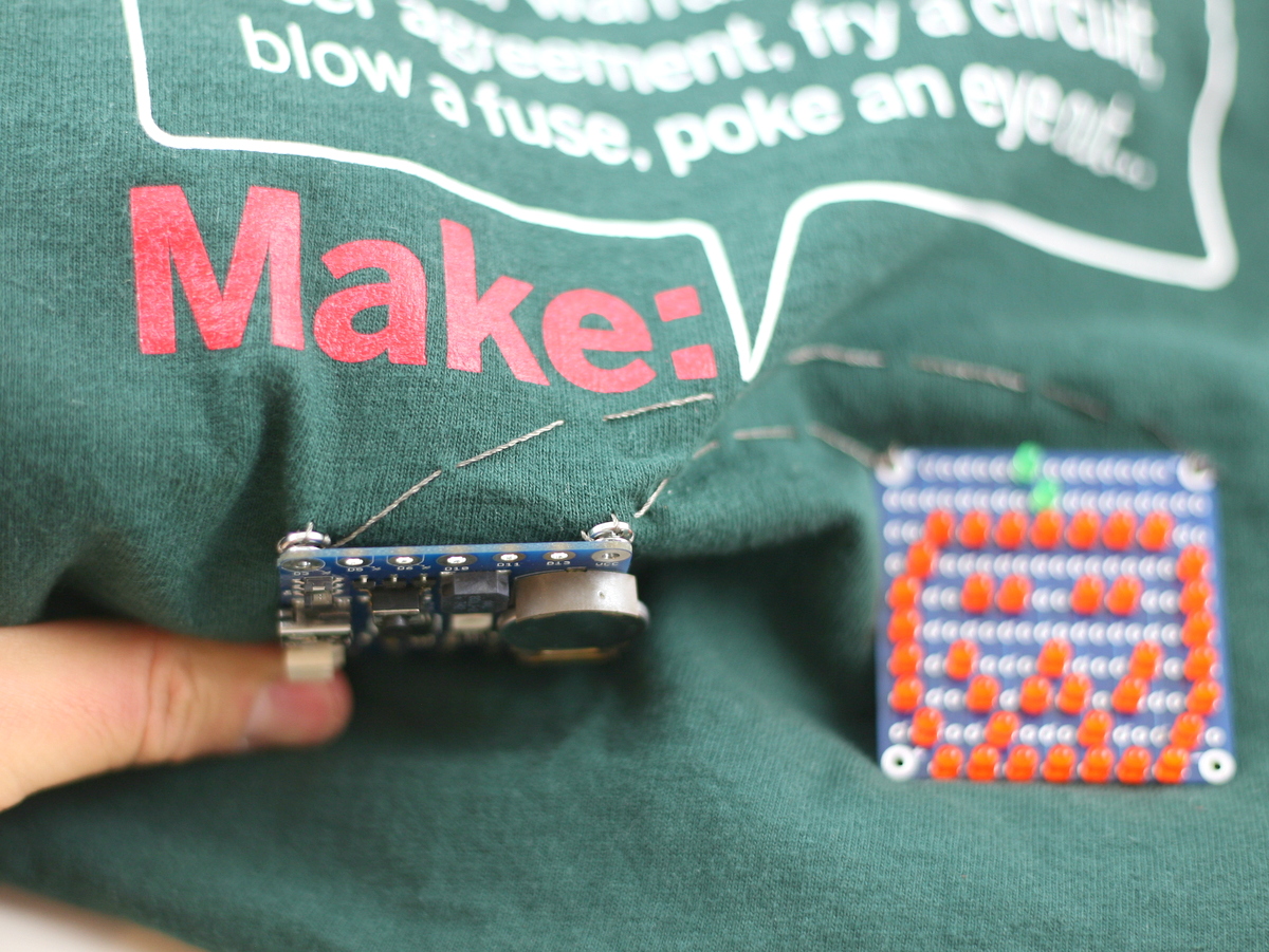
It’s relatively easy to adapt the code to other AVRs. For example, ATtiny45/85 is a popular V-USB platform, since it’s small, cheap, and has internal oscillator that can run at 16.5MHz, which meets the USB standard (so it saves a crystal and frees up two pins). By changing a couple of pin assignments in the source code, I was able to get the HID serial functions to work on tiny45. I really should do it on tiny85, since tiny45 has only 4KB flash space (even a simple demo would take more than 3.5K flash space). Here is a picture of the tiny45 breadboard build. You can even program tiny45 in the Arduino software by following the descriptions here.

IMG_3322

Thanks for reading the post. Feedback, comments, and questions are welcome.

OpenSprinkler Zone Expansion Board Upgraded to v1.1

One of the hallmarks of OpenSprinkler / OpenSprinkler Pi is the capability of expanding the number of zones. While the main controller can only interface with 8 zones, you can expand beyond 8 zones by daisy chaining Zone Expansion boards. Each expansion board adds another 8 zones. Because the zone expansion is implemented using shift registers, there is no hardware limitation on the total number of zones (although there is a software limitation due to the memory space required to store the information and data for each zone). This provides an economic way to implement a large number of zones. On commercial sprinkler controllers, zone expansion is relatively expensive, sometimes requiring you to upgrade to a new controller all together. On OpenSprinkler, if you need more zones, just buy more expansion boards. The software is designed to handle all zones in a consistent user interface.

Previously, the zone expansion board is based on the same PCB as the main controller, and they share the same enclosure. This makes it easy to use a consistent enclosure design for both. However, the zone expansion circuit is actually very simple (just a shift register, a couple of resistors, and eight triacs), so it’s no need to commission a PCB as large as the main controller for something that can be much smaller. So I’ve decided to give the expansion board an upgrade, to version 1.1, which uses a much smaller PCB footprint, and its own dedicated enclosure (based on Serpac WM011).

IMG_3017IMG_3014

The new version is just a little over half the size of the original one. So in the same amount of space you can almost fit two expansion boards. This is particularly useful for people who has a limited space to fit a main controller and one or more expansion boards.

In addition, the zone expansion cable has been upgraded to use a polarized connector. Specifically, the connector has a small bump at the top, which matches the notch on the cutout of the enclosure. This way, there is only one possible orientation to insert the cable connector, thus preventing incorrect orientation:

IMG_3011IMG_3013

The picture on the left above shows the polarized cutout on the expansion board, and the picture on the right shows a similar cutout on the upcoming injection molded OpenSprinkler enclosure. This can help avoid mistakes when inserting the expansion cable. A special note that this cable has different pin connections with the previous version of expansion boards. So you should NEVER use the polarized cable with previous versions of zone expansion boards, or you may risk damaging your main controller!

Finally, expansion board v1.1 has added a 10K pull-down resistor, which when coupled with OpenSprinkler 2.0, allows the main controller to automatically detect the number of zone expansion boards. This feature is already included in hardware design, but hasn’t been implemented in software yet. The basic principle is that the main controller has a 1.5K pull-up resistor, and each expansion board has a 10K pull-down resistor. When multiple expansion boards are linked together, the pull-down resistors are connected in parallel, thus changing the divided voltage. By using an analog pin (which is internally wired to the voltage division point), the controller can easily calculate how many boards are linked together. A very simple solution!

To conclude, here is a short summary of the new features on OpenSprinkler Zone Expansion Board v1.1:

  • Reduced form factor, and dedicated enclosure.
  • Polarized expansion cable connector.
  • Added pull-down resistor for automatic detection of the number of expansion boards.
  • Besides, the new expansion board retains the on-board PCB holes to fit one MOV per zone, and it works with both OpenSprinkler and OpenSprinkler Pi.

That’s all for the update. This new version is in stock and available for purchase at Rayshobby Shop. Same old price!

Announcing OpenSprinkler Pre-Release v2.0s (assembled version)

After a few weeks of shipping these ‘underground’, I am finally happy to spread the words around: the OpenSprinkler Pre-Release v2.0s is officially available for sale! Note that this is the SMT assembled version — we don’t have DIY 2.0 yet. As usual, the first question to ask is what’s new in this version?

  • Upgraded MCU: OpenSprinkler 2.0 uses ATmega644, which is twice as much as ATmega328 in all aspects (i.e. flash memory size, GPIO pins, RAM, EEPROM, perhaps price as well 🙂 ). This makes it possible to add new features that I have planned ahead (e.g. weather-based control, logging, interfacing with wireless devices etc.) We will no longer be constrained by the flash memory size, well, at least for a while.
  • Upgraded Switching Regulator: the switching regulator (for 24VAC->5VDC conversion) has been upgraded from MC34063 to LM2596, which is less noisy and capable of outputting higher current. As more users are powering WiFi adapters through OpenSprinkler’s USB port, it’s important to make the power conversion section robust. The same circuitry is now also used in OpenSprinkler Pi. Details about this change can be found in this blog post.
  • Added microSD Card Slot: microSD card is useful for expanding the storage size of a microcontroller. This s great for a lot of purposes, such as logging, storing a lot of sprinkler programs, Javascript files etc. A standard microSD card shares the SPI interface and requires only one extra GPIO pin to operate. Hence adding microSD card support is a no brainer!
  • Expansion Board Detection: this allows the main controller to automatically detect the number of zone expansion boards linked to the controller. Not so crucial, but neat. The implementation is actually quite simple: it uses a pull-up resistor on the main controller and one pull-down resistor on each expansion board to form a voltage divider. By checking the voltage using an analog pin, the mcu can easily calculate how many boards are linked.
  • Other Features: given the plentiful GPIO pins available on ATmega644, I’ve added support to adjust LCD contrast and backlight (using two PWM pins), a set of pin headers for plugging in an off-the-shelf RF transmitter (for interfacing with wireless devices). The other un-used pins are made available in the pinout area (including three analog pins, two interrupt pins, two digital pins, as well as TXD, RXD, SDA and SCL).

OK, that’s quite a detailed list of new features. Here is an annotated diagram of the actual hardware:

os20_component_diagram

Also, just for fun, a diagram that shows each module of the circuit and where they are located on the PCB:

os20_module_diagram

The reason I call this the Pre-Release 2.0 is that the official 2.0 will use the injection molded enclosures I blogged about in this post. While that is already in production at SeeedStudio, I can’t give a reliable estimate of how long it will take for the final products to arrive. There have already been multiple delays, so I won’t be surprised if there are more… Other than the difference in the enclosure design, the pre-release 2.0 hardware is the same as the final 2.0.

If you are wondering what I mean by ‘shipping these underground’ at the beginning of the post — we’ve been automatically upgrading the recent orders of assembled OpenSprinkler v1.4s to v2.0s. Why not make it public? Well, there are several reasons. The first is that due to the Maker Faire and the vacation after that, I haven’t had time to finish the documentations, and I’m reluctant to officially release a product when the documentations are not ready yet. Second, I’ve been experimenting with minor changes of the 2.0 design, and we’ve been shipping several small batches, each with slight different hardware design. This is an important process to get user feedback, and to iron out all engineering issues before the official release. Finally, as many users have been waiting for 2.0, I don’t want to suddenly get into an overload situation, where the number of orders exceed our capacity to process them.

In terms of software, OpenSprinkler 2.0 is currently flashed with firmware 2.0.0, which is functionally the same as firmware 1.8.3, except for the additional options such as LCD contrast and backlight, and the support for a higher number of expansion boards and programs. More exciting firmware features will be gradually added over time. Also, starting from firmware 2.0.0, the source code can be compiled in Arduino 1.x (latest stable version is 1.0.5), and this is also the recommended Arduino version to compile OpenSprinkler code. I will continue to provide a VirtualBox image which has everything needed for compilation set up and ready to go.

The final bit of news: if you are interested in DIY 2.0, unfortunately that won’t be available for at least a couple of months. The delay is partly because the new injection molded enclosures are not ready yet (there is no space in the current enclosure to fit all through-hole components), and partly because there are a few design decisions I haven’t ironed out yet. So at least for a couple of months we will keep offering DIY 1.42u for anyone who wants to build OpenSprinkler from scratch.

So much for the announcement of OpenSprinkler Pre-Release 2.0. Feel free to leave your comments and suggestions below, or at the Rayshobby Forum. Thanks!