OpenSprinkler Mobile Web App Instructions (with Video)


Update: OpenSprinkler new mobile app (native version) is now available on all platforms. Search ‘opensprinkler’ in iOS App Store, Android Play Store, or Windows Phone Store, then download and install the app. Additional details can be found in this blog post.


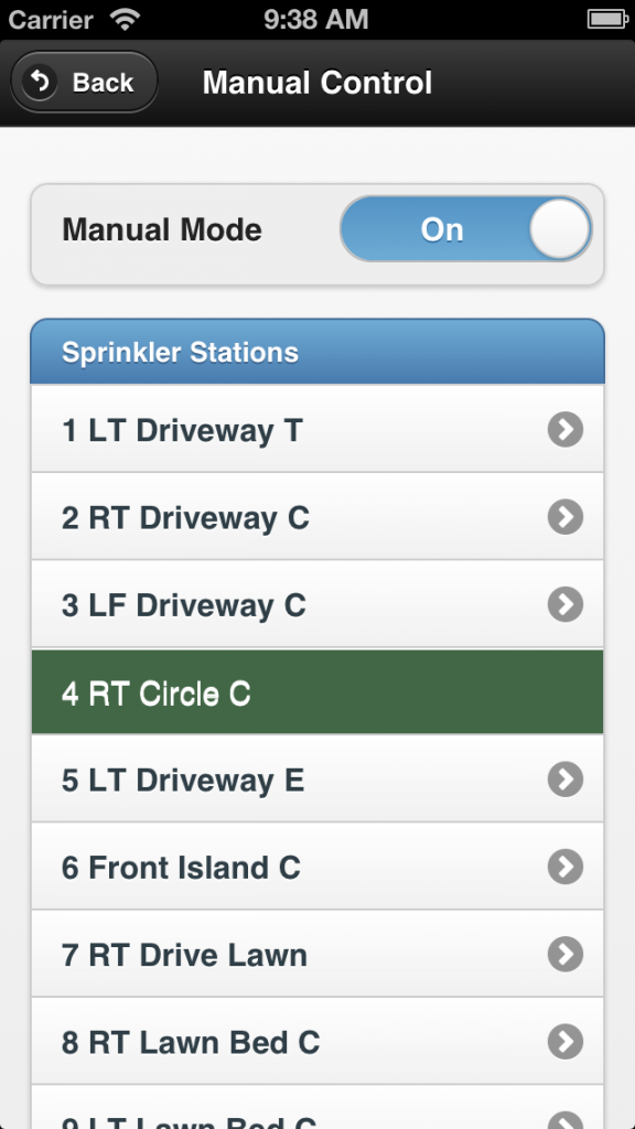
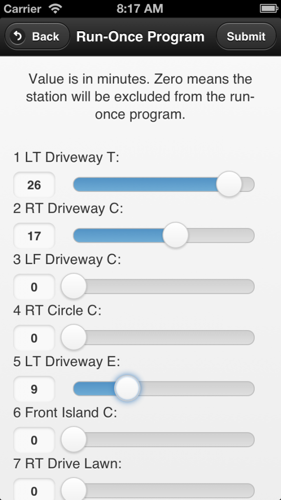
In this blog post, I will walk you through the basic steps to set up and use the OpenSprinkler mobile web app developed by Samer Albahra. I’d like to thank Samer for making this app available, and credits should be attributed to him. Initially I was planning to write a long post with textual instructions. But then I felt this app is such a significant contribution that it deserves its own video tutorial. So please take a look at the video below first. As the video is already quite long, I will keep the textual information short, with only a summary of the necessary steps, download links, and pointers to resources. Since the app is a work in progress, feel free to leave your comments and suggestions at the Rayshobby Forum.


Prerequisites

In order to use this app, you will need a working OpenSprinkler setup, such as

  • OpenSprinkler 1.x running firmware version 1.8.2 or above (note: firmware 1.8.3 preferred);
  • or OpenSprinkler 2.0 running firmware version 2.0.0 or above;
  • or OpenSprinkler Pi any version running Dan’s interval_program (equivalent to firmware 1.8.2).

If you have OpenSprinkler 1.x with firmware earlier than 1.8.2, please follow the Firmware Update Instructions to re-flash the microcontroller with the latest firmware.

Also, if you are not familiar with the concept of a mobile web app, please take a look at my previous post about the app. Simply speaking, it’s an app that runs in a browser. It’s somewhat slower than a native app, but the biggest advantage is that it’s cross-platform (i.e. same app runs on both iOS, Android, etc., even desktop browsers). By adding the web link to home screen, the app will appear like a true native app.

NOTE to keep in mind: the app provides an alternative front end to the OpenSprinkler controller. The default front end, which is the controller’s webpage (accessed by typing in the controller’s ip in a browser), is still available and functioning. Any operation you apply through the app will also be reflected in the default front end.


Version 1: Hosted App on Rayshobby.net

Samer made the app available in two versions. The first is a hosted app available at the following url:

http://rayshobby.net/apps/sprinklers/

Type this in the browser on your smartphone, tablets, or even desktop computer, and you can start using it immediately. However, before you proceed, make sure you have port forwarding set up on your router. See below.

Port Forwarding: because the hosted app needs to communicate with your OpenSprinkler through HTTP commands, your controller must be accessible by the rayshobby server. To do so, you need to set up port forwarding on your router, so that an external HTTP request to your router will be mapped to your OpenSprinkler controller. This requires knowing your OpenSprinkler’s IP address and port number (default is 80). Please refer to your router’s user manual for instructions. In addition, you can use dynamic DNS service (such as dyn.com, freeDNS etc.) to set up a DNS name for your router (i.e. an easy-to-remember name such as rayshobby.dyndns-web.com instead of the router’s IP). Most routers support dynamic DNS service as well.

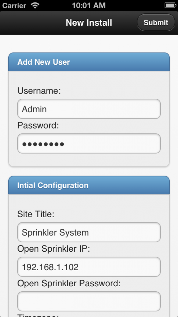
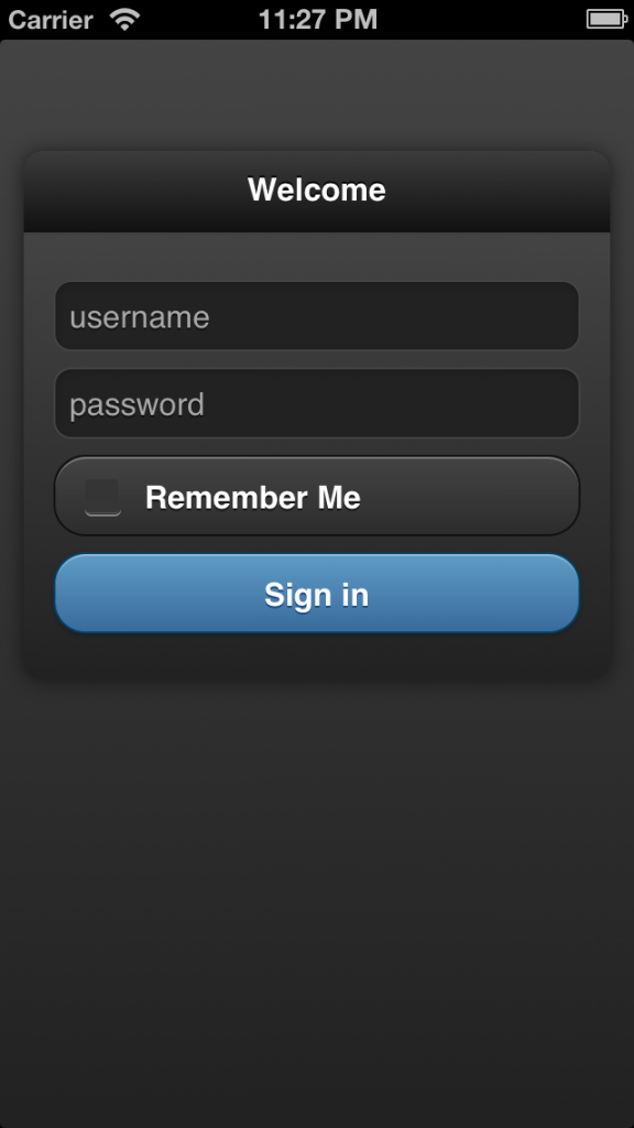
Logging in: going back to the app, on the log-in page, type in your router’s IP (or dynamic DNS), optionally followed by the port number (if it’s not the default 80), and your OpenSprinkler’s access password (the default password is ‘opendoor’). Then click on the button.

Add Link to Homescreen: most mobile browsers support adding (or bookmarking) a link to homescreen. This creates a homescreen icon, which you can simply click to start the app each time.

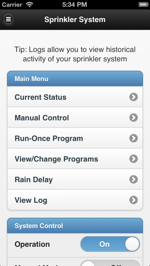
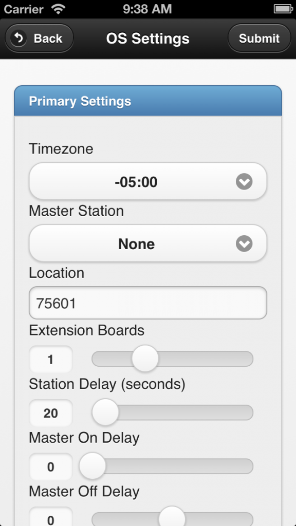
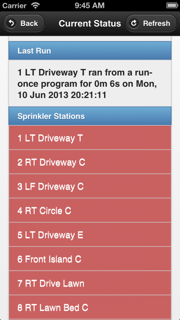
Features: the app has implemented all features available on the latest OpenSprinkler firmware. It provides a more stylish and intuitive interface than the default front end. For example, you can use slidebars to set values, there is a status bar that shows the currently running station with count-down timer, the app’s program preview provides an easy way to switch to a different day, everything is optimized for mobile viewing experience, and finally since the app is a front end itself it does not require external Javascript as required by the default front end. Please follow the video tutorial above and try out the app yourself. Most of the features are self-explanatory.

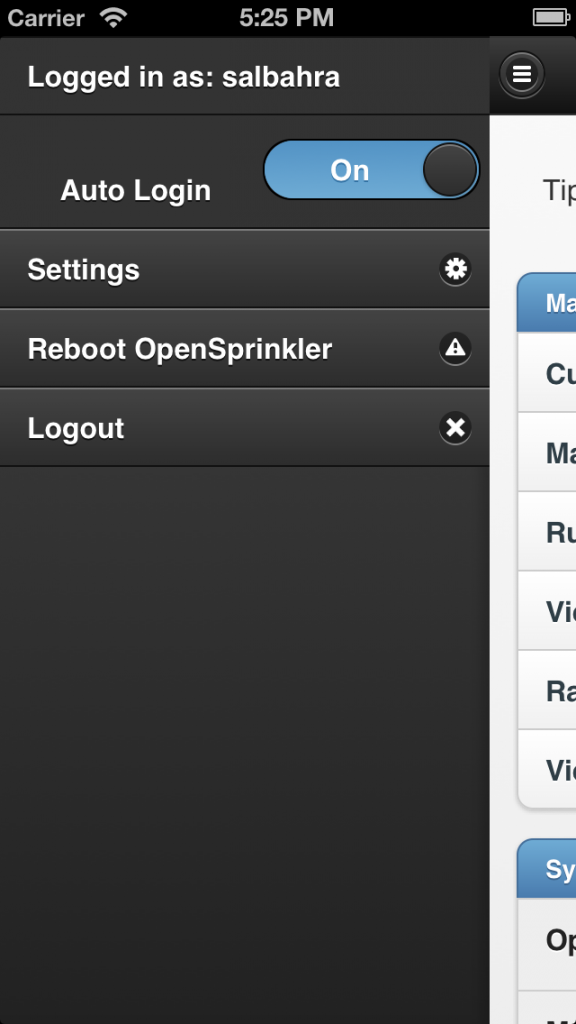
Donation: Samer wrote the app and shared it for free. I can’t thank him enough for making this app available and so polished. If you like the app, please consider donating some money to support his work. The donation link is available on the app’s ‘About’ page (accessible by clicking the control panel button at the upper-left corner of the app).

Summary: to summarize, in order to use the hosted web app, all you need is to set up port forwarding on your router, and use the hosted web app’s url above. That’s it!


Version 2: Self-Installed App on A Local Web Server

The second version is a self-installed app that requires using a local web serer. Most of the features in the second version are shared with the hosted web app above, however, by using a local web server you gain two additional features that may be very useful: logging, and weather-based rain delay.

Installation: for installation, simply follow the instructions on my previous post about the web app, particularly the How to Set it Up (using Raspberry Pi as example) section.

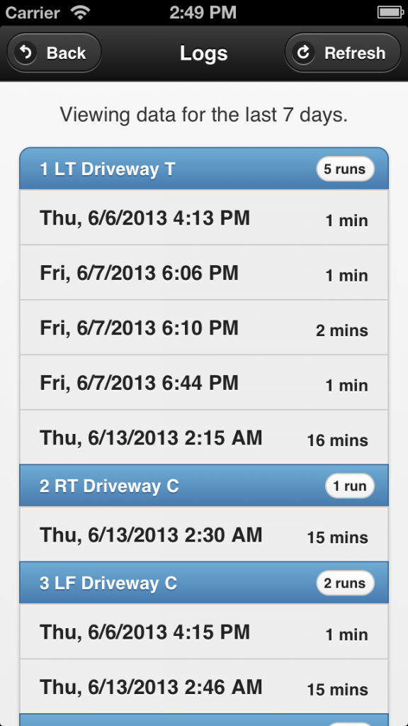
Logging Feature: the self-installed app records stations runs and keeps the history of station runs in a log file. On the app’s homepage you will see a button. Clicking on it brings out the log view, which categorizes log data by station names.

Weather-based Rain Delay: having a local web server also allows weather-based rain delay. This feature is developed by Andrew Shilliday (thank you, Andrew!). Basically, it’s a script that periodically pulls data from Yahoo Weather API (using your location information), and enforces rain delay if certain weather conditions are met. Technically, the data from Yahoo Weather contains a condition code that tells the local weather condition (e.g. showers, thunderstorm etc.). The script is associated with a data file that defines the amount of rain delay hours when a certain condition code is detected. For installation and setup instructions, please refer to Andrew’s GitHub page:

https://github.com/andrewshilliday/OpenSprinkler-WebRainDelay

This is a work in progress, and we are planning to integrate this feature into the OpenSprinkler firmware so that in the future it will not need installation any more.


Resources and Links

I am really glad to see these wonderful user contributions. They tremendously help make OpenSprinkler a better product, and I learned a lot through the forum discussions, which in turn inspired new ideas. Below I list the currently active forum threads that are related to the mobile web app development and the weather feature:

We are actively working on making the weather-based control a firmware feature. If you have ideas and suggestions, please feel free to leave them at the forum. Thanks!
Announcing OpenSprinkler Pi v1.2

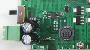
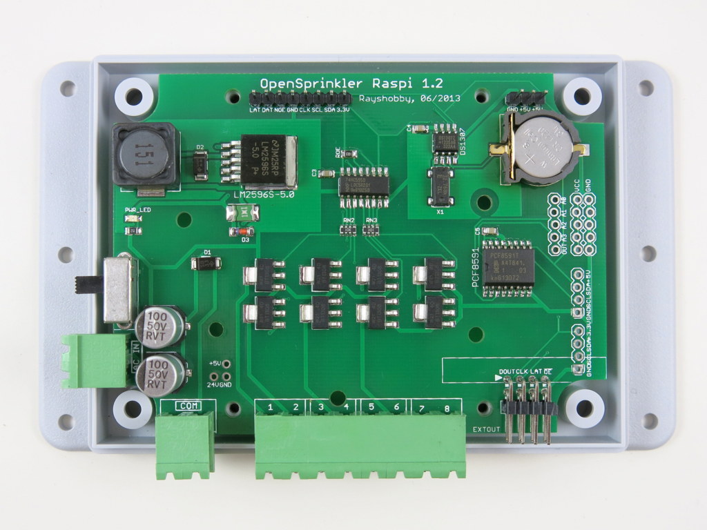
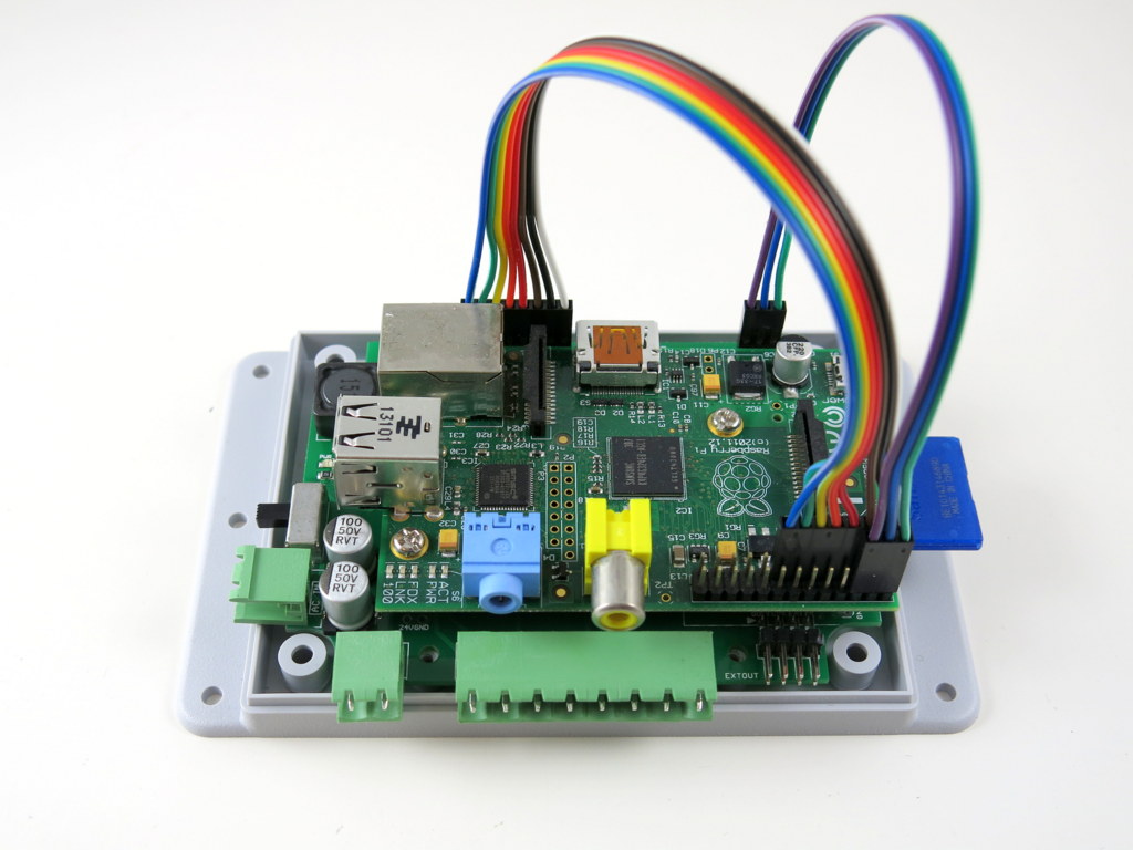
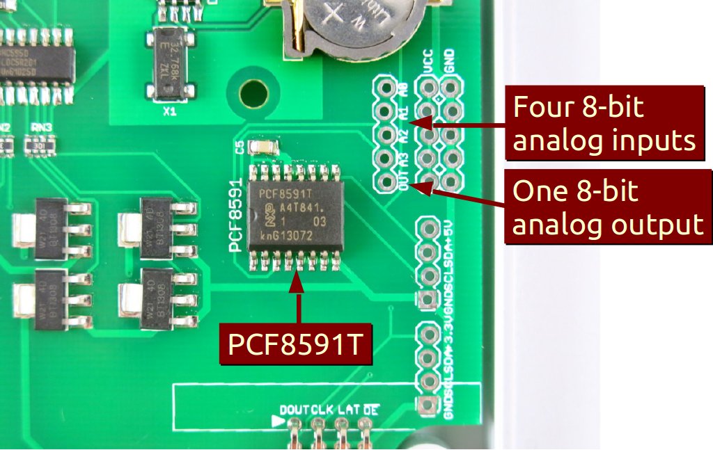
Hi, this is a new product post for OpenSprinkler Pi (OSPi) v1.2. Since its original release, OSPi has become a very popular product. This version is a minor revision. The main change compared to version 1.1 is the addition of a PCF8591T 8-bit A/D D/A converter, which provides four independent 8-bit analog input pins, and one 8-bit analog output pin. The reason this has been added is that Raspberry Pi (RPi)’s GPIO pins do not have built-in ADC capability. In order to interface with analog sensors (such as soil moisture sensor, light sensor etc.), you would need an ADC unit. The addition of the PCF8591T chip allows OSPi to provide on-board analog inputs as well as output. This makes it more convenient for your prototyping need. Other than this, the rest of the circuit is pretty much the same as before, with 24V AC to 5V DC switching regulator (based on LM2596S), DS1307 RTC and backup battery, 74HC595 shift register and triacs. Here are two pictures of the OSPi v1.2 board:

IMG_0004IMG_0008

If you Google ‘RPi ADC’ you will find plenty of choices of ADC modules and tutorials on how to get them to work with RPi. Why did I pick PCF8591T? There are several reasons. First, it’s low-cost: volume pricing is just a couple of dollars per piece. Second, it provides four independent A/D channels, and one D/A channel. This means you can use one chip to interface with 4 different analog sensors, and additionally you can get one channel of analog output. According to the datasheet, the analog output is implemented with resistor divider chain, which is sometimes a better choice than PWM. Also, it uses I2C interface, so it doesn’t require any extra GPIO pins from RPi. Overall it’s a very attractive choice. The main downside is that it’s only 8-bit. This means the analog input value is on a resolution of 0 to 255, same with analog output. A lot of the other chips provide at least 10 bits of precision. But I figured that 8-bit is sufficient in many cases, so I settled with this choice.

The chip, together with analog pinouts, are located on the right-hand side of the board:
IMG_0006_annotated

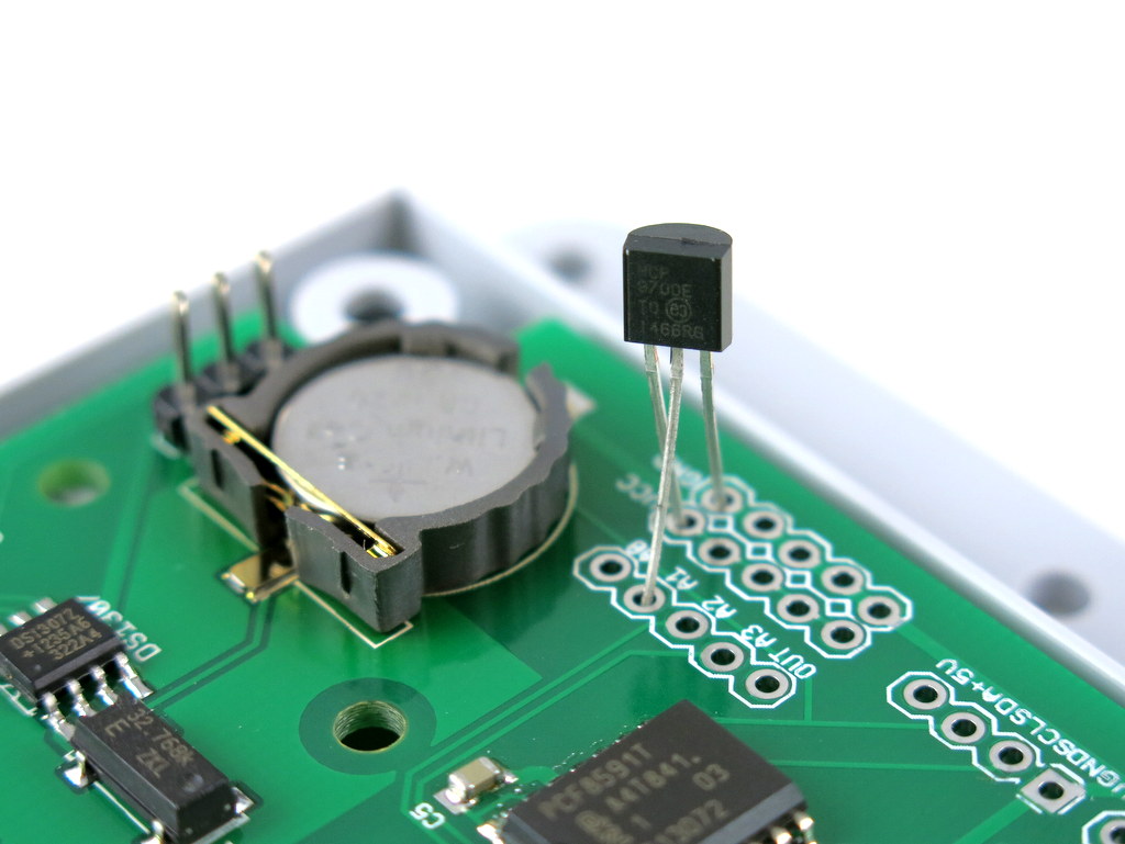
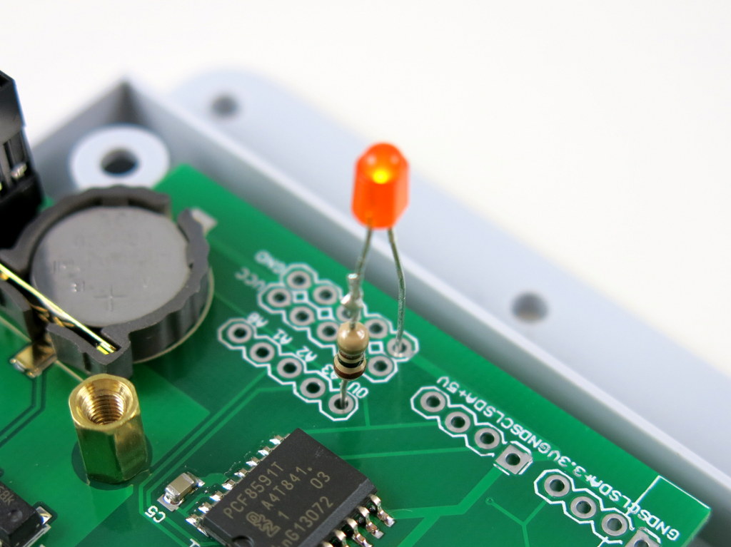
For convenience, I’ve also provided a separate pair of VCC and GND pinouts for each analog channel. The picture on the left below is an example of plugging in a MCP9700 temperature sensor directly to the pinouts; and the picture on the right below shows an LED (with current limiting resistor) plugged into the analog output channel, to allow programmable control of the LED brightness.

IMG_0005IMG_0009

Suppose this gets you interested, the next question is how to program RPi to talk to the ADC chip? Fortunately there are plenty of tutorials online. In particular, I found the following posts very useful:

If you are confused and just want a quick demo. Here is a short tutorial to get you started.

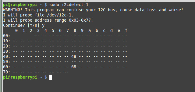
First, run sudo i2cdetect 1 to check if the PCF8591T chip is detected. (Note, if you own RPi rev. 1 you should run sudo i2cdetect 0 instead). You should then see a printout like the following. This shows it has detected two I2C devices, one is at address 0x68 (that’s the DS1307 RTC), and one 0x48 (this is PCF8591T).
pcf8591t_i2cdetect

Next, you can use the i2cget command to read analog values from a particular channel. For example, run
sudo i2cget -y 1 0x48
repeatedly to sample the analog value from channel 0 (pin A0). To change to channel 1 instead, run
sudo i2cset -y 1 0x48 0x01
and then if you run sudo i2cget -y 1 0x48 that will return sampled value of channel 1, and so on.

To enable analog output, use the i2cset command. For example:
sudo i2cset -y 1 0x48 0x40 0xff
where 0xff is the 8-bit analog output value. You can change it to any value between 0x00 to 0xff to enable 256 grades of values. Since the chip is powered by 3.3V supply, that will translate to an analog output from 0V to 3.3V linearly.

The above use shell commands as an example to interface with the chip. There are also WiringPi and Python code examples which can do the same. When I get time I will write a more complete tutorial. For now, try to explore on your own 🙂

OpenSprinkler Pi v1.2 is immediately available for purchase at Rayshobby Shop, at the same old price.

OpenSprinkler Zone Expansion Board Upgraded to v1.1

One of the hallmarks of OpenSprinkler / OpenSprinkler Pi is the capability of expanding the number of zones. While the main controller can only interface with 8 zones, you can expand beyond 8 zones by daisy chaining Zone Expansion boards. Each expansion board adds another 8 zones. Because the zone expansion is implemented using shift registers, there is no hardware limitation on the total number of zones (although there is a software limitation due to the memory space required to store the information and data for each zone). This provides an economic way to implement a large number of zones. On commercial sprinkler controllers, zone expansion is relatively expensive, sometimes requiring you to upgrade to a new controller all together. On OpenSprinkler, if you need more zones, just buy more expansion boards. The software is designed to handle all zones in a consistent user interface.

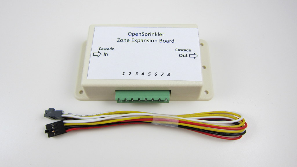
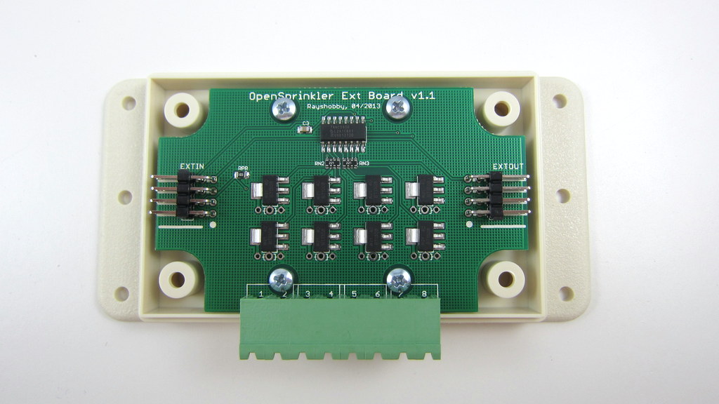
Previously, the zone expansion board is based on the same PCB as the main controller, and they share the same enclosure. This makes it easy to use a consistent enclosure design for both. However, the zone expansion circuit is actually very simple (just a shift register, a couple of resistors, and eight triacs), so it’s no need to commission a PCB as large as the main controller for something that can be much smaller. So I’ve decided to give the expansion board an upgrade, to version 1.1, which uses a much smaller PCB footprint, and its own dedicated enclosure (based on Serpac WM011).

IMG_3017IMG_3014

The new version is just a little over half the size of the original one. So in the same amount of space you can almost fit two expansion boards. This is particularly useful for people who has a limited space to fit a main controller and one or more expansion boards.

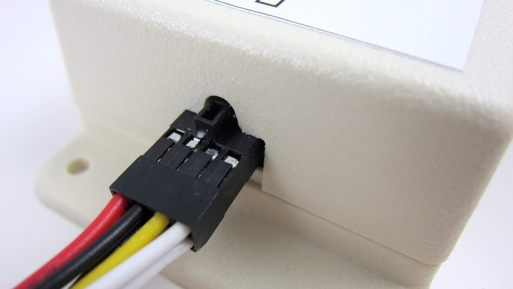
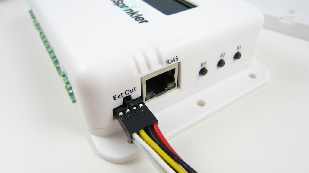
In addition, the zone expansion cable has been upgraded to use a polarized connector. Specifically, the connector has a small bump at the top, which matches the notch on the cutout of the enclosure. This way, there is only one possible orientation to insert the cable connector, thus preventing incorrect orientation:

IMG_3011IMG_3013

The picture on the left above shows the polarized cutout on the expansion board, and the picture on the right shows a similar cutout on the upcoming injection molded OpenSprinkler enclosure. This can help avoid mistakes when inserting the expansion cable. A special note that this cable has different pin connections with the previous version of expansion boards. So you should NEVER use the polarized cable with previous versions of zone expansion boards, or you may risk damaging your main controller!

Finally, expansion board v1.1 has added a 10K pull-down resistor, which when coupled with OpenSprinkler 2.0, allows the main controller to automatically detect the number of zone expansion boards. This feature is already included in hardware design, but hasn’t been implemented in software yet. The basic principle is that the main controller has a 1.5K pull-up resistor, and each expansion board has a 10K pull-down resistor. When multiple expansion boards are linked together, the pull-down resistors are connected in parallel, thus changing the divided voltage. By using an analog pin (which is internally wired to the voltage division point), the controller can easily calculate how many boards are linked together. A very simple solution!

To conclude, here is a short summary of the new features on OpenSprinkler Zone Expansion Board v1.1:

  • Reduced form factor, and dedicated enclosure.
  • Polarized expansion cable connector.
  • Added pull-down resistor for automatic detection of the number of expansion boards.
  • Besides, the new expansion board retains the on-board PCB holes to fit one MOV per zone, and it works with both OpenSprinkler and OpenSprinkler Pi.

That’s all for the update. This new version is in stock and available for purchase at Rayshobby Shop. Same old price!

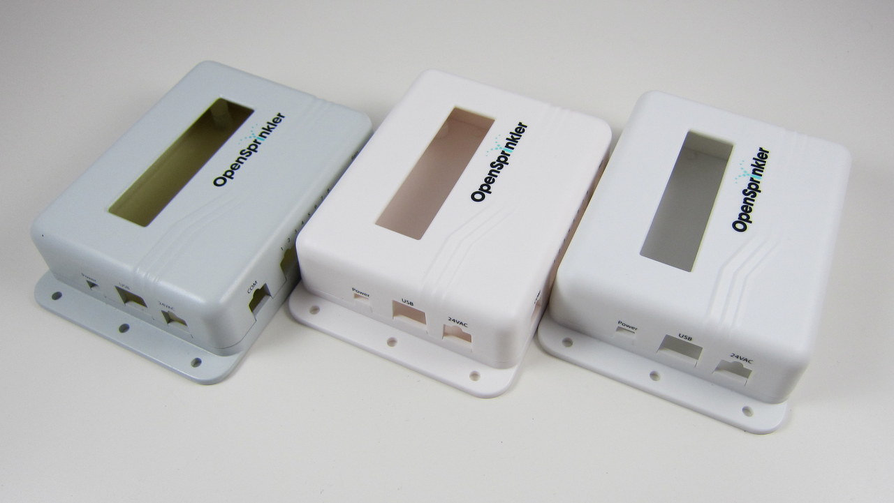
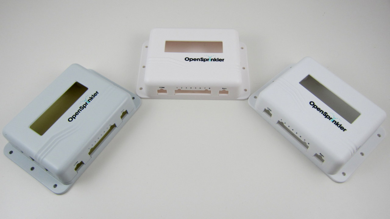
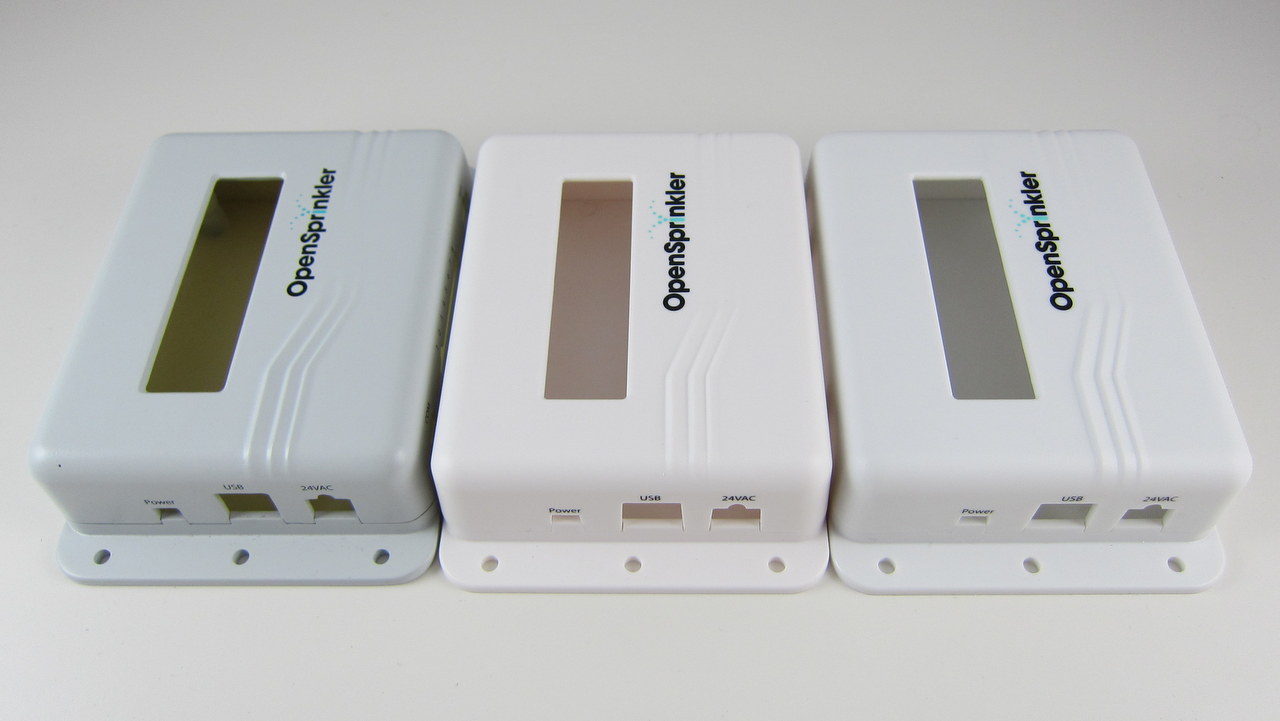
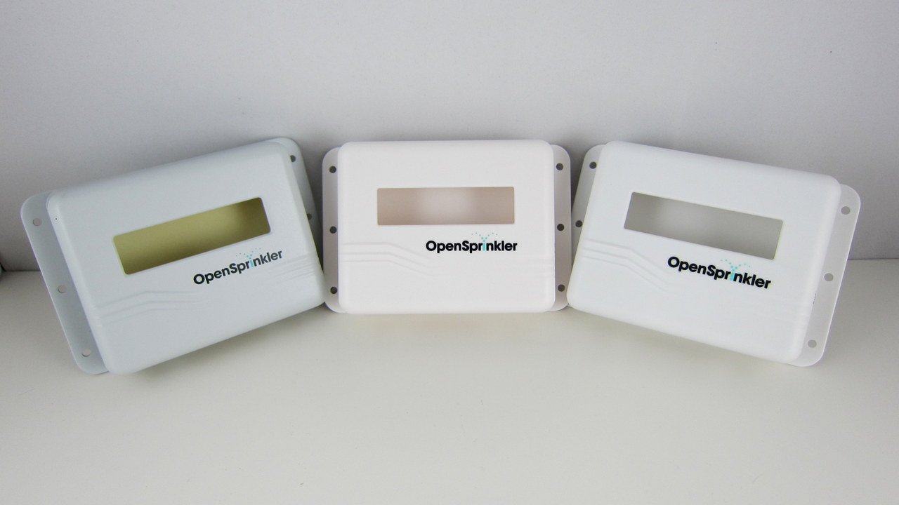
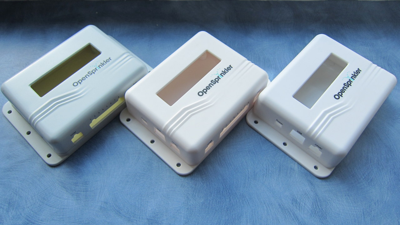
Moment of decision: which color do you prefer for the OpenSprinkler enclosure?

The final sample of the injection molded enclosure has arrived. Very exciting! The moment of decision: I’ve got three samples, each with a slightly different color. I’ve taken a few picture of all three side by side. The differences are subtle, but basically the first one (left) is more gray-ish, the second one (middle) is closer to milk white, the third one (right) is closer to pure white. Please vote for your favorite color in the comments section below (you can either use 1, 2, 3, or left, middle, right, or anything un-ambigious). I’ve only got a couple of days to give them my final decision, so please vote as quickly as you can. Thanks!

IMG_3003-001

IMG_3006-001

IMG_3005-001

IMG_3004-001

IMG_3000-001

Announcing OpenSprinkler Pre-Release v2.0s (assembled version)

After a few weeks of shipping these ‘underground’, I am finally happy to spread the words around: the OpenSprinkler Pre-Release v2.0s is officially available for sale! Note that this is the SMT assembled version — we don’t have DIY 2.0 yet. As usual, the first question to ask is what’s new in this version?

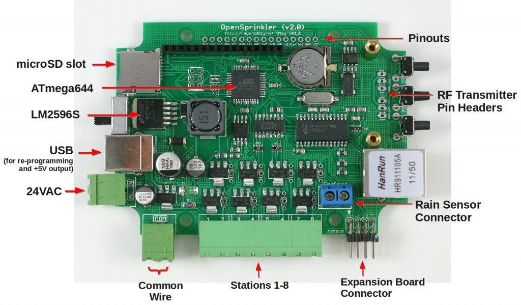
  • Upgraded MCU: OpenSprinkler 2.0 uses ATmega644, which is twice as much as ATmega328 in all aspects (i.e. flash memory size, GPIO pins, RAM, EEPROM, perhaps price as well 🙂 ). This makes it possible to add new features that I have planned ahead (e.g. weather-based control, logging, interfacing with wireless devices etc.) We will no longer be constrained by the flash memory size, well, at least for a while.
  • Upgraded Switching Regulator: the switching regulator (for 24VAC->5VDC conversion) has been upgraded from MC34063 to LM2596, which is less noisy and capable of outputting higher current. As more users are powering WiFi adapters through OpenSprinkler’s USB port, it’s important to make the power conversion section robust. The same circuitry is now also used in OpenSprinkler Pi. Details about this change can be found in this blog post.
  • Added microSD Card Slot: microSD card is useful for expanding the storage size of a microcontroller. This s great for a lot of purposes, such as logging, storing a lot of sprinkler programs, Javascript files etc. A standard microSD card shares the SPI interface and requires only one extra GPIO pin to operate. Hence adding microSD card support is a no brainer!
  • Expansion Board Detection: this allows the main controller to automatically detect the number of zone expansion boards linked to the controller. Not so crucial, but neat. The implementation is actually quite simple: it uses a pull-up resistor on the main controller and one pull-down resistor on each expansion board to form a voltage divider. By checking the voltage using an analog pin, the mcu can easily calculate how many boards are linked.
  • Other Features: given the plentiful GPIO pins available on ATmega644, I’ve added support to adjust LCD contrast and backlight (using two PWM pins), a set of pin headers for plugging in an off-the-shelf RF transmitter (for interfacing with wireless devices). The other un-used pins are made available in the pinout area (including three analog pins, two interrupt pins, two digital pins, as well as TXD, RXD, SDA and SCL).

OK, that’s quite a detailed list of new features. Here is an annotated diagram of the actual hardware:

os20_component_diagram

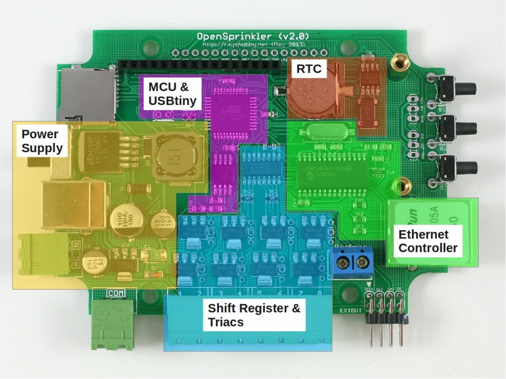
Also, just for fun, a diagram that shows each module of the circuit and where they are located on the PCB:

os20_module_diagram

The reason I call this the Pre-Release 2.0 is that the official 2.0 will use the injection molded enclosures I blogged about in this post. While that is already in production at SeeedStudio, I can’t give a reliable estimate of how long it will take for the final products to arrive. There have already been multiple delays, so I won’t be surprised if there are more… Other than the difference in the enclosure design, the pre-release 2.0 hardware is the same as the final 2.0.

If you are wondering what I mean by ‘shipping these underground’ at the beginning of the post — we’ve been automatically upgrading the recent orders of assembled OpenSprinkler v1.4s to v2.0s. Why not make it public? Well, there are several reasons. The first is that due to the Maker Faire and the vacation after that, I haven’t had time to finish the documentations, and I’m reluctant to officially release a product when the documentations are not ready yet. Second, I’ve been experimenting with minor changes of the 2.0 design, and we’ve been shipping several small batches, each with slight different hardware design. This is an important process to get user feedback, and to iron out all engineering issues before the official release. Finally, as many users have been waiting for 2.0, I don’t want to suddenly get into an overload situation, where the number of orders exceed our capacity to process them.

In terms of software, OpenSprinkler 2.0 is currently flashed with firmware 2.0.0, which is functionally the same as firmware 1.8.3, except for the additional options such as LCD contrast and backlight, and the support for a higher number of expansion boards and programs. More exciting firmware features will be gradually added over time. Also, starting from firmware 2.0.0, the source code can be compiled in Arduino 1.x (latest stable version is 1.0.5), and this is also the recommended Arduino version to compile OpenSprinkler code. I will continue to provide a VirtualBox image which has everything needed for compilation set up and ready to go.

The final bit of news: if you are interested in DIY 2.0, unfortunately that won’t be available for at least a couple of months. The delay is partly because the new injection molded enclosures are not ready yet (there is no space in the current enclosure to fit all through-hole components), and partly because there are a few design decisions I haven’t ironed out yet. So at least for a couple of months we will keep offering DIY 1.42u for anyone who wants to build OpenSprinkler from scratch.

So much for the announcement of OpenSprinkler Pre-Release 2.0. Feel free to leave your comments and suggestions below, or at the Rayshobby Forum. Thanks!

A Mobile Web App for OpenSprinkler and OpenSprinkler Pi


Update: OpenSprinkler new mobile app (native version) is now available on all platforms. Search ‘opensprinkler’ in iOS App Store, Android Play Store, or Windows Phone Store, then download and install the app. Additional details can be found in this blog post.


I am very excited to announce that a mobile web app for OpenSprinkler and OpenSprinkler Pi is now available, thanks to the generous contributions by Samer Albahra. After playing with the app for a while, I am quite pleased with the polished user interface. The only thing I want to say is it’s absolutely amazing! I would highly recommend those who are interested in a mobile app to give it a try. This blog post is a brief introduction to the app. For details, please refer to Samer’s write-up:

Before I begin, let me summarize some of the highlights of this development:

  • Cross-platform: the same web app runs on iOS, Android, as well as Desktop browsers. Also, the app is self-contained and does not rely on external Javascripts (so you can use it to access OpenSprinkler without Internet connection).
  • Supports the complete set of features in OpenSprinkler firmware 1.8.3 (and equivalently 2.0.0 for v2.0 hardware). Supports both OpenSprinkler and OpenSprinkler Pi (running the interval_program ported by Dan).
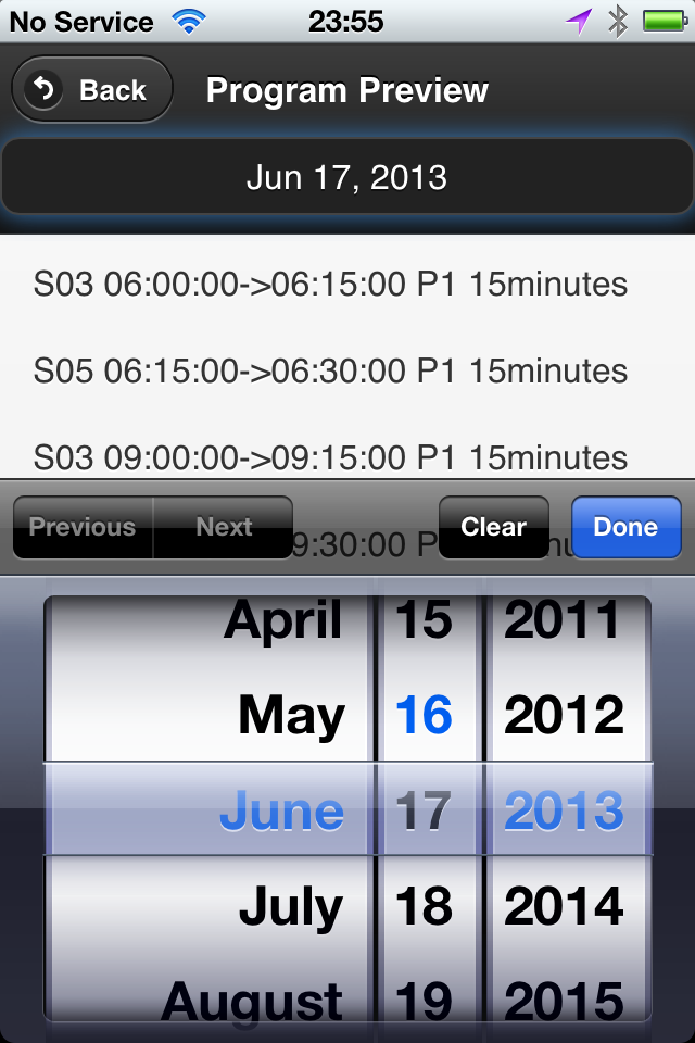
  • Supports additional features including logging and days selection in program preview.

The main requirement to enable this web app is an HTTP server with PHP support. You can either use a desktop server, or a Raspberry Pi (instructions given below), or an external server. For OpenSprinkler Pi users: the same RPi that drives your OSPi can be used as the HTTP server, so no additional RPi needed!

What’s a Mobile Web App?

Since the beginning of OpenSprinkler, requests for an iPhone or Android app have never stopped. To be frank, I have never written a mobile app myself. When writing the firmware for OpenSprinkler, I did consider a few tricks to make the webpage look a little nicer on a mobile browser, but the interface is still evidently written by an engineer, namely me 🙂 So far there have been a couple of efforts, mostly by OpenSprinkler users, to write iPhone apps (which I will blog about later). I am not aware of any effort to write Android apps.

So what’s a mobile web app? Simply speaking, it’s a webpage which appears like an app. Mobile webpages are not a new thing: when you use your phone or any mobile device to browse webpages, such as a bank’s homepage, the server will automatically detect what kind of device you are using, and return a page that’s optimized for mobile browsing experience. For example, the pages may have fewer elements than the desktop version, and buttons may appear larger, etc.

With the emergence of HTML5, mobile webpages are becoming fancier and more dynamic. Almost any feature you can find in a standard iPhone or Android app can be implemented in a web app. Speaking of that, the main difference of a standard app with a mobile web app is that the former is a native application that runs on an iOS or Android device, while the latter is a webpage that runs in a browser. This brings the biggest benefit of a web app, namely it’s cross-platform — you write one app and it instantly runs on almost any device, thanks to the universal support of HTML5 on modern browsers. No more learning how to write an iPhone app, no more messing with the Apple store. Everything is unified 🙂

Of course there are certain things you can’t do with a web app vs. a native app, such as accessing hardware (e.g. cameras, bluetooth etc.) Actually even these I am not entirely sure if they are absolutely impossible. For example, I’ve heard about accessing phone cameras in HTML5. I need to do some more research on these. The other downside is that a web app is slower than a native app, but there are lots of applications where the speed is not critical. In any case, one can argue that in the future web apps can replace most native apps, and this will be a big win for developers as they don’t have to maintain multiple implementations of the same app.

The OpenSprinkler Mobile Web App

Now let me go back to talk about the OpenSprinkler mobile web app that Samer wrote. Here are a few screenshots from his blog:

os_webapp1os_webapp3os_webapp2os_webapp4

os_webapp5os_webapp8os_webapp9os_webapp10

Very sleek and clean. Gotta love it! The app currently supports the complete set of features in OpenSprinkler firmware 1.8.3 (and equivalently 2.0.0 for OpenSprinkler v2.0s users). You do probably need to refer to the OpenSprinkler Online User Manual for detailed explanations of specific settings, but the app itself is quite intuitive to use and self-explanatory.

Not only does it support the complete set of firmware features, it offers additional ones, notably:

  • A logging feature (i.e. records of watering events).
  • The ability to select an arbitrary day in program preview.
  • The app is self-contained (implemented using PHP) and does not rely on external Javascripts, so you can use it to access OpenSprinkler locally without Internet connection.

These really help improve the user interface significantly. Also, as mentioned before, the app is cross-platform: the same app runs on iOS, Android, as well as Desktop browsers.

os_webapp12os_webapp13IMG_1239

How to Set it Up (using Raspberry Pi as example)

To set up the web app, you need to have an HTTP server with PHP support. There are many options, for example, a desktop server running Ubuntu Linux, a Raspberry Pi, or an external server. In the following I will use Raspberry Pi (RPi) as an example since it can be used as a low-cost web server. The steps should be the same for desktop servers. For details, please refer to Samer’s GitHub repository (link given above). In addition, you will need an OpenSprinkler running firmware 1.8.3 or above, or OpenSprinkler Pi running the interval_program ported by Dan.

Step 1. Install the necessary packages

  • sudo apt-get update
  • sudo apt-get install apache2 php5 libapache2-mod-php5 git

Step 2. Create direcotry

  • sudo mkdir -m 777 /var/www/sprinklers

Step 3. Clone Samer’s GitHub repository

  • sudo git clone https://github.com/salbahra/OpenSprinkler-Controller.git /var/www/sprinklers/

This will download and copy necessary files to the /var/www/sprinklers/ directory. Once these steps are completed, you can open a web browser (either desktop browser or mobile browser), and type in the IP address of your RPi, followed by /sprinklers. For example, my RPi’s IP address is 192.168.1.147, so I type in:

  • http://192.168.1.147/sprinklers/

You should then see a setup page that requires you to type in some necessary information. In particular,

  • An account including user name and password.
  • Your OpenSprinkler’s IP address (including port number if it’s not the default 80).
  • Your OpenSprinkler’s access password (‘opendoor’ by default).
  • Un-check the ‘Force SSL’ checkbox, unless if you are sure you server has the proper SSL setup.

Once your settings are saved, you will be automatically directed to a login page (or if not, you can directly type in the web url again: http://192.168.1.147/sprinklers/). Type in the account you created above, and then you should be directed to the app’s homepage. I recommend you to bookmark this page to your home screen (most mobile browsers support this), so that next time you can simply click on the home screen icon to access the web app. From this point on, you can feel free to play with the app, and check all the features it supports. I will probably make a video demo at some point to give you a visual walk-through of the app.

In case your settings are changed, you can open /var/www/sprinklers/config.php to change the information there accordingly. Since this is a un-encrypted text file, you probably want to restrict its access right for security reasons (e.g. sudo chmod o-r /var/www/sprinklers/config.php)

For OpenSprinkler Pi Users

If you are an OpenSprinkler Pi user, you don’t need to install any additional RPi or HTTP server: the same RPi that drives your OSPi can be used to serve the web app! Just follow the instructions above to install apache2, php5 and the other goodies. Your Python-based interval_program can run in conjunction with the HTTP server in the background.

At some point it will make sense to combine the Python-based program and PHP-based web app into a single program that serves both the front-end (UI) and back-end (scheduling algorithms). This would be awesome for the OpenSprinkler Pi in the future.

Acknowledgement

Finally, a big thank-you again to Samer Albahra, who wrote this app and made it available to the public. This is yet another evidence of the spirit of open-source development.

Keep in mind that the web app is continuously being improved and supported, and we can use your feedback and suggestions for making it better and fixing bugs. Please leave your comments and suggestions at the Rayshobby Forum. Thanks!

OpenSprinkler Interval Program is now available for OSPi

Good news to the OpenSprinkler Pi users: the same interval program firmware that runs on the latest OpenSprinkler has now been ported to OpenSprinkler Pi! This is due entirely to the generous contributions by Dan Kimberling, who ported the OpenSprinkler’s Arduino code to Python. The code is available for download at Dan’s GitHub repository. Instructions can be found at the Rayshobby Wiki page:

(Note: the grayed-out instructions below are obsolete and are only kept here for archiving purpose. Please follow the instructions on the Wiki page above for how to install and use the latest software. Thanks.)


For anyone who is unfamiliar with RPi, here are some basic instructions to follow:

  • First, ssh to your RPi (or connect your RPi to a monitor and open a Terminal), and type in run the following command in one single line(i.e. the ‘wget’ command, space, and the very long link): wget https://github.com/rayshobby/opensprinkler/raw/master/OpenSprinkler%20Pi/software/demos/interval_program/ospi.tar.gz
  • Next, run tar zvxf ospi.tar.gz. This will unzip the file to a subfolder named OSPi in your current directory.
  • Now, cd OSPi, and then run sudo python ospi.py (note that you will need to type in your RPi account password). This will start the web server.
  • Open a browser on your computer or any device that’s connected to the same network as your RPi, and type in your RPi’s IP address, followed by colon, and the default port number 8080. For example, for my RPi, the address is http://192.168.1.147:8080. You should now see the homepage of the interval program demo. Note that the port number can be changed to other values, in which case you need to check the source files to figure out how to make the change (or post a message on the forum and I am sure someone will help you).


interval_program_ospiospi_header

This demo program is the same as OpenSprinkler 1.8.2 firmware. So you can follow the OpenSprinkler Online User Manual for usage instructions. I believe all features of the firmware are supported. Keep in mind that this is still work in progress, so there are glitches and bugs that will be ironed out over time. If you are a developer, you are welcome to improve the code or help fixing bugs. The backbone of the software is based on web.py, a popular and easy-to-use web framework for Python.

Also keep in mind that if you have RPi rev. 2 (which is the current model), you need to open ospi.py and edit a port number. Details can be found in the README.txt file. P.S., it’s generally a good idea to read the README.txt first before you start doing anything.

These will be the basics to get you started. If you have any questions, feel free to post a message on the forum.

Finally, a big thank-you again to Dan Kimberling for his time and efforts in making this available to the public. This is an example of the true spirit of open-source development and community support. I am very excited to see additional user contributions to the OpenSprinkler Pi project!

Preparing for Bay Area Maker Faire 2013

Contrary to what I mentioned in a previous post, I have made the very last-minute decision to attend the Bay Area Maker Faire 2013. I will be flying out of Massachusetts early tomorrow morning, and get to the Maker Faire ground in the afternoon to do initial setup. Aaron Newcomb has kindly volunteered to help me at the booth. If you are planning to come to the Maker Faire, be sure to drop by our booth (exhibit 3375, Expo Hall with commercial makers), and watch our demos.

We will be showing most products I’ve developed so far: OpenSprinkler (including DIY 1.42u, the new assembled OpenSprinkler 2.0, and new injection molded enclosure), OpenSprinkler Pi, SquareWear (with lots of pictures of wearable electronics workshops I’ve hosted int he past, and SquareWear demos), AASaver (including the upcoming AASaver 2.0 I just blogged about earlier tonight). So it will be quite a show!

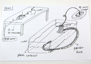
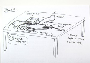
It has been fun to prepare the demos, and a lot of work too. Below are my sketches for two of the OpenSprinkler demos:
IMG_2713IMG_2714

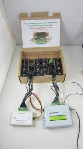
and some real gears to go with the two demos:

IMG_2715IMG_2712

In terms of promotional materials, new this year I have made a banner and some business cards to be distributed at the table:
IMG_2718IMG_2719

These were made in the last minute, so they are not as professionally looking as I wanted, but the essential information is there 🙂 Also, I will have lots of colorful info pages and pictures at the table.

Time to go to sleep and prepare for the trip tomorrow. Hope to see you at the Maker Faire OpenSprinkler booth!

A VirtualBox Image for Compiling OpenSprinkler Source Code

I know, it has been a pain to compile OpenSprinkler 1.x source code, mainly because the firmware has grown to the point that you can only compile it successfully (i.e. within 32KB size) under a particular version of avr-gcc (4.5.3) in a particular version of Linux. This is very annoying for users who want to modify the source code and experiment with new features. That’s why I have decided to create a VirtualBox image with all the necessary software and settings that you need to easily compile it, without having to install a separate Linux system yourself.

Before you continue reading, please note that the VirtualBox Image is only useful if you are trying to modify the compile the source code yourself. To upload a pre-compiled firmware, you do not need any of these.

Wait, What?
VirtualBox is a free software that you can use to install and run a virtual operating system (OS) on your existing OS. Let’s say your computer runs Windows (i.e. the host OS). With VirtualBox, you can run a virtual OS (e.g. Linux) under the host OS, as if it is a Windows application but it’s a fully functional Linux system. This makes it easy to switch between different OS without having to restart your computer. VirtualBox is quite mature now. It makes use of hardware virtualization features available on most modern CPUs to provide fast speed. So even though you are running a virtual OS, it feels just as fast as a native OS.

One of the benefits of virtual OS is that the entire OS and all settings are stored in a single file — the VirtualBox Image — on your host system. So you can easily replicate the same virtual OS on different hosts by a simple copy-paste of the image file.

Download
To make it easy to compile OpenSprinkler code, I created a VirtualBox Image for Linux Mint 13 with all the necessary software installed. You can download the virtual image file from here:

Warning: the file size is 2.1GB, so it will take some time to download. Meanwhile, you can read the instructions below.
User and Password: the virtual OS has a default sudo user opensprinkler and the password is the same as the user name.
VMWare Users: check this forum post for instructions of converting VirtualBox image to VMWare image.
Unzip in Windows: do not use the built-in zip/unzip tool of Windows because it seems unable to recognize the correct file size. Use a third-party software such as 7-Zip or WinRAR.


Instructions
Step 1. Install VirtualBox

Download and install the latest version of VirtualBox from its official website. You should install the version corresponding to your host OS (Windows, Mac etc.). In the following I will use Windows as an example. After installing the software, you also need to install the VirtualBox Extension Pack. This is platform independent.

Step 2. Add a New Virtual OS
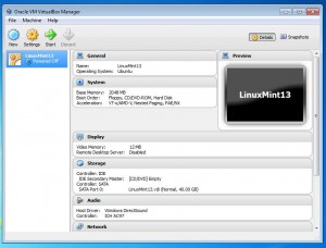
Unzip the file you downloaded to a local folder. I recommend creating a folder named VirtualBox VMs in your home directory, and unzip everything there. Next, run VirtualBox you just installed, and click on menu Machine -> Add. Navigate to the folder VirtualBox VMs \ LinuxMint13 and select the LinuxMint13.vbox file. Then click on Open to add the file. Now you should see an item named LinuxMint13 in the virtual OS list.

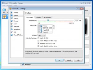
Click on Settings and make sure the default settings are compatible with your system. In particular, you should check if the Base Memory allocated to your virtual OS is not too large (it defaults to 2GB but depending on how much physical memory you have you may need to reduce it to 1GB).

virtualbox_newvirtualbox_settings

Now you can click on Start to start the virtual OS. There will be a bunch of dialog boxes popping up with various information. If this is the first time you are using VirtualBox, you should read them thoroughly. Once the virtual OS boots up, you should see the desktop as shown in the following. If you want, you can press Ctrl-F to quit full screen mode, so the virtual OS will look like a normal Windows application running alongside with other applications.

virtualbox_desktop

Step 3. Compile OpenSprinkler Code
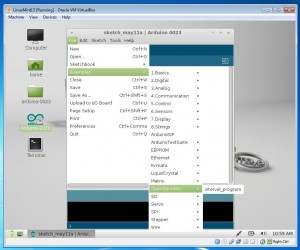
Arduino 0023 is pre-installed in the virtual OS. So you can just double click on the desktop icon to run it. Also, firmware 1.8.3 source code is pre-installed. So all you need to do to get started is to go to menu File -> Examples -> OpenSprinkler -> interval_program and then you can compile the code directly. If you need to change and file, or update to new firmware source code, everything is located in the arduino-0023/libraries/OpenSprinkler folder on the desktop.

virtualbox_arduino

Note: the following two steps are revelent:

  • Specify your hardware version by opening file arduino-0023/libraries/OpenSprinkler/defines.h, and uncomment one of the lines #define SVC_HW_VERSION that corresponds to your hardware version. To identify your hardware version, check the version number printed at the top of your OpenSprinkler circuit board. The current version is 1.4.
  • If you own OpenSprinkler v1.0 or 1.1, you can no longer upload a program through FTDI. Instead, you need an external ISP programmer. An inexpensive USBtiny programmer is available at Rayshobby Shop.

Step 4. Upload Compiled Code
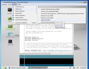
To upload the compiled code to your OpenSprinkler controller, first connect OpenSprinkler to your computer through the USB port. Then go to the VirtualBox software, and click (in the menu) Devices -> USB Devices -> USBtinySPI. This will allow the OpenSprinkler’s built-in USBtiny programmer to pass through directly to the virtual Linux and appear as a native device. Finally, click on the Upload button in Arduino and you are all set.

virtualbox_usbtiny

That’s all. Hope my effort is helpful for those who want to compile OpenSprinkler source code. Feel free to leave comments, and enjoy playing with the virtual Linux!


24VAC to 5VDC Conversion

Voltage conversion from 24VAC to 5VDC is quite useful, because a lot of home automation devices use 24VAC, including sprinkler solenoids, home surveillance systems etc. Having a conversion module makes it easy to use a single power supply, without a separate 5V adapter for your control circuit. There are plenty of resources you can find online about it. But these resources are rather scattered. So in this blog post I will summarize and discuss the common choices.


AC to DC Rectification

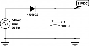
Before we begin, the first step is to have a rectifier that converts voltage from AC to DC. The common choices are half-wave rectifier (which requires just one diode) or full-wave rectifier (which requires four diodes). For simplicity, I will use half-wave rectifier as an example. The typical schematic of a half-wave rectifier is as follows:

half-wave-rectifier

It’s simply a diode followed by a capacitor to smooth out the rectified AC waves. As we know, diode only allows current to flow in one direction, so after the AC voltage passes through the diode, only positive voltage remains. The diode must be selected based on the maximum reverse voltage and the maximum current. One thing easy to forget is that when we talk about 24VAC, we mean the RMS (root-mean squared) magnitude of the voltage is 24V. Since AC voltage is a sine wave, the peak voltage is actually 24 * sqrt(2) = 34V, which is quite a bit higher. The maximum reverse voltage applied on the diode is therefore 34 – (-34) = 68V, which is when the AC voltage runs to the negative peak. So a diode with 70V peak reverse voltage is sufficient.

In practice, transformers that are rated 24VAC usually have a higher no-load voltage, which can vary between 26VAC up to 28VAC. This is typical, and the voltage is supposed to drop close to 24VAC under maximum load (i.e. the current rating of the transformer). As a result, when the circuit is powered on, the transformer can output a peak instantaneous voltage of up to 28 * sqrt(2) = 39.6V.

In the schematic above, I’ve picked a 1N4002 diode (70V reverse voltage, 1A current) and a 100uF/50V capacitor. These should work well for common scenarios. Note that the voltage output on the capacitor is approximately 34V – 1V (diode’s forward drop voltage) = 33VDC. Again, when the transformer is well below maximum load, the output voltage can go as high as 39.6V – 1V = 38.6V.

So next time if you see a power transformer rated 24VAC, after rectification, gives 39VDC, don’t be surprised!!


Now that we have a DC voltage, the next part is to step it down to 5VDC. We want it to be regulated, so that the voltage won’t fluctuate much. There are a variety of solutions:

1. Zener Diode

Probably the simplest solution is to use a Zener diode. As we know, a Zener diode can force the voltage across it to remain constant (break-down voltage) when it’s in the break-down condition. This condition is met when the current flowing through it (in reverse direction) is at least a few milli-amps (5mA typical) but less than the maximum current allowed (e.g. the diode’s power rating divided by its break-down voltage). For example, a 5V/1W Zener will remain in break-down condition when the reverse current is between 5mA and 1W/5V = 200mA. The typical schematic is shown as follows:

zener_regulator

Here resistor R1 is used for current limiting. Assume D2 is a 5V Zener diode, and the circuit on the right-hand side draws about 180mA current. R1 must be selected such that the current flowing through it is 180mA plus at least 5mA to keep D2 in break-down condition. So we have R1 = (33 – 5) / 0.185 = 150 ohm. Note that D2 should be rated at least 1W, because in case of open-circuit, it needs to absorb the entire 185mA without burning out.

Now let’s take a look at the power rating of the resistor R1. Since the current flowing through it is 185mA, the power is 0.185 A * 0.185 A * 150 ohm = 5.1 Watt. Wholly crap — this is gotta be a big resistor, isn’t it :). Well, this is the unfortunate drawback of a Zener diode based regulator, that is, it can waste a lot of power and require a bulky resistor. Fundamentally, it regulates the voltage by converting the voltage differential to heat. In this case, the voltage differential is quite big (33V vs. 5V), and the current draw is fairly large (180mA) too, so it ends up wasting a lot of power in heat.

Another drawback is that to increase the current draw, we must decrease R1. Otherwise, if the output circuit starts to draw, say 250mA, that will take D2 out of its break-down condition, and the output voltage is not regulated any more. So overall it is only suitable if the current draw is constant and small (e.g. tens of milliamps).


2. Linear Regulator

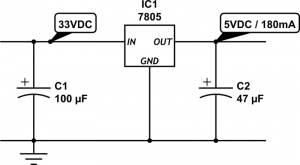
Another simple solution is to use a linear regulator, such as the popular 7805. The typical schematic is as follows:

linear_regulator

The circuit is quite simple, and the output current can vary across a wider range. However, linear regulator shares the same drawback with Zener diodes, that is, it fundamentally works by converting voltage differential to heat. As a result, it wastes the same amount of energy (5.1 Watt in this case) in heat. This is not only a matter of waste, but also it requires a large heat sink to dissipate the heat, otherwise the regulator will burn and smoke. So clearly not an efficient solution. In fact, the efficiency of a linear regulator is the ratio between the output and input voltages. In this case, it is 5 / 33 = 15.15%, which is very poor.


3. Switching Regulator

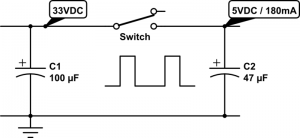
Now we have come to my favorite topic: switching regulator, also known as switching converter, or switch-mode power supply (SMPS). It uses transistors and a reactive component, namely inductor, to convert voltages much more efficiently. Ideally the switching converter works by simulating the following:

smps_ideal

That is, imagine there is an automated switch between the input and output. When the switch is turned on, it connects the input to output, and when it turns off, the input and output are disconnected. This essentially generates a square wave with 33V peak voltage, and the duty cycle is determined by the switch. Suppose the duty cycle is 15.15%, as long as the switching frequency is sufficiently high, at the output it would seem as if you have a constant voltage of 33 * 15.15% = 5V. That’s it, simple!

The main advantage of switching regulator is that since there is no resistive element, theoretically there is no energy loss at all, so the conversion efficiency is 100%! Of course in practice there will be some energy loss due to the imperfections of electronic components. Still, even at 75% efficiency, we are talking about a power waste of only (5V * 0.18A / 0.75) – (5V * 0.18A) = 0.3 Watt, much better than the 5.1 Watt waste you saw previously with a linear regulator.

The schematic above may look very simple. But it doesn’t tell the whole story. Implementing the switch is more complicated than you might think. That brings out the drawback of a switching regulator, namely cost and circuit complexity. It typically involves a transistor or MOSFET that functions as a digitally controlled switch, an oscillator circuit that generates a control square wave, a voltage reference and feedback module that monitors the output voltage, and finally a current sensing or thermal shutdown module that protects the regulator. That’s why switching regulators are typically provided as integrated circuits.

MC34063
Probably the cheapest and most widely used switching regulator is MC34063. The volume pricing (quantity 100+) is only 20 to 30 cents. Dave Jones at the EEVblog has a nice video tutorial about how to use MC34063. Also, there are a lot of MC34063 calculators you can find online, which will help you figure out the component values and parameters.

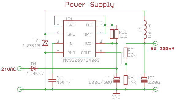
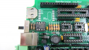
The schematic on the left below shows what I have been using for OpenSprinkler. MC34063 has a maximum input voltage of 40V (and some manufacturers make it 45V), so it’s perfect for our purpose. The main peripheral elements include inductor L1 (150uH), Schottky diode D2 (1N5819), timing capacitor CT (which controls the switching frequency), current limiting resistors Rsc (0.5 ohm), and feedback resistors RT and RB. This circuit can provide 5V 300mA output. The image on the right below shows a picture of the switching regulator section on OpenSprinkler 1.42u DIY kit.

mc34063_schIMG_2627

IMG_2666On OpenSprinkler Pi, Rsc is reduced to 0.33 ohm (three 1 ohm resistors in parallel) in order to provide higher current required by RPi. The picture on the left shows the switching regulator section on OpenSprinkler Pi, which uses all surface mount components.

MC34063 is quite flexible. It’s not only useful for step-down voltage conversion, but it can also do step-up conversion (i.e. the output voltage is higher than input voltage), and voltage inversion. On the other hand, it requires a number of peripheral components, and picking the right component values can be tricky, especially if the output current can vary across a wide range. It’s also prone to noise (remember those annoying humming noise from cheap power adapters), and its maximum current is limited to 1.5A.

Overall if you want a cheap switching regulator, and your circuit draws roughly a fixed amount of current well below 1.5A, then MC34063 is a great choice to consider.

LM2596
More recently I’ve started using LM2596 as a replacement for MC43063. I came across it when I was shopping for a modular step-down converter and noticed this one from Amazon.com. LM2596 provides up to 3A output current, requires only a small number of peripheral components, and is more reliable and less noisy. In fact, when I started working on OpenSprinkler, I have used a similar product LM2574 for a while, but that has a current limit ot 500mA, and the switching frequency is much lower.

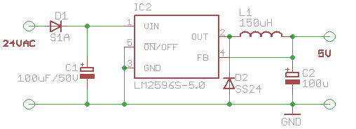
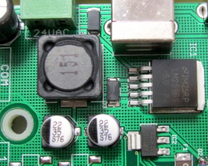
Here is the new design of the voltage conversion section in the upcoming OpenSprinkler 2.0 and OpenSprinkler Pi 1.1:

lm2596_schIMG_2709

It uses LM2596-5.0, which has a fixed output voltage of 5.0V. The number of peripheral elements is minimal, and the circuit design is very clean. The main downside is that it is considerably more expensive than MC34063. So the extra capabilities don’t come for free 🙂 Still, for reliability and clean design, I have decided to adopt it for all future circuits.


4. Other Solutions

The above has summarized the common choices I’ve learned through my experience. There are certainly other solutions as well. For example, you can use a transformer to step 24VAC down to 5VAC, then from that point on you can use a rectifier followed by a linear regulator to convert it further to 5VDC. This is fairly efficient because transformers can have high efficiency, and the linear regulator in this case is also efficient because the voltage differential is small. However, transformers are bulky and expensive. and this solution is not suitable if the input voltage varies across a wide range.

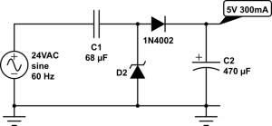
Another choice is to use a capacitor for current limiting, in conjunction with a rectifier and a 5.6V Zener diode for voltage regulation. The idea is similar to solution 1 above, except it uses the capacitor’s reactance (instead of resistor’s resistance) to limit current. Since there is little energy loss, this is very efficient and is similar to the transformerless power supply design, which is frequently found in small wall adapters. Unfortunately, to provide sufficiently high output current (more than tens of milliamps), you will a capacitor that has high capacitance (e.g. 100uF) and is non-polarized. This is not easy to find in real life.

transformerless_sch

Finally, you may be wondering why not use a resistor-based voltage divider to split 5VDC out of the 33V rectified input? Well, this is a terrible idea in almost any circumstance I can think of. The reason is that the output voltage will fluctuate considerably depending on the current draw. In other words, it is not regulated. So I can’t think of any real use of it other than providing voltage reference.

That’s all. I hope this blog post provides useful information for your own power supply design.