OpenSprinkler Interval Program is now available for OSPi

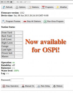
Good news to the OpenSprinkler Pi users: the same interval program firmware that runs on the latest OpenSprinkler has now been ported to OpenSprinkler Pi! This is due entirely to the generous contributions by Dan Kimberling, who ported the OpenSprinkler’s Arduino code to Python. The code is available for download at Dan’s GitHub repository. Instructions can be found at the Rayshobby Wiki page:

(Note: the grayed-out instructions below are obsolete and are only kept here for archiving purpose. Please follow the instructions on the Wiki page above for how to install and use the latest software. Thanks.)


For anyone who is unfamiliar with RPi, here are some basic instructions to follow:

  • First, ssh to your RPi (or connect your RPi to a monitor and open a Terminal), and type in run the following command in one single line(i.e. the ‘wget’ command, space, and the very long link): wget https://github.com/rayshobby/opensprinkler/raw/master/OpenSprinkler%20Pi/software/demos/interval_program/ospi.tar.gz
  • Next, run tar zvxf ospi.tar.gz. This will unzip the file to a subfolder named OSPi in your current directory.
  • Now, cd OSPi, and then run sudo python ospi.py (note that you will need to type in your RPi account password). This will start the web server.
  • Open a browser on your computer or any device that’s connected to the same network as your RPi, and type in your RPi’s IP address, followed by colon, and the default port number 8080. For example, for my RPi, the address is http://192.168.1.147:8080. You should now see the homepage of the interval program demo. Note that the port number can be changed to other values, in which case you need to check the source files to figure out how to make the change (or post a message on the forum and I am sure someone will help you).


interval_program_ospiospi_header

This demo program is the same as OpenSprinkler 1.8.2 firmware. So you can follow the OpenSprinkler Online User Manual for usage instructions. I believe all features of the firmware are supported. Keep in mind that this is still work in progress, so there are glitches and bugs that will be ironed out over time. If you are a developer, you are welcome to improve the code or help fixing bugs. The backbone of the software is based on web.py, a popular and easy-to-use web framework for Python.

Also keep in mind that if you have RPi rev. 2 (which is the current model), you need to open ospi.py and edit a port number. Details can be found in the README.txt file. P.S., it’s generally a good idea to read the README.txt first before you start doing anything.

These will be the basics to get you started. If you have any questions, feel free to post a message on the forum.

Finally, a big thank-you again to Dan Kimberling for his time and efforts in making this available to the public. This is an example of the true spirit of open-source development and community support. I am very excited to see additional user contributions to the OpenSprinkler Pi project!

Annoying ribbon cable problem with recent orders of OpenSprinkler Pi

Hi, this is an alert to users who recently ordered OpenSprinkler Pi: we’ve found an annoying problem with the 8-pin ribbon / rainbow cable that comes with the package. Apparently many of the cables have disconnected crimp wires, causing the OSPi to not respond to RPi, or even worse, causing all stations to turn on at the same time. I estimated that there are potentially up to 60 orders that might be affected. We’ve proactively taken actions to send a replacement cable to everyone who ordered OSPi recently (within the last 2 weeks). If you are seeing an issue of your OSPi not responding to RPi, try to use a multimeter to measure the connection on each of the 8 wires of the cable. If any wire is not connected, please email to [email protected] and we will send you a replacement cable right away.

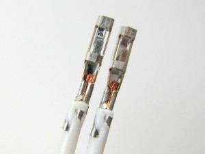
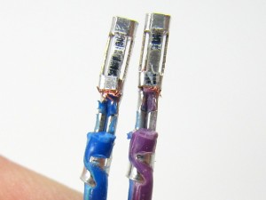
Here is a closer look at the cause of the problem. When I take the wire out of the crimp connector, you can clearly see that the good ones (shown on the left below) have metal wires tightly secured by the crimps, while the bad ones (shown on the right below) have the metal wires cut from the cable, resulting in disconnection. This is probably due to a defective wire stripper or crimp tool, or incorrect operation that causes the metal wires to be completely cut through. In any case, I’ve informed the supplier and complained about the the quality, and will never order from them again.

IMG_2963IMG_2965

So the lesson to learn here is that when testing OSPi, we really should use the individual cable that goes with each board, instead of using a common testing cable. Another lesson to learn is to never overlook any part, even something as simple as a cable!

I became aware of the cable issue when a couple of users reported that their OSPi did not work. This is very puzzling because every single board has been tested and verified, so the chance of DOA is very small. I’ve asked two of them to send their boards back to me, and after testing, I couldn’t find any obvious problem — the board works fine, and all demo programs work fine. However, until yesterday, I have apparently overlooked the problem with the cable: when testing, we have always used a common testing cable, instead of the user’s cable. Partly it’s because I never thought the cable would have any problem at all. Now I’ve learned a lesson, and it’s a good lesson to learn!

2013 Bay Area Maker Faire Summary

First off, my apology for not updating the blog for a while. Right after the Bay Area Maker Faire on May 18 and 19, I went to a trip to the UK for about ten days. Then as I came back, I was faced with a load of orders that need to be processed immediately. My friend Don and I spent three days non-stop shipping out packages. Now that all the back orders have been processed, I finally felt relieved and can come back to take care of the blog.

As a quick summary of the 2013 Maker Faire: we had a great show. A big thumb-up to Aaron Newcomb for helping me out. Without him, I would not have made it to the Maker Faire. Lots of people came by, chatted with us, provided valuable comments and suggestions, and expressed appreciation and love 🙂 I took pictures with Chris Anderson, and Eben Upton and Liz Upton. I also met and chatted with Laen from OSH Park, Ian Lesnet from Dangerous Prototypes, Mark Frauenfelder (Editor-in-Chief of the Make Magazine), Jason Babler (Creative Director of Maker Media), Michael Caster from the Maker Shed, and many others. This is such a fantastic event, and a great opportunity to meet and make connections with other makers.

20130518_12070120130519_151115

This year we didn’t bring many physical goods sell at the Maker Faire, but instead directed people to place orders online. This way we can devote more time to talk to people. Two interesting things I learned this year: First, AASaver is surprisingly popular and received much interest, but unfortunately I didn’t foresee this and hence did not prepare any new stock. What a pity! If I end up going to the New York Maker Faire later this year, I will make sure to take a batch of AASavers there. Second, kids really enjoy playing with flashing LEDs. We’ve set out a table with coin batteries and self-flashing LEDs, and provided simple instructions to make an LED throwie so people can make one right at the booth and take it away as a gift. This was hugely popular, and all the LEDs and batteries were consumed in no time. Apparently I should prepare more of these next time!

Of course the primary focus of the audience at our booth is on OpenSprinkler and OpenSprinkler Pi (OSPi). Since the release of OSPi just a couple of months ago, it has started gaining significant interest and has become the fastest growing product on my site. So far there have been more than 350 OpenSprinkler Pis out there in the wild. And as you can see from the forum, lots of people have been keenly working on developing their own software, using different programming languages and implementing advanced features such as weather-based control and sensor-based control. As I will talk about in the next post, the same firmware that’s running on the microcontroller-based OpenSprinkler has now been ported to OSPi, thanks to the generous contribution by Kimberling. So now you can run the same full-featured interval program on OSPi as in the standard OpenSprinkler.

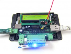
But if you think the microcontroller-based OpenSprinkler is losing its charm, you couldn’t be more wrong 🙂 Although not growing as fast as OSPi, it’s still selling extremely well. Anyone who recently ordered the assembled OpenSprinkler has probably found out that we’ve been `secretly’ upgrading your order to a pre-release version of OpenSprinkler 2.0. As I will talk about in a follow-up post, OpenSprinkler 2.0 has an upgraded mcu (ATmega644), microSD card slot, the ability of adjusting LCD backlight brightness and contrast, more available pins to interface with external sensors and actuators, and pin headers to directly plug in an RF transmitter in order to interface with remote devices. The only difference of the pre-release version with the final version of 2.0 is in the enclosure design: the pre-release uses the current enclosure, and the final version (which is in production at SeeedStudio) will be using the new injection molded enclosure. There are many good reasons to prefer the microcontroller-based OpenSprinkler over OSPi: it is pre-flashed and works out of the box, so no hassle with installing raspbian, doing ssh, or dealing with Linux; it has LCD, buttons, and a number of analog pins to interface with external sensors; also I personally really like microcontrollers because of their simplicity and the fact that the controller is instant on when you need to restart it.

Uhh, I think my thoughts are already drifting away from the Maker Fairem which is supposed to be the focus of this post. So let me conclude this post here, and more exciting posts about recent updates will follow next!

Preparing for Bay Area Maker Faire 2013

Contrary to what I mentioned in a previous post, I have made the very last-minute decision to attend the Bay Area Maker Faire 2013. I will be flying out of Massachusetts early tomorrow morning, and get to the Maker Faire ground in the afternoon to do initial setup. Aaron Newcomb has kindly volunteered to help me at the booth. If you are planning to come to the Maker Faire, be sure to drop by our booth (exhibit 3375, Expo Hall with commercial makers), and watch our demos.

We will be showing most products I’ve developed so far: OpenSprinkler (including DIY 1.42u, the new assembled OpenSprinkler 2.0, and new injection molded enclosure), OpenSprinkler Pi, SquareWear (with lots of pictures of wearable electronics workshops I’ve hosted int he past, and SquareWear demos), AASaver (including the upcoming AASaver 2.0 I just blogged about earlier tonight). So it will be quite a show!

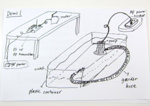
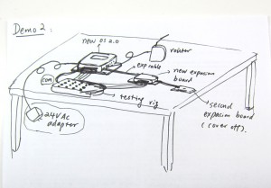
It has been fun to prepare the demos, and a lot of work too. Below are my sketches for two of the OpenSprinkler demos:
IMG_2713IMG_2714

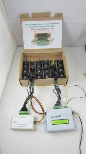
and some real gears to go with the two demos:

IMG_2715IMG_2712

In terms of promotional materials, new this year I have made a banner and some business cards to be distributed at the table:
IMG_2718IMG_2719

These were made in the last minute, so they are not as professionally looking as I wanted, but the essential information is there 🙂 Also, I will have lots of colorful info pages and pictures at the table.

Time to go to sleep and prepare for the trip tomorrow. Hope to see you at the Maker Faire OpenSprinkler booth!

New Development PCB in the Mail Today

Yup, I opened my mail box and found the lovely purple envelope from OSHPark. What’s in it?
IMG_2720IMG_2721

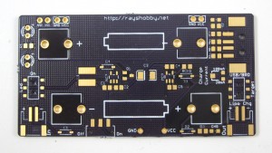
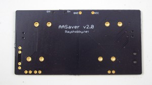
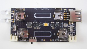
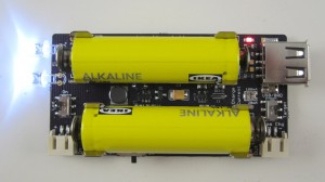
Ah ha, it’s the new AASaver 2.0 prototype PCB. I can’t help getting my hands on it, so I quickly assembled two. Here is what the assembled board looks like (without and with AA batteries):

IMG_2722IMG_2723

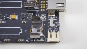
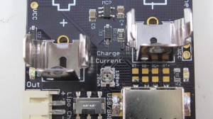
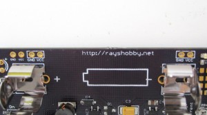
AASaver 2.0 is sort of a ‘mega’ version of AASaver 1.0: like 1.0, it takes two AA batteries and serves dual functions as both an LED flashlight and breadboard power supply. But it can do much more. First of all, I’ve added a LiPo charger circuitry so that you can use two AA batteries to charge an external LiPo battery:
IMG_2728IMG_2726

I’ve also added an SMT potentiometer (trimmer) to adjust the charge current (see the picture on the right above), anywhere from 20mA to 100mA. This is not a random addition — there is a good reason to have this feature, which you shall see in a minute.

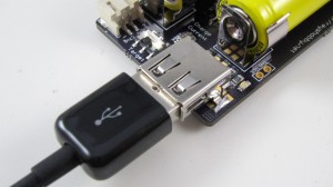
Another BIG addition is the functionality to charge USB devices like cell phones. Yup, you heard it right: there is a built-in type A USB receptacle that allows you to plug in a USB charging cable to add juice to your phone, MP3 player etc.

IMG_2725

So this is similar to Adafruit’s MintyBoost, except that there is a catch: on MintyBoost, you use a pair of fresh battery to charge the phone, but with AASaver the whole point is to harvest the remaining energy in used or old batteries. How does this affect anything? Well, used batteries typically cannot supply a high amount of current, so you can’t use them directly to charge the phone — it simply won’t provide enough current to charge. The trick is to dump the energy slowly into a LiPo battery, then charge the phone through the LiPo battery later! Essentially the LiPo battery serves as a ‘water bucket’, which accumulates charges slowly (like water drops), so that even used AA batteries can charge it; once the ‘water bucket’ has accumulated enough charges, it can dump the ‘water’ at much faster rate. This is the same idea as how solar chargers work: solar cells are too weak to charge phones directly, but you can build up the charges by leveraging a battery. Now you see why there is a built-in LiPo charger!

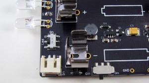
The picture below shows where the LiPo battery should be plugged in when you want to use it to charge USB devices. In sum, if you have a fresh pair of AA batteries, you can charge USB devices directly; otherwise you first charge the LiPo battery with a controllable charging current (20mA recommended), then use the LiPo to charge USB devices. The circuit of AASaver 2.0 accepts either AA or LiPo as the source of its boost converter, and directs the boosted 5V to either USB port, or LiPo charger, selectable through the ‘Target’ switch at the right-end of the board. On top of these, there is a separate switch for turning on the flashlight LEDs, and there are pin headers spaced appropriately to match a standard breadboard, so you can use it as a battery-based breadboard 5V power supply. As you can see, it has a load of new features to provide better and more flexible ways to save your AA batteries 🙂

IMG_2727IMG_2728

IMG_2727IMG_2724

A VirtualBox Image for Compiling OpenSprinkler Source Code

I know, it has been a pain to compile OpenSprinkler 1.x source code, mainly because the firmware has grown to the point that you can only compile it successfully (i.e. within 32KB size) under a particular version of avr-gcc (4.5.3) in a particular version of Linux. This is very annoying for users who want to modify the source code and experiment with new features. That’s why I have decided to create a VirtualBox image with all the necessary software and settings that you need to easily compile it, without having to install a separate Linux system yourself.

Before you continue reading, please note that the VirtualBox Image is only useful if you are trying to modify the compile the source code yourself. To upload a pre-compiled firmware, you do not need any of these.

Wait, What?
VirtualBox is a free software that you can use to install and run a virtual operating system (OS) on your existing OS. Let’s say your computer runs Windows (i.e. the host OS). With VirtualBox, you can run a virtual OS (e.g. Linux) under the host OS, as if it is a Windows application but it’s a fully functional Linux system. This makes it easy to switch between different OS without having to restart your computer. VirtualBox is quite mature now. It makes use of hardware virtualization features available on most modern CPUs to provide fast speed. So even though you are running a virtual OS, it feels just as fast as a native OS.

One of the benefits of virtual OS is that the entire OS and all settings are stored in a single file — the VirtualBox Image — on your host system. So you can easily replicate the same virtual OS on different hosts by a simple copy-paste of the image file.

Download
To make it easy to compile OpenSprinkler code, I created a VirtualBox Image for Linux Mint 13 with all the necessary software installed. You can download the virtual image file from here:

Warning: the file size is 2.1GB, so it will take some time to download. Meanwhile, you can read the instructions below.
User and Password: the virtual OS has a default sudo user opensprinkler and the password is the same as the user name.
VMWare Users: check this forum post for instructions of converting VirtualBox image to VMWare image.
Unzip in Windows: do not use the built-in zip/unzip tool of Windows because it seems unable to recognize the correct file size. Use a third-party software such as 7-Zip or WinRAR.


Instructions
Step 1. Install VirtualBox

Download and install the latest version of VirtualBox from its official website. You should install the version corresponding to your host OS (Windows, Mac etc.). In the following I will use Windows as an example. After installing the software, you also need to install the VirtualBox Extension Pack. This is platform independent.

Step 2. Add a New Virtual OS
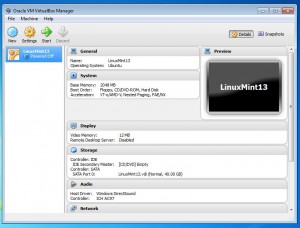
Unzip the file you downloaded to a local folder. I recommend creating a folder named VirtualBox VMs in your home directory, and unzip everything there. Next, run VirtualBox you just installed, and click on menu Machine -> Add. Navigate to the folder VirtualBox VMs \ LinuxMint13 and select the LinuxMint13.vbox file. Then click on Open to add the file. Now you should see an item named LinuxMint13 in the virtual OS list.

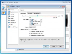
Click on Settings and make sure the default settings are compatible with your system. In particular, you should check if the Base Memory allocated to your virtual OS is not too large (it defaults to 2GB but depending on how much physical memory you have you may need to reduce it to 1GB).

virtualbox_newvirtualbox_settings

Now you can click on Start to start the virtual OS. There will be a bunch of dialog boxes popping up with various information. If this is the first time you are using VirtualBox, you should read them thoroughly. Once the virtual OS boots up, you should see the desktop as shown in the following. If you want, you can press Ctrl-F to quit full screen mode, so the virtual OS will look like a normal Windows application running alongside with other applications.

virtualbox_desktop

Step 3. Compile OpenSprinkler Code
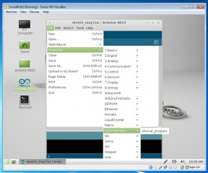
Arduino 0023 is pre-installed in the virtual OS. So you can just double click on the desktop icon to run it. Also, firmware 1.8.3 source code is pre-installed. So all you need to do to get started is to go to menu File -> Examples -> OpenSprinkler -> interval_program and then you can compile the code directly. If you need to change and file, or update to new firmware source code, everything is located in the arduino-0023/libraries/OpenSprinkler folder on the desktop.

virtualbox_arduino

Note: the following two steps are revelent:

  • Specify your hardware version by opening file arduino-0023/libraries/OpenSprinkler/defines.h, and uncomment one of the lines #define SVC_HW_VERSION that corresponds to your hardware version. To identify your hardware version, check the version number printed at the top of your OpenSprinkler circuit board. The current version is 1.4.
  • If you own OpenSprinkler v1.0 or 1.1, you can no longer upload a program through FTDI. Instead, you need an external ISP programmer. An inexpensive USBtiny programmer is available at Rayshobby Shop.

Step 4. Upload Compiled Code
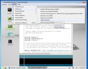
To upload the compiled code to your OpenSprinkler controller, first connect OpenSprinkler to your computer through the USB port. Then go to the VirtualBox software, and click (in the menu) Devices -> USB Devices -> USBtinySPI. This will allow the OpenSprinkler’s built-in USBtiny programmer to pass through directly to the virtual Linux and appear as a native device. Finally, click on the Upload button in Arduino and you are all set.

virtualbox_usbtiny

That’s all. Hope my effort is helpful for those who want to compile OpenSprinkler source code. Feel free to leave comments, and enjoy playing with the virtual Linux!


24VAC to 5VDC Conversion

Voltage conversion from 24VAC to 5VDC is quite useful, because a lot of home automation devices use 24VAC, including sprinkler solenoids, home surveillance systems etc. Having a conversion module makes it easy to use a single power supply, without a separate 5V adapter for your control circuit. There are plenty of resources you can find online about it. But these resources are rather scattered. So in this blog post I will summarize and discuss the common choices.


AC to DC Rectification

Before we begin, the first step is to have a rectifier that converts voltage from AC to DC. The common choices are half-wave rectifier (which requires just one diode) or full-wave rectifier (which requires four diodes). For simplicity, I will use half-wave rectifier as an example. The typical schematic of a half-wave rectifier is as follows:
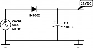
half-wave-rectifier

It’s simply a diode followed by a capacitor to smooth out the rectified AC waves. As we know, diode only allows current to flow in one direction, so after the AC voltage passes through the diode, only positive voltage remains. The diode must be selected based on the maximum reverse voltage and the maximum current. One thing easy to forget is that when we talk about 24VAC, we mean the RMS (root-mean squared) magnitude of the voltage is 24V. Since AC voltage is a sine wave, the peak voltage is actually 24 * sqrt(2) = 34V, which is quite a bit higher. The maximum reverse voltage applied on the diode is therefore 34 – (-34) = 68V, which is when the AC voltage runs to the negative peak. So a diode with 70V peak reverse voltage is sufficient.

In practice, transformers that are rated 24VAC usually have a higher no-load voltage, which can vary between 26VAC up to 28VAC. This is typical, and the voltage is supposed to drop close to 24VAC under maximum load (i.e. the current rating of the transformer). As a result, when the circuit is powered on, the transformer can output a peak instantaneous voltage of up to 28 * sqrt(2) = 39.6V.

In the schematic above, I’ve picked a 1N4002 diode (70V reverse voltage, 1A current) and a 100uF/50V capacitor. These should work well for common scenarios. Note that the voltage output on the capacitor is approximately 34V – 1V (diode’s forward drop voltage) = 33VDC. Again, when the transformer is well below maximum load, the output voltage can go as high as 39.6V – 1V = 38.6V.

So next time if you see a power transformer rated 24VAC, after rectification, gives 39VDC, don’t be surprised!!


Now that we have a DC voltage, the next part is to step it down to 5VDC. We want it to be regulated, so that the voltage won’t fluctuate much. There are a variety of solutions:

1. Zener Diode

Probably the simplest solution is to use a Zener diode. As we know, a Zener diode can force the voltage across it to remain constant (break-down voltage) when it’s in the break-down condition. This condition is met when the current flowing through it (in reverse direction) is at least a few milli-amps (5mA typical) but less than the maximum current allowed (e.g. the diode’s power rating divided by its break-down voltage). For example, a 5V/1W Zener will remain in break-down condition when the reverse current is between 5mA and 1W/5V = 200mA. The typical schematic is shown as follows:

zener_regulator

Here resistor R1 is used for current limiting. Assume D2 is a 5V Zener diode, and the circuit on the right-hand side draws about 180mA current. R1 must be selected such that the current flowing through it is 180mA plus at least 5mA to keep D2 in break-down condition. So we have R1 = (33 – 5) / 0.185 = 150 ohm. Note that D2 should be rated at least 1W, because in case of open-circuit, it needs to absorb the entire 185mA without burning out.

Now let’s take a look at the power rating of the resistor R1. Since the current flowing through it is 185mA, the power is 0.185 A * 0.185 A * 150 ohm = 5.1 Watt. Wholly crap — this is gotta be a big resistor, isn’t it :). Well, this is the unfortunate drawback of a Zener diode based regulator, that is, it can waste a lot of power and require a bulky resistor. Fundamentally, it regulates the voltage by converting the voltage differential to heat. In this case, the voltage differential is quite big (33V vs. 5V), and the current draw is fairly large (180mA) too, so it ends up wasting a lot of power in heat.

Another drawback is that to increase the current draw, we must decrease R1. Otherwise, if the output circuit starts to draw, say 250mA, that will take D2 out of its break-down condition, and the output voltage is not regulated any more. So overall it is only suitable if the current draw is constant and small (e.g. tens of milliamps).


2. Linear Regulator

Another simple solution is to use a linear regulator, such as the popular 7805. The typical schematic is as follows:
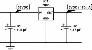
linear_regulator

The circuit is quite simple, and the output current can vary across a wider range. However, linear regulator shares the same drawback with Zener diodes, that is, it fundamentally works by converting voltage differential to heat. As a result, it wastes the same amount of energy (5.1 Watt in this case) in heat. This is not only a matter of waste, but also it requires a large heat sink to dissipate the heat, otherwise the regulator will burn and smoke. So clearly not an efficient solution. In fact, the efficiency of a linear regulator is the ratio between the output and input voltages. In this case, it is 5 / 33 = 15.15%, which is very poor.


3. Switching Regulator

Now we have come to my favorite topic: switching regulator, also known as switching converter, or switch-mode power supply (SMPS). It uses transistors and a reactive component, namely inductor, to convert voltages much more efficiently. Ideally the switching converter works by simulating the following:
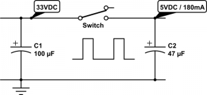
smps_ideal

That is, imagine there is an automated switch between the input and output. When the switch is turned on, it connects the input to output, and when it turns off, the input and output are disconnected. This essentially generates a square wave with 33V peak voltage, and the duty cycle is determined by the switch. Suppose the duty cycle is 15.15%, as long as the switching frequency is sufficiently high, at the output it would seem as if you have a constant voltage of 33 * 15.15% = 5V. That’s it, simple!

The main advantage of switching regulator is that since there is no resistive element, theoretically there is no energy loss at all, so the conversion efficiency is 100%! Of course in practice there will be some energy loss due to the imperfections of electronic components. Still, even at 75% efficiency, we are talking about a power waste of only (5V * 0.18A / 0.75) – (5V * 0.18A) = 0.3 Watt, much better than the 5.1 Watt waste you saw previously with a linear regulator.

The schematic above may look very simple. But it doesn’t tell the whole story. Implementing the switch is more complicated than you might think. That brings out the drawback of a switching regulator, namely cost and circuit complexity. It typically involves a transistor or MOSFET that functions as a digitally controlled switch, an oscillator circuit that generates a control square wave, a voltage reference and feedback module that monitors the output voltage, and finally a current sensing or thermal shutdown module that protects the regulator. That’s why switching regulators are typically provided as integrated circuits.

MC34063
Probably the cheapest and most widely used switching regulator is MC34063. The volume pricing (quantity 100+) is only 20 to 30 cents. Dave Jones at the EEVblog has a nice video tutorial about how to use MC34063. Also, there are a lot of MC34063 calculators you can find online, which will help you figure out the component values and parameters.

The schematic on the left below shows what I have been using for OpenSprinkler. MC34063 has a maximum input voltage of 40V (and some manufacturers make it 45V), so it’s perfect for our purpose. The main peripheral elements include inductor L1 (150uH), Schottky diode D2 (1N5819), timing capacitor CT (which controls the switching frequency), current limiting resistors Rsc (0.5 ohm), and feedback resistors RT and RB. This circuit can provide 5V 300mA output. The image on the right below shows a picture of the switching regulator section on OpenSprinkler 1.42u DIY kit.
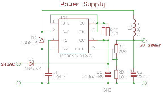
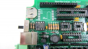
mc34063_schIMG_2627

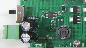
IMG_2666On OpenSprinkler Pi, Rsc is reduced to 0.33 ohm (three 1 ohm resistors in parallel) in order to provide higher current required by RPi. The picture on the left shows the switching regulator section on OpenSprinkler Pi, which uses all surface mount components.

MC34063 is quite flexible. It’s not only useful for step-down voltage conversion, but it can also do step-up conversion (i.e. the output voltage is higher than input voltage), and voltage inversion. On the other hand, it requires a number of peripheral components, and picking the right component values can be tricky, especially if the output current can vary across a wide range. It’s also prone to noise (remember those annoying humming noise from cheap power adapters), and its maximum current is limited to 1.5A.

Overall if you want a cheap switching regulator, and your circuit draws roughly a fixed amount of current well below 1.5A, then MC34063 is a great choice to consider.

LM2596
More recently I’ve started using LM2596 as a replacement for MC43063. I came across it when I was shopping for a modular step-down converter and noticed this one from Amazon.com. LM2596 provides up to 3A output current, requires only a small number of peripheral components, and is more reliable and less noisy. In fact, when I started working on OpenSprinkler, I have used a similar product LM2574 for a while, but that has a current limit ot 500mA, and the switching frequency is much lower.

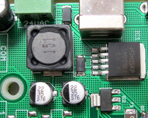
Here is the new design of the voltage conversion section in the upcoming OpenSprinkler 2.0 and OpenSprinkler Pi 1.1:
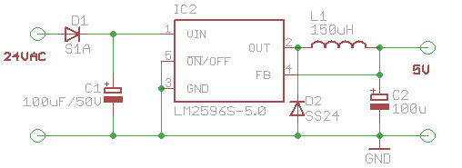
lm2596_schIMG_2709

It uses LM2596-5.0, which has a fixed output voltage of 5.0V. The number of peripheral elements is minimal, and the circuit design is very clean. The main downside is that it is considerably more expensive than MC34063. So the extra capabilities don’t come for free 🙂 Still, for reliability and clean design, I have decided to adopt it for all future circuits.


4. Other Solutions

The above has summarized the common choices I’ve learned through my experience. There are certainly other solutions as well. For example, you can use a transformer to step 24VAC down to 5VAC, then from that point on you can use a rectifier followed by a linear regulator to convert it further to 5VDC. This is fairly efficient because transformers can have high efficiency, and the linear regulator in this case is also efficient because the voltage differential is small. However, transformers are bulky and expensive. and this solution is not suitable if the input voltage varies across a wide range.

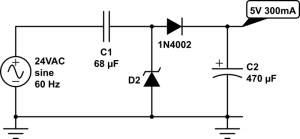
Another choice is to use a capacitor for current limiting, in conjunction with a rectifier and a 5.6V Zener diode for voltage regulation. The idea is similar to solution 1 above, except it uses the capacitor’s reactance (instead of resistor’s resistance) to limit current. Since there is little energy loss, this is very efficient and is similar to the transformerless power supply design, which is frequently found in small wall adapters. Unfortunately, to provide sufficiently high output current (more than tens of milliamps), you will a capacitor that has high capacitance (e.g. 100uF) and is non-polarized. This is not easy to find in real life.
transformerless_sch

Finally, you may be wondering why not use a resistor-based voltage divider to split 5VDC out of the 33V rectified input? Well, this is a terrible idea in almost any circumstance I can think of. The reason is that the output voltage will fluctuate considerably depending on the current draw. In other words, it is not regulated. So I can’t think of any real use of it other than providing voltage reference.

That’s all. I hope this blog post provides useful information for your own power supply design.


Maker Faire 2013 OpenSprinkler Booth Call for Help

Hi All, OpenSprinkler will have a booth at the Bay Area Maker Faire again this year. Due to a number of reasons, I cannot make it myself, but Aaron Newcomb from California has generously volunteered to host the booth for me. He will be showing demonstrations with the OpenSprinkler controller. There will also be flyers and promotional materials distributed there.

In order to make this a success, we would like to have a few more people to help. If you are going or planning to go to the Maker Faire and can help at the booth even for just a couple of hours, that would be great and much appreciated. I am happy to send free gifts to you. Anyone who can help at the booth for at least 4 hours either Saturday or Sunday will additionally get a free Maker entry pass. This is covered by the exhibit.

If you are interested in helping, please respond to this forum post by Aaron, or email me. Thanks!


Bay Area Maker Faire Web Badge

Noise Coupling Issue with DS1307 RTC

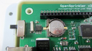
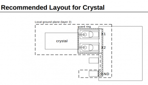
Recently a random crashing issue has surfaced on the forum regarding some of the OpenSprinkler 2.0 development boards that we sent out a few weeks ago. The background is that we have started shipping a development version of 2.0 for any recent order of the assembled OpenSprinkler. The symptom is that some of the units started crashing and losing network connection, and this seems to be always correlated with the timing running crazy off the charts. Initially I thought this issue may have been caused by a bad RTC crystal, which leads to incorrect timing, and which in turn causes the controller to get stuck. Then at some point I realized all the problematic cases happened on a particular PCB version dated Nov 2012. This helped me narrow down the search range. After a thorough comparison to the more recent version, I discovered that the problem is actually caused by a noise coupling issue with DS1307 RTC. Specifically, according to the datasheet (right image below), the region around traces between the 32.768kHz crystal and DS1307 should be shielded by a ground trace. If this is not implemented, the crystal may pick up noise from nearby traces and cause the clock to run significantly off the charts. When I designed OpenSprinkler PCBs, I had not paid attention to this recommended layout at all. Jeese, why did’t I read the datasheet carefully!

IMG_2704ds1307_recommended_layout

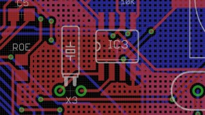
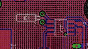
After discovering the issue, I panicked a little bit. Since I didn’t know about the issue previously, and there are hundreds of boards in production at SeeedStudios, am I screwed? It turns out that the situation is not as bad as I thought. First of all, I usually add a ground plane to fill the empty spaces between traces. As a result, on most PCB versions, there is indeed a ground plane around the traces from the crystal to the RTC. Below are examples of the traces on OpenSprinkler 1.4s, the more recent version 2.0, and the version in production at SeeedStudios:

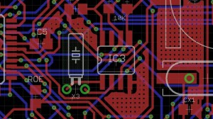
pcbtrace20pcbtrace14

pcbtrace20_new

Although they don’t match the recommended layout exactly, they are pretty good at shielding the crystal pins from picking up noise. You know, I have always questioned about those ground planes and wondered whether it’s worth my effort of adding them. Well, in this case it did save me from potentially deep trouble.

Now, in comparison, on the Nov 2012 version of 2.0, the ground plane is missing around that region (probably because there is not enough space between the traces to allow a ground plane). As a result, here is the PCB image:

pcbtrace20_alpha

Not only it is missing the ground plane in that region, but also there are all kinds of signal traces nearby, which makes is extra easy to pick up noise. This is bad, bad, bad. Now, that being said, even with the careless design, it’s not like you are guaranteed to have the problem. It more of a reliability thing: it increase the chance of noise coupling, but in many cases the issue probably doesn’t show up. In fact I was trying to reproduce the problem today on a particular PCB version that has no ground plane. After testing 8 of these, one showed a problem of extremely fast clock (5x faster than normal). And it turned out that I forgot to cut the crystal leads, which make them act like antenna to happily pick up noise. After cutting the leads, the clock went back to normal speed. This probably explains why the problem didn’t surface earlier even though I have never paid attention to the PCB trace around RTC previously.

The DIY version 1.42u is also missing the ground traces around that region. So I won’t be surprised if users have encountered a clock speed problem (although so far I have not received any report of it). In case this happens, an easy thing to try is to re-solder the 32.768kHz crystal and try to push it down to the PCB holes as much as you can. This will help reduce the length of the crystal pins and in turn reduce the chance of picking up noise. Another possibility is to simply solder the crystal directly onto the IC pins,

So overall this is a very valuable learning experience for me. I am grateful to those who reported the issue on the forum, and helped me figure out the problem as quickly as I can. There are about 10 of those Nov 2012 assembled boards out there, and I am happy to replace them for free. With that, it’s now time for me to revisit the datasheets. Never overlook them again!

The Cost of Development

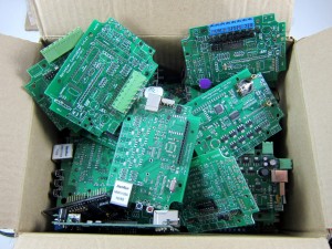
During the process of cleaning up my workshop today, I collected all the OpenSprinkler prototype boards that have had design mistakes or were built and failed in the past, and looks at this whole box of lovely PCBs:

IMG_2671

Probably no less than 30 boards in the box. It’s quite shocking to realize how many there are. By far getting prototype PCBs has been the most time-consuming and costly part of the development process. First of all, each round of prototype PCBs costs about $50 and takes 9 to 12 days of lead time (using the fastest shipping option), from places like SeeedStudio or Smart-Prototyping. The cost is not dramatic, but the lead time is quite significant unless if I am willing to pay hundreds of dollars to order from US-based services. Also, these boards are unfortunately complex enough that home DIY PCBs are no longer a viable solution.

Then, no matter how careful I am in designing the PCB, there are always a couple of unforeseen issues that had to be discovered when I actually start assembling. For example, a component might be too far away from the enclosure cutout, a component footprint might be wrong, two components might be too close to each other, the pin headers were placed in the wrong orientation, and sometimes I forget to add a ground plane. Because these issues are only discovered after one round of PCBs have arrived (then I will fix the issues, refine the design, and order another round), they make the development process sequential and cause the overall time and cost to quickly add up. The good thing is that over time I learn from lessons and accumulate tips to help me maximally avoid potential mistakes. Still, it’s inevitable to produce design issues, which can only be fixed by putting in more money and time.

When I get the finalized PCB, however, I often feel proud, as if it’s a work of art which has been refined and polished and is ready to be seen by the public. Then I get a sense of achievement. That’s the joy of working on electronic circuits 🙂